在本文中,我们将介绍如何构建带有VGA输出的低分辨率热成像。该解决方案基于Melexis MLX90640红外阵列、FPGA S7 50开发板(AMD-Xilinx Spartan-7 FPGA,带VGA输出)。

Sparkfun Melexis MLX90640 红外阵列
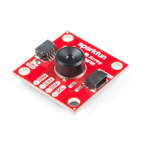
MLX90640 SparkFun IR Array Breakout 配备 32x24 热电堆传感器阵列,本质上形成低分辨率热成像相机。
MLX90640 包含 768 个 FIR 像素。集成了一个环境传感器,用于测量芯片的环境温度,以及一个电源传感器,用于测量 VDD。所有传感器(IR、Ta 和 VDD)的输出均存储在内部 RAM 中,可通过 I²C 接口访问。
该模块具有 110°x75° 视场角,温度测量范围为 -40°C-300°C。
MLX90640 SparkFun 模块已将上拉电阻连接到 I2C 总线,因此我们不推荐在开发板上使用 I2C 上拉电阻。
开发板原理图:A rty_s7_sch-rev_b.pdf
https://digilent.com/reference/_media/reference/programmable-logic/arty-s7/arty_s7_sch-rev_b.pdf

MLX90640 需要主机平台进行复杂的计算。我们的系统需要 20,000 字节或更多的 RAM。
MLX90640 的 I2C 地址为 0x33,由硬件定义。我们将使用专用的 I2C 通道来驱动 MLX90640。
MLX90640-数据表-Melexis.pdf
https://www.melexis.com/en/product/MLX90640/Far-Infrared-Thermal-Sensor-Array
VGA热成像摄像机系统设计
该系统非常简单。只需拨动开关即可开启或关闭摄像头。Microblaze 软微控制器通过 I2C 协议连接到热阵列,计算温度数据,将其转换为颜色并将其存储在 DDR3 SDRAM 内存中的非活动缓冲区中。数据存储完成后,它会将缓冲区切换至 VGA 显示。摄像头开启时,所有操作均按此进行。

FPGA硬件设计
该系统将显示来自 DDR 中的帧缓冲区的图像,使用 FPGA 逻辑中的多个组件来生成 VGA 颜色和同步信号。
BD设计

VGA层次结构块设计
VGA 层次结构基于Zybo VGA 输出 - 实时系统 - York Wiki 服务, 适用于 Microblaze

MLX90640 红外阵列驱动器
与传感器的通信是通过 I2C 协议完成的。
该设备使用 I2C 协议,支持 FM+ 模式(高达 1MHz 时钟频率),并且在总线上只能作为一个从机。

开始/停止条件
每个通信会话都由一个 START 条件启动,以一个 STOP 条件结束。START 条件由 SDA 信号由高电平跳变至低电平触发,而 STOP 条件由低电平跳变至高电平触发。两种跳变都必须在 SCL 信号为高电平时进行。
测试源代码:
go
/**
 * Example of reeding temp data from mlx90640 with the Digilent Arty S7, with animation
 */


#include "platform.h"
#include "xil_printf.h"
#include "mlx90640_api.h"

#include "xiic.h"
#include "xintc.h"
#include "xil_exception.h"
#include "sleep.h"
/*
 * The following constants map to the XPAR parameters created in the
 * xparameters.h file. They are defined here such that a user can easily
 * change all the needed parameters in one place.
 */
#define IIC_DEVICE_ID  XPAR_IIC_0_DEVICE_ID
#define INTC_DEVICE_ID  XPAR_INTC_0_DEVICE_ID
#define IIC_INTR_ID XPAR_INTC_0_IIC_0_VEC_ID

XIic IicInstance; /* The instance of the IIC device */

XIntc InterruptController; /* The instance of the Interrupt controller */

#define IIC_SLAVE_ADDR  0x33
#define IIC_SCLK_RATE  100000

volatile u8 TransmitComplete;
volatile u8 ReceiveComplete;

/*
 * The following structure contains fields that are used with the callbacks
 * (handlers) of the IIC driver. The driver asynchronously calls handlers
 * when abnormal events occur or when data has been sent or received. This
 * structure must be volatile to work when the code is optimized.
 */
volatile struct {
 int EventStatus;
 int RemainingRecvBytes;
 int EventStatusUpdated;
 int RecvBytesUpdated;
} HandlerInfo;

#define BL 55
#define DC 54
#define WIDTH 32
#define HEIGHT 24

#define TEST_BUFFER_SIZE 512
#define TA_SHIFT 8

/************************** Function Prototypes ******************************/

int IicRepeatedStartExample();

static int SetupInterruptSystem(XIic *IicInstPtr);
static void ReceiveHandler(XIic *InstancePtr);
static void SendHandler(XIic *InstancePtr);

static void StatusHandler(XIic *InstancePtr, int Event);

void VGA_Fill_Color(uint16_t color);
int MLX90640_I2CRead(uint8_t slaveAddr, uint16_t startAddress,
  uint16_t nMemAddressRead, uint16_t *data);
int MLX90640_I2CWrite(uint8_t slaveAddr, uint16_t writeAddress, uint16_t data);
void VGA_Fill_Display(float *mlx90640Frame);
void VGA_DrawPixel(uint16_t x, uint16_t y, uint16_t color);
long map(long x, long in_min, long in_max, long out_min, long out_max);

u8 SendBuffer[TEST_BUFFER_SIZE];    //I2C TX
u8 RecvBuffer[TEST_BUFFER_SIZE];    //I2C RX

u16 frame[WIDTH][HEIGHT];

const uint16_t camColors[] = { 0x480F, 0x400F, 0x400F, 0x400F, 0x4010, 0x3810,
  0x3810, 0x3810, 0x3810, 0x3010, 0x3010, 0x3010, 0x2810, 0x2810, 0x2810,
  0x2810, 0x2010, 0x2010, 0x2010, 0x1810, 0x1810, 0x1811, 0x1811, 0x1011,
  0x1011, 0x1011, 0x0811, 0x0811, 0x0811, 0x0011, 0x0011, 0x0011, 0x0011,
  0x0011, 0x0031, 0x0031, 0x0051, 0x0072, 0x0072, 0x0092, 0x00B2, 0x00B2,
  0x00D2, 0x00F2, 0x00F2, 0x0112, 0x0132, 0x0152, 0x0152, 0x0172, 0x0192,
  0x0192, 0x01B2, 0x01D2, 0x01F3, 0x01F3, 0x0213, 0x0233, 0x0253, 0x0253,
  0x0273, 0x0293, 0x02B3, 0x02D3, 0x02D3, 0x02F3, 0x0313, 0x0333, 0x0333,
  0x0353, 0x0373, 0x0394, 0x03B4, 0x03D4, 0x03D4, 0x03F4, 0x0414, 0x0434,
  0x0454, 0x0474, 0x0474, 0x0494, 0x04B4, 0x04D4, 0x04F4, 0x0514, 0x0534,
  0x0534, 0x0554, 0x0554, 0x0574, 0x0574, 0x0573, 0x0573, 0x0573, 0x0572,
  0x0572, 0x0572, 0x0571, 0x0591, 0x0591, 0x0590, 0x0590, 0x058F, 0x058F,
  0x058F, 0x058E, 0x05AE, 0x05AE, 0x05AD, 0x05AD, 0x05AD, 0x05AC, 0x05AC,
  0x05AB, 0x05CB, 0x05CB, 0x05CA, 0x05CA, 0x05CA, 0x05C9, 0x05C9, 0x05C8,
  0x05E8, 0x05E8, 0x05E7, 0x05E7, 0x05E6, 0x05E6, 0x05E6, 0x05E5, 0x05E5,
  0x0604, 0x0604, 0x0604, 0x0603, 0x0603, 0x0602, 0x0602, 0x0601, 0x0621,
  0x0621, 0x0620, 0x0620, 0x0620, 0x0620, 0x0E20, 0x0E20, 0x0E40, 0x1640,
  0x1640, 0x1E40, 0x1E40, 0x2640, 0x2640, 0x2E40, 0x2E60, 0x3660, 0x3660,
  0x3E60, 0x3E60, 0x3E60, 0x4660, 0x4660, 0x4E60, 0x4E80, 0x5680, 0x5680,
  0x5E80, 0x5E80, 0x6680, 0x6680, 0x6E80, 0x6EA0, 0x76A0, 0x76A0, 0x7EA0,
  0x7EA0, 0x86A0, 0x86A0, 0x8EA0, 0x8EC0, 0x96C0, 0x96C0, 0x9EC0, 0x9EC0,
  0xA6C0, 0xAEC0, 0xAEC0, 0xB6E0, 0xB6E0, 0xBEE0, 0xBEE0, 0xC6E0, 0xC6E0,
  0xCEE0, 0xCEE0, 0xD6E0, 0xD700, 0xDF00, 0xDEE0, 0xDEC0, 0xDEA0, 0xDE80,
  0xDE80, 0xE660, 0xE640, 0xE620, 0xE600, 0xE5E0, 0xE5C0, 0xE5A0, 0xE580,
  0xE560, 0xE540, 0xE520, 0xE500, 0xE4E0, 0xE4C0, 0xE4A0, 0xE480, 0xE460,
  0xEC40, 0xEC20, 0xEC00, 0xEBE0, 0xEBC0, 0xEBA0, 0xEB80, 0xEB60, 0xEB40,
  0xEB20, 0xEB00, 0xEAE0, 0xEAC0, 0xEAA0, 0xEA80, 0xEA60, 0xEA40, 0xF220,
  0xF200, 0xF1E0, 0xF1C0, 0xF1A0, 0xF180, 0xF160, 0xF140, 0xF100, 0xF0E0,
  0xF0C0, 0xF0A0, 0xF080, 0xF060, 0xF040, 0xF020, 0xF800, };

int main() {

 init_platform();

 int Status;

 XIic_Config *ConfigPtr; /* Pointer to configuration data */

 init_platform();

 ConfigPtr = XIic_LookupConfig(XPAR_IIC_0_DEVICE_ID);
 if (ConfigPtr == NULL) {
  return XST_FAILURE;
 }
 // print("XIic_LookupConfig\n\r");

 Status = XIic_CfgInitialize(&IicInstance, ConfigPtr,
   ConfigPtr->BaseAddress);
 if (Status != XST_SUCCESS) {
  return XST_FAILURE;
 }

 // print("XIic_CfgInitialize\n\r");

 /*
  * Setup the Interrupt System.
  */
 Status = SetupInterruptSystem(&IicInstance);
 if (Status != XST_SUCCESS) {
  return XST_FAILURE;
 }

 // print("SetupInterruptSystem\n\r");

 /*
  * Set the Transmit, Receive and Status handlers.
  */
 XIic_SetSendHandler(&IicInstance, &IicInstance, (XIic_Handler) SendHandler);
 // print("XIic_SetSendHandler\n\r");

 XIic_SetStatusHandler(&IicInstance, &IicInstance,
   (XIic_StatusHandler) StatusHandler);
 // print("XIic_SetStatusHandler\n\r");

 XIic_SetRecvHandler(&IicInstance, &IicInstance,
   (XIic_Handler) ReceiveHandler);

 // print("XIic_SetRecvHandler\n\r");

 /*
  * Set the Address of the Slave.
  */
 Status = XIic_SetAddress(&IicInstance, XII_ADDR_TO_SEND_TYPE,
 IIC_SLAVE_ADDR);
 if (Status != XST_SUCCESS) {
  return XST_FAILURE;
 }
 // print("XIic_SetAddress\n\r");

 /*
  * Start the IIC device.
  */
 Status = XIic_Start(&IicInstance);
 if (Status != XST_SUCCESS) {
  return XST_FAILURE;
 }

 // print("XIic_Start\n\r");

 static u16 mlx90640Frame[834];
 static uint16_t eeMLX90640[832];
 paramsMLX90640 mlx90640;

 float Ta;
 float emissivity = 0.95;
 static float mlx90640To[768];

 MLX90640_DumpEE(0x33, eeMLX90640);
 // print("MLX90640_DumpEE\n\r");
 MLX90640_ExtractParameters(eeMLX90640, &mlx90640);
 // print("MLX90640_ExtractParameters\n\r");

 while (1) {

  MLX90640_GetFrameData(0x33, mlx90640Frame);
  // print("MLX90640_GetFrameData\n\r");
  Ta = MLX90640_GetTa(mlx90640Frame, &mlx90640) - TA_SHIFT;
  // print("MLX90640_GetTa\n\r");
  MLX90640_CalculateTo(mlx90640Frame, &mlx90640, emissivity, Ta,
    mlx90640To);
  // print("MLX90640_CalculateTo\n\r");
  for (int i = 0; i < 24; i++) {
   for (int y = 0; y < 32; y++) {
    xil_printf(" %d ", (int) (mlx90640To[y + (i * 32)]));
   }
   xil_printf("\n\r");
  }
  //VGA_Fill_Display(&mlx90640To);
 }

 /*
  * Stop the IIC device.
  */
 Status = XIic_Stop(&IicInstance);
 if (Status != XST_SUCCESS) {
  return XST_FAILURE;
 }

 cleanup_platform();
 return 0;
}

long map(long x, long in_min, long in_max, long out_min, long out_max) {
 return (x - in_min) * (out_max - out_min) / (in_max - in_min) + out_min;
}

void VGA_Fill_Display(float *mlx90640Frame) {
// //834
// uint16_t i, j;
//// uint8_t data[2];
// float temp;
// u8 mapped;
// u16 colour;
//
// for (i = 0; i < 240; i++)
//  for (j = 0; j < 320; j++) {
//
//   temp = (mlx90640Frame[((i/10)*32)+(j/10)]);
//   mapped = map((u16) temp, 0, 100, 0, 255);
//   colour = camColors[mapped];
//   VGA_DrawPixel(0+i, 0+j, colour);
//
//  }
// //ST7789_UnSelect();
}

void VGA_DrawPixel(uint16_t x, uint16_t y, uint16_t color) {
// if ((x < 0) || (x >= ST7789_WIDTH) ||
//   (y < 0) || (y >= ST7789_HEIGHT)) return;
//
// ST7789_SetAddressWindow(x, y, x, y);
// uint8_t data[] = {color >> 8, color & 0xFF};
// //ST7789_Select();
// ST7789_WriteData(data, sizeof(data));
// //ST7789_UnSelect();
}

void VGA_Fill_Color(uint16_t color) {
// uint16_t i, j;
// ST7789_SetAddressWindow(0, 0, ST7789_WIDTH - 1, ST7789_HEIGHT - 1);
// //ST7789_Select();
// //XSpiPs_SetSlaveSelect(&SpiInstance_EMIO, 0x00);
//
// for (i = 0; i < ST7789_WIDTH; i++)
//  for (j = 0; j < ST7789_HEIGHT; j++) {
//   uint8_t data[] = {color >> 8, color & 0xFF};
//   ST7789_WriteData(data, sizeof(data));
//  }
// //ST7789_UnSelect();
}

int MLX90640_I2CRead(uint8_t slaveAddr, uint16_t startAddress,
  uint16_t nMemAddressRead, uint16_t *data) {

 // print("MLX90640_I2CRead\n\r");
 int Status;
 int BusBusy;

 /*
  * Set the defaults.
  */
 ReceiveComplete = 1;

 /*
  * Set the Repeated Start option.
  */
 IicInstance.Options = XII_REPEATED_START_OPTION;

 int cnt = 0;
 int i = 0;
 u8 cmd[2] = { 0, 0 };
 u8 i2cData[1664] = { 0 };
 uint16_t *p;

 p = data;
 cmd[0] = startAddress >> 8;
 cmd[1] = startAddress & 0x00FF;

 Status = XIic_MasterSend(&IicInstance, cmd, 2);
 if (Status != XST_SUCCESS) {

  return XST_FAILURE;
 }
 // print("XIic_MasterSend\n\r");
 usleep(1000);

 /*
  * This is for verification that Bus is not released and still Busy.
  */
 BusBusy = XIic_IsIicBusy(&IicInstance);

 ReceiveComplete = 1;
 IicInstance.Options = 0x0;

 /*
  * Receive the Data.
  */
 Status = XIic_MasterRecv(&IicInstance, i2cData, 2 * nMemAddressRead);
 if (Status != XST_SUCCESS) {
  return XST_FAILURE;
 }
 usleep(1000);
 // print("XIic_MasterRecv\n\r");

 while (XIic_IsIicBusy(&IicInstance) == TRUE) {

 }

 for (cnt = 0; cnt < nMemAddressRead; cnt++) {
  i = cnt << 1;
  *p++ = (uint16_t) i2cData[i] * 256 + (uint16_t) i2cData[i + 1];
 }

 return 0;
}

int MLX90640_I2CWrite(uint8_t slaveAddr, uint16_t writeAddress, uint16_t data) {

 int Status;
 int BusBusy;

 /*
  * Set the defaults.
  */
 TransmitComplete = 1;

 /*
  * Set the Repeated Start option.
  */
 IicInstance.Options = XII_REPEATED_START_OPTION;

 u8 cmd[4] = { 0, 0, 0, 0 };
 static uint16_t dataCheck;

 cmd[0] = writeAddress >> 8;
 cmd[1] = writeAddress & 0x00FF;
 cmd[2] = data >> 8;
 cmd[3] = data & 0x00FF;


 /*
  * Send the data.
  */
 Status = XIic_MasterSend(&IicInstance, cmd, 4);
 if (Status != XST_SUCCESS) {
  return XST_FAILURE;
 }

 print("XIic_MasterSend\n\r");

 /*
  * Wait till data is transmitted.
  */
// while (TransmitComplete) {
//
// }
 /*
  * This is for verification that Bus is not released and still Busy.
  */
 BusBusy = XIic_IsIicBusy(&IicInstance);

 TransmitComplete = 1;
 IicInstance.Options = 0x0;

 /*
  * Wait till data is transmitted.
  */
// while ((TransmitComplete) || (XIic_IsIicBusy(&IicInstance) == TRUE)) {
//
// }

 MLX90640_I2CRead(slaveAddr, writeAddress, 1, &dataCheck);

 if (dataCheck != data) {
  return -2;
 }

 return 0;
}

/*****************************************************************************/
/**
 * This function setups the interrupt system so interrupts can occur for the
 * IIC. The function is application-specific since the actual system may or
 * may not have an interrupt controller. The IIC device could be directly
 * connected to a processor without an interrupt controller. The user should
 * modify this function to fit the application.
 *
 * @param IicInstPtr contains a pointer to the instance of the IIC  which
 *  is going to be connected to the interrupt controller.
 *
 * @return XST_SUCCESS if successful else XST_FAILURE.
 *
 * @note  None.
 *
 ******************************************************************************/
static int SetupInterruptSystem(XIic *IicInstPtr) {
 int Status;

 if (InterruptController.IsStarted == XIL_COMPONENT_IS_STARTED) {
  return XST_SUCCESS;
 }

 /*
  * Initialize the interrupt controller driver so that it's ready to use.
  */
 Status = XIntc_Initialize(&InterruptController, INTC_DEVICE_ID);
 if (Status != XST_SUCCESS) {
  return XST_FAILURE;
 }

 /*
  * Connect the device driver handler that will be called when an
  * interrupt for the device occurs, the handler defined above performs
  *  the specific interrupt processing for the device.
  */
 Status = XIntc_Connect(&InterruptController, IIC_INTR_ID,
   (XInterruptHandler) XIic_InterruptHandler, IicInstPtr);
 if (Status != XST_SUCCESS) {
  return XST_FAILURE;
 }

 /*
  * Start the interrupt controller so interrupts are enabled for all
  * devices that cause interrupts.
  */
 Status = XIntc_Start(&InterruptController, XIN_REAL_MODE);
 if (Status != XST_SUCCESS) {
  return XST_FAILURE;
 }

 /*
  * Enable the interrupts for the IIC device.
  */
 XIntc_Enable(&InterruptController, IIC_INTR_ID);

 /*
  * Initialize the exception table.
  */
 Xil_ExceptionInit();

 /*
  * Register the interrupt controller handler with the exception table.
  */
 Xil_ExceptionRegisterHandler(XIL_EXCEPTION_ID_INT,
   (Xil_ExceptionHandler) XIntc_InterruptHandler,
   &InterruptController);

 /*
  * Enable non-critical exceptions.
  */
 Xil_ExceptionEnable();

 return XST_SUCCESS;
}

/*****************************************************************************/
/**
 * This Send handler is called asynchronously from an interrupt context and
 * indicates that data in the specified buffer has been sent.
 *
 * @param InstancePtr is a pointer to the IIC driver instance for which
 *   the handler is being called for.
 *
 * @return None.
 *
 * @note  None.
 *
 ******************************************************************************/
static void SendHandler(XIic *InstancePtr) {
 TransmitComplete = 0;
}

/*****************************************************************************/
/**
 * This Status handler is called asynchronously from an interrupt
 * context and indicates the events that have occurred.
 *
 * @param InstancePtr is a pointer to the IIC driver instance for which
 *  the handler is being called for.
 * @param Event indicates the condition that has occurred.
 *
 * @return None.
 *
 * @note  None.
 *
 ******************************************************************************/
static void StatusHandler(XIic *InstancePtr, int Event) {

}

/*****************************************************************************/
/**
 * This Receive handler is called asynchronously from an interrupt context and
 * indicates that data in the specified buffer has been Received.
 *
 * @param InstancePtr is a pointer to the IIC driver instance for which
 *   the handler is being called for.
 *
 * @return None.
 *
 * @note  None.
 *
 ******************************************************************************/
static void ReceiveHandler(XIic *InstancePtr) {
 ReceiveComplete = 0;
}
完整代码
将传感器的驱动及VGA的驱动结合起来形成完整的代码进行测试:


视频
VGA 热成像演示视频:该视频展示了热像仪以 800x600 @60Hz 捕获的 VGA 输出,Microblaze 软处理器和 MLX90640 红外热阵列传感器之间的 I2C 协议下的通信。
视频中,首先将一只手放在传感器前,然后将传感器指向 Arty S7 开发板,我们可以看到 Spartan-7 FPGA 上的温差。当传感器指向 Spartan-7 FPGA 时,读数为最高温度:54.7 摄氏度,最低温度:31.87 摄氏度。
代码链接
https://github.com/javagoza/E14SpartanMigrationProgram/tree/main
https://community.element14.com/technologies/fpga-group/b/blog/posts/arty-s7-50-vga-thermal-imaging-camera
总结
东西不复杂,主要就是一个传感器的驱动+VGA驱动(很多历程),所以该项目还有很大的改进和优化空间。需要改进的方面:
-
使用 HDL 执行图像缩放。将每帧占用的内存量从 800600 像素(480,000 像素)减少到 3224 像素(768 像素)。
-
将像素设置为无符号 16 位而不是无符号 32 位,可以将处理和所需的内存量减少一半。我们每个像素只需要 12 位。
-
在 HDL 中执行颜色空间转换。
-
每次读取时仅处理发生变化的传感器单元。每帧将单元数量减少一半。