#学习记录#
前言:本文以一个简单的计数器来说明vcs和verdi的使用
1 代码文件
1.1 计数器代码
//Engineer:Mr-pn-junction
module counter(
    input    clk,
    input    rst,
    output reg [5:0] count
    );
always@(posedge clk or negedge rst)begin
    if(!rst)
        count <=0;
    else
        count <= count +1;

end
endmodule
1.2 testbench
//Engineer:Mr-pn-junction
module tb_counter();

reg clk;
reg rst;
wire [5:0] count;
counter u_counter(
    .clk(clk),
    .rst(rst),
    .count(count)
    );
always #5 clk= ~clk;
initial begin
    clk <=0;
    rst<=0;
    #20;
    rst <= 1;
    #50;
    if(count !=5)
        $display("Failure1:the counter should be 5 but it is %d",count);
    else
        $display("You gotta the right result");
    $finish;
    end

`ifdef FSDB
initial begin
    $fsdbDumpfile("tb_counter.fsdb");
    $fsdbDumpvars;
end
`endif
endmodule
1.3 Makefile
#Makefile
run:
	vcs -R -full64 +v2k -fsdb +define+FSDB -sverilog counter.v tb_counter.v -timescale=1ns/1ns -l run.log

verdi:
	verdi -sv -f filelist -ssf tb_counter.fsdb

clean:
	rm -rf verdilog *.log *.fsdb csrc ucli.key simv* *.conf *.rc
1.4 filelist
./counter.v
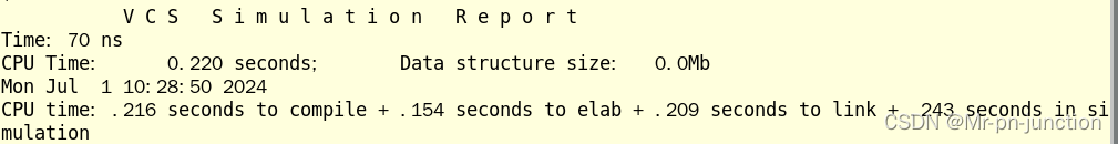
./tb_counter.v2 vcs编译
命令行:make run。如下所示:
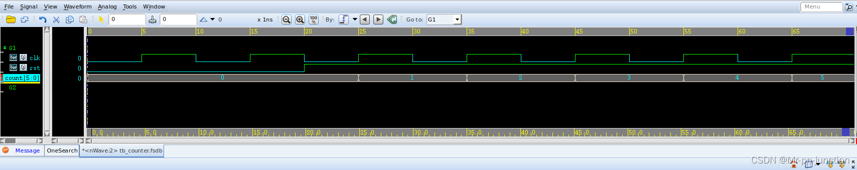
3 verdi查看波形
命令行:make verdi。点击信号,然后快捷键Ctrl+w将信号加入波形中。如下所示: