H3C GRE VPN基本配置实验
实验拓扑
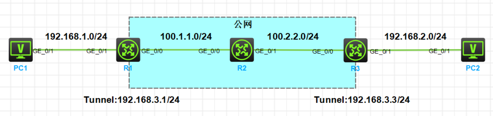
实验需求
- 按照图示配置 IP 地址
- 在 R1 和 R3 上配置默认路由使公网区域互通
- 在 R1 和 R3 上配置 GRE VPN,使两端私网能够互相访问,Tunnel 口 IP 地址如图
- 在 R1 和 R3 上配置动态路由协议来传递两端私网路由
实验步骤
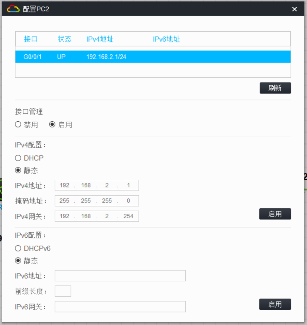
按照图示配置 IP 地址
shelll
[R1]display ip interface brief
*down: administratively down
(s): spoofing  (l): loopback
Interface           Physical Protocol IP address/Mask    VPN instance Description
GE0/0               up       up       100.1.1.1/24       --           --
GE0/1               up       up       192.168.1.254/24   --           --

[R2]display ip interface brief
*down: administratively down
(s): spoofing  (l): loopback
Interface           Physical Protocol IP address/Mask    VPN instance Description
GE0/0               up       up       100.1.1.2/24       --           --
GE0/1               up       up       100.2.2.2/24       --           --

[R3]display ip interface brief
*down: administratively down
(s): spoofing  (l): loopback
Interface           Physical Protocol IP address/Mask    VPN instance Description
GE0/0               up       up       100.2.2.3/24       --           --
GE0/1               up       up       192.168.2.254/24   --           --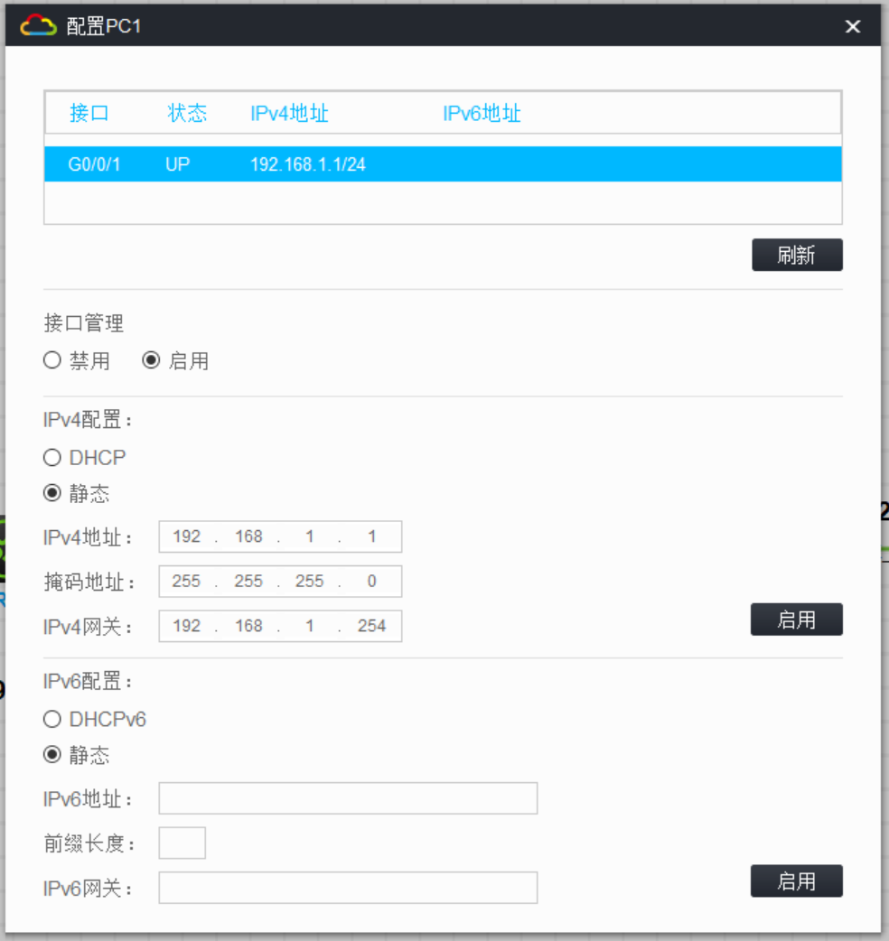
在 R1 和 R3 上配置默认路由使公网区域互通
shelll
[R1]ip route-static 0.0.0.0 0 100.1.1.2

[R3]ip route-static 0.0.0.0 0 100.2.2.2
在 R1 和 R3 上配置 GRE VPN,使两端私网能够互相访问
在R1上创建Tunnel口,模式为GRE,源地址和目的地址为本端公网地址和对端公网地址
shelll
[R1]interface Tunnel 0 mode gre 	//创建Tunnel口,模式为GRE
[R1-Tunnel0]ip address 192.168.3.1 255.255.255.0	//配置Tunnel0口IP地址
[R1-Tunnel0]source 100.1.1.1	//源地址为本端公网地址
[R1-Tunnel0]destination 100.2.2.3	//目的地址为对端公网地址

%Aug  1 09:46:31:195 2024 R1 IFNET/3/PHY_UPDOWN: Physical state on the interface Tunnel0 changed to up.
%Aug  1 09:46:31:195 2024 R1 IFNET/5/LINK_UPDOWN: Line protocol state on the interface Tunnel0 changed to up.
在R3上创建Tunnel口,模式为GRE,源地址和目的地址为本端公网地址和对端公网地址
shelll
[R3]interface Tunnel 0 mode gre 	//创建Tunnel口,模式为GRE
[R3-Tunnel0]ip address 192.168.3.3 255.255.255.0	//配置Tunnel0口IP地址
[R3-Tunnel0]source 100.2.2.3	//源地址为本端公网地址
[R3-Tunnel0]destination 100.1.1.1	//目的地址为对端公网地址

%Aug  1 09:54:11:176 2024 R3 IFNET/3/PHY_UPDOWN: Physical state on the interface Tunnel0 changed to up.
%Aug  1 09:54:11:176 2024 R3 IFNET/5/LINK_UPDOWN: Line protocol state on the interface Tunnel0 changed to up.
在 R1 和 R3 上配置OSPF协议来传递两端私网路由
R1 和 R3 通过 RIP 来传递私网路路由,由于私网报文要通过 VPN 隧道口传输,所以需要把 Tunnel 口宣告进 RIP,使 R1 和 R3 通过 Tunnel 口传递路由
在 R1 上配置OSPF,宣告业务网段和 Tunnel 口网段
[R1]ospf 1
[R1-ospf-1]area 0.0.0.0
[R1-ospf-1-area-0.0.0.0]network 192.168.3.0 0.0.0.255
[R1-ospf-1-area-0.0.0.0]network 192.168.1.0 0.0.0.255
在 R3 上配置OSPF,宣告业务网段和 Tunnel 口网段
[R3]ospf 1
[R3-ospf-1]area 0.0.0.0
[R3-ospf-1-area-0.0.0.0]network 192.168.3.0 0.0.0.255
[R3-ospf-1-area-0.0.0.0]network 192.168.2.0 0.0.0.255
实验验证
查看R1和R3的OSPF邻居建立情况,R1和R3的OSPF邻居状态为FULL,并使用Tunnel0接口建立
shelll
[R1]display ospf peer

	 OSPF Process 1 with Router ID 192.168.3.1
               Neighbor Brief Information

 Area: 0.0.0.0
 Router ID       Address         Pri Dead-Time  State             Interface
 192.168.3.3     192.168.3.3     1   38         Full/ -           Tun0

[R3]display ospf peer

	 OSPF Process 1 with Router ID 192.168.3.3
               Neighbor Brief Information

 Area: 0.0.0.0
 Router ID       Address         Pri Dead-Time  State             Interface
 192.168.3.1     192.168.3.1     1   39         Full/ -           Tun0
查看R1和R3的IP路由表,双方的私网网段路由下一跳皆为Tunnel0接口
shelll
[R1]display ip routing-table
Destinations : 18	Routes : 18
Destination/Mask   Proto   Pre Cost        NextHop         Interface
0.0.0.0/0          Static  60  0           100.1.1.2       GE0/0
0.0.0.0/32         Direct  0   0           127.0.0.1       InLoop0
100.1.1.0/24       Direct  0   0           100.1.1.1       GE0/0
100.1.1.1/32       Direct  0   0           127.0.0.1       InLoop0
100.1.1.255/32     Direct  0   0           100.1.1.1       GE0/0
127.0.0.0/8        Direct  0   0           127.0.0.1       InLoop0
127.0.0.1/32       Direct  0   0           127.0.0.1       InLoop0
127.255.255.255/32 Direct  0   0           127.0.0.1       InLoop0
192.168.1.0/24     Direct  0   0           192.168.1.254   GE0/1
192.168.1.254/32   Direct  0   0           127.0.0.1       InLoop0
192.168.1.255/32   Direct  0   0           192.168.1.254   GE0/1
192.168.2.0/24     O\_INTRA 10  1563        192.168.3.3     Tun0
192.168.3.0/24     Direct  0   0           192.168.3.1     Tun0
192.168.3.1/32     Direct  0   0           127.0.0.1       InLoop0
192.168.3.255/32   Direct  0   0           192.168.3.1     Tun0
224.0.0.0/4        Direct  0   0           0.0.0.0         NULL0
224.0.0.0/24       Direct  0   0           0.0.0.0         NULL0
255.255.255.255/32 Direct  0   0           127.0.0.1       InLoop0


[R3]display ip routing-table

Destinations : 18	Routes : 18

Destination/Mask   Proto   Pre Cost        NextHop         Interface
0.0.0.0/0          Static  60  0           100.2.2.2       GE0/0
0.0.0.0/32         Direct  0   0           127.0.0.1       InLoop0
100.2.2.0/24       Direct  0   0           100.2.2.3       GE0/0
100.2.2.3/32       Direct  0   0           127.0.0.1       InLoop0
100.2.2.255/32     Direct  0   0           100.2.2.3       GE0/0
127.0.0.0/8        Direct  0   0           127.0.0.1       InLoop0
127.0.0.1/32       Direct  0   0           127.0.0.1       InLoop0
127.255.255.255/32 Direct  0   0           127.0.0.1       InLoop0
192.168.1.0/24     O_INTRA 10  1563        192.168.3.1     Tun0
192.168.2.0/24     Direct  0   0           192.168.2.254   GE0/1
192.168.2.254/32   Direct  0   0           127.0.0.1       InLoop0
192.168.2.255/32   Direct  0   0           192.168.2.254   GE0/1
192.168.3.0/24     Direct  0   0           192.168.3.3     Tun0
192.168.3.3/32     Direct  0   0           127.0.0.1       InLoop0
192.168.3.255/32   Direct  0   0           192.168.3.3     Tun0
224.0.0.0/4        Direct  0   0           0.0.0.0         NULL0
224.0.0.0/24       Direct  0   0           0.0.0.0         NULL0
255.255.255.255/32 Direct  0   0           127.0.0.1       InLoop0
效果测试:在 PC1 上 Ping PC2,可以 Ping 通
<H3C>ping 192.168.2.1
Ping 192.168.2.1 (192.168.2.1): 56 data bytes, press CTRL_C to break
56 bytes from 192.168.2.1: icmp_seq=0 ttl=253 time=2.303 ms
56 bytes from 192.168.2.1: icmp_seq=1 ttl=253 time=2.750 ms
56 bytes from 192.168.2.1: icmp_seq=2 ttl=253 time=2.742 ms
56 bytes from 192.168.2.1: icmp_seq=3 ttl=253 time=1.045 ms
56 bytes from 192.168.2.1: icmp_seq=4 ttl=253 time=1.954 ms

--- Ping statistics for 192.168.2.1 ---
5 packet(s) transmitted, 5 packet(s) received, 0.0% packet loss
round-trip min/avg/max/std-dev = 1.045/2.159/2.750/0.631 ms
<H3C>%Aug  1 10:24:14:215 2024 H3C PING/6/PING_STATISTICS: Ping statistics for 192.168.2.1: 5 packet(s) transmitted, 5 packet(s) received, 0.0% packet loss, round-trip min/avg/max/std-dev = 1.045/2.159/2.750/0.631 ms.
实验附件
通过百度网盘分享的文件:H3C GRE VPN基本配置实验.zip
链接:https://pan.baidu.com/s/1ro9FRmPqMO3_XfnlWOhvSg?pwd=8ee7