Verilog中延时和时序检查
- [1. 延时模型](#1. 延时模型)
-
- [1.1 分布延迟](#1.1 分布延迟)
- [1.2 集总延迟](#1.2 集总延迟)
- [1.3 路径延迟](#1.3 路径延迟)
- [2. specify 语法](#2. specify 语法)
|---|
| |
1. 延时模型
真实的逻辑元器件和它们之间的互连线上都会有延时的存在。虽然 Verilog 设计主要考虑的是逻辑功能的正确性,但是 Verilog 语法是支持定义延时的。
Verilog 中延时模型有三种:分布延迟、集总延迟(lumped) 和路径延迟。
1.1 分布延迟
分布延迟指的是给电路中每个独立的元件进行延迟定义,不同的路径有不同的延时,如下图所示。
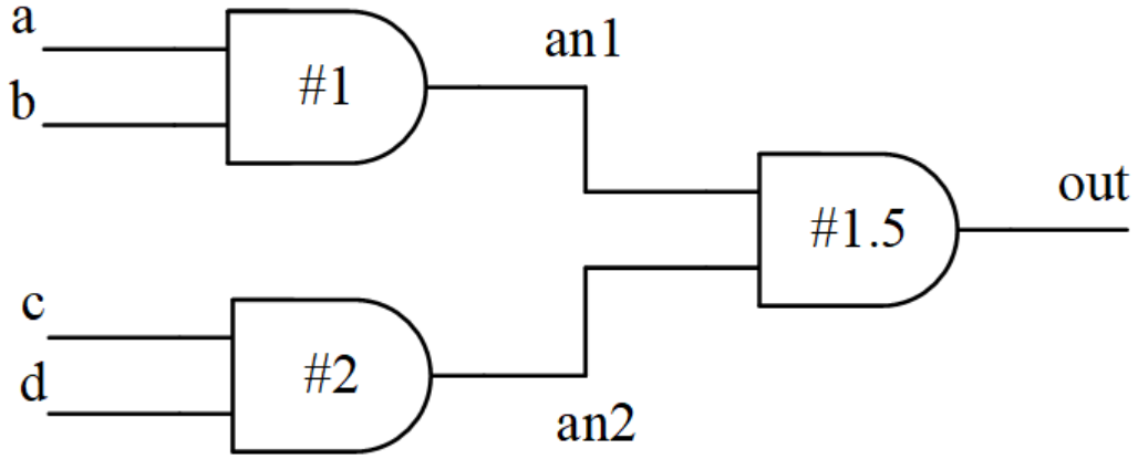
对应的 verilog 描述为:
cpp
// 例化逻辑门单元的时候指定延时
module and4(
output out,
input a, b, c, d);
wire an1, an2 ;
and #1 (an1, a, b);
and #2 (an2, c, d);
and #1.5 (out, an1, an2);
endmodule
// assign 语句中指定延时
module and4(
output out,
input a, b, c, d);
wire an1, an2 ;
assign #1 an1 = a & b ;
assign #2 an2 = c & d ;
assign #1.5 out = an1 & an2 ;
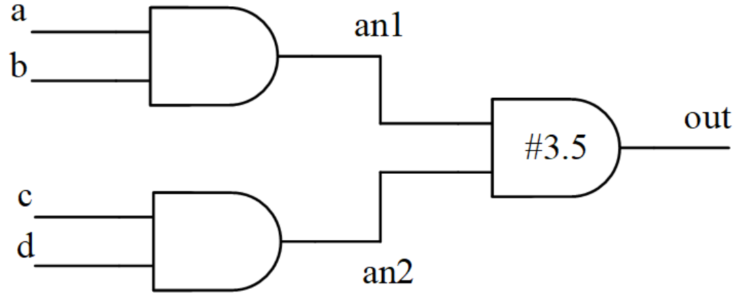
endmodule1.2 集总延迟
集总延迟是将全部路径累计的延时集中到最后一个门单元上。
到最后一个门单元上的延迟会因路径的不同而不同,此时取最大延时作为最后一个门单元的延时。
将上述分布延迟图转化为集总延迟图,如下所示。
对应的 verilog 描述如下:
cpp
module and4(
   output       out,
   input        a, b, c, d);

   wire         an1, an2 ;
   and          (an1, a, b);
   and          (an2, c, d);
   and #3.5     (out, an1, an2); //set the max delay at the last gate
endmodule
1.3 路径延迟
路径延迟是对每个输入端口(input ports)到每个输出端口(output ports)的所有路径指定延迟时间。
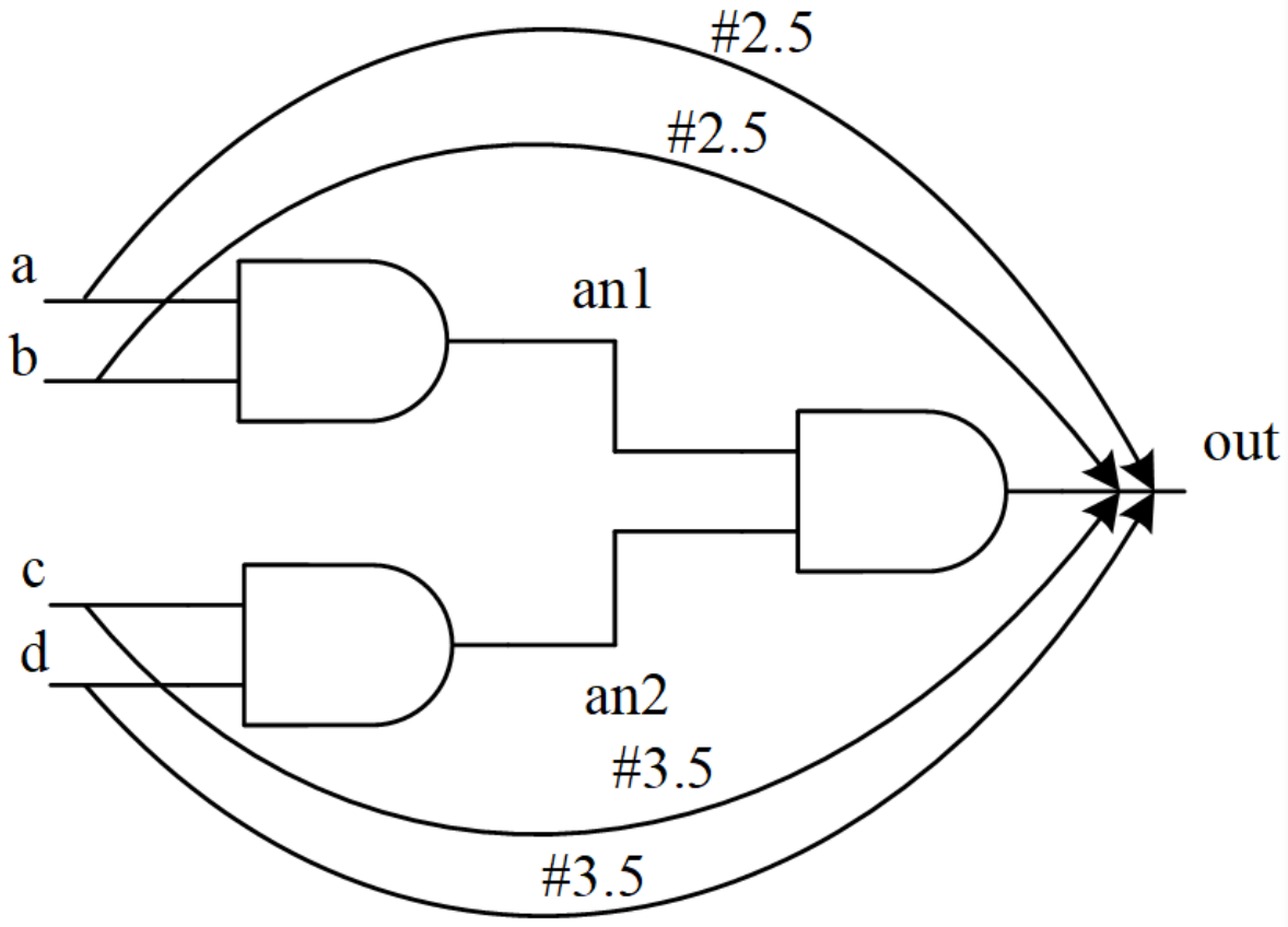
路径延迟模型需要使用 specify 关键字来定义,上图对应的 verilog 描述如下所示:
cpp
module and4(
   output       out,
   input        a, b, c, d);

   specify
      (a => out) = 2.5 ;
      (b => out) = 2.5 ;
      (c => out) = 3.5 ;
      (d => out) = 3.5 ;
   endspecify

   wire         an1, an2 ;
   and          (an1, a, b);
   and          (an2, c, d);
   and          (out, an1, an2);
endmodule
|---|
| |
2. specify 语法
Verilog 中的路径延迟使用 specify 块语句来描述,从 specify 为开始,到 endspecify 结束。
specify 是 module 中独立的一部分,不能出现在其他语句块(initial, always 等)中。
specify 块语句的主要功能是:指定所有路径中引脚到引脚的延迟、在电路中设置时序检查。
2.1 指定路径延时
基本路径延时
specify 块语句有两种基本的语法来定义延时:
方法一: 并行连接,每条路径都有一个源引脚和目的引脚,将这些路径的延迟依次用 specify 语句描述出来。
基本语法为:
cpp
(<source_io> => <destination_io>) = <delay_value>;一个带有路径延时的 4 输入与门的 verilog 描述如下:
cpp
module and4(
   output       out,
   input        a, b, c, d);

   specify
      (a => out) = 2.5 ;
      (b => out) = 2.5 ;
      (c => out) = 3.5 ;
      (d => out) = 3.5 ;
   endspecify

   wire         an1, an2 ;
   and          (an1, a, b);
   and          (an2, c, d);
   and          (out, an1, an2);
endmodule
在使用 specify 定义路径延时的时候,也可以定义参数,如下所示:
cpp
specify
   specparam ab_2_out = 2.5 ;
   specparam cd_2_out = 3.5 ;

   (a => out) = ab_2_out ;
   (b => out) = ab_2_out ;
   (c => out) = cd_2_out ;
   (d => out) = cd_2_out ;
endspecify需要注意的是,specparam 只能在 specify 内部声明及使用,而 parameter 只能在 specify 语句块的外部声明及使用。
在并行连接中,源引脚和目的引脚是一一对应的。并行连接也支持多位宽信号间的路径延迟描述,但是位宽必须保持一致。
cpp
module paral_conn(
    input [3:0]         d,
    output [3:0]        q);

   specify
      (d => q) = 3 ;
   endspecify

   assign q = d & 0101 ;
endmodule
上例的路径延时定义等价于:
cpp
specify
   (d[0] => q[0]) = 3 ;
   (d[1] => q[1]) = 3 ;
   (d[2] => q[2]) = 3 ;
   (d[3] => q[3]) = 3 ;
endspecify
方法二: 全连接,源引脚中的每一位与目标引脚的每一位相连接。源引脚和目的引脚的连接是组合遍历的,且不要求位宽对应。
基本语法为:
cpp
(<multiple_source_io> *> <multiple_destination_io>) = <delay_value> ;如下所示,4 输入的与逻辑模块的路径延时可以为:
cpp
module and4(
   output       out,
   input        a, b, c, d);

   specify
      (a,b *> out) = 2.5 ;
      (c,d *> out) = 3.5 ;
   endspecify

   wire         an1, an2 ;
   and          (an1, a, b);
   and          (an2, c, d);
   and          (out, an1, an2);
endmodule
边沿敏感路径延时
边沿敏感路径延时用于对时序电路的输入到输出延迟进行建模,需要使用边缘标识符指明触发条件。如果没有指明的话,任何变化都会触发源引脚到目的引脚的延迟值的变化。
示例1:
cpp
(posedge clk => (out +: in)) = (1,2);在 clk 的上升沿,对于从 clk 到 out 的路径,其上升延时是 1,下降延时是 2。+: 的意思是 in 到 out 的数据路径是同向传输,即 out = in。
示例2:
cpp
(negedge clk => (out -: in)) = (1,2);在 clk 的下降沿,对于从 clk 到 out 的路径,其上升延时是 1,下降延时是 2。-: 的意思是 in 到 out 的数据路径是反向传输,即 out = ~in。
示例3:
cpp
(negedge clk => (out : in)) = (1,2);clk 的任何变化,从clk到out的模块路径,其上升延时是1,下降延时是2,从in到out的数据路径的传输是不可预知的,同向或者反向或者不变。
状态依赖路径延时
Verilog 也允许模型中根据信号值的不同,有条件的给路径延迟进行不同的赋值。
一个简单的示例如下所示:
cpp
specify
   if (a)    (a => out) = 2.5 ;
   if (~a)   (a => out) = 1.5 ;

   if (b & c)        (b => out) = 2.5 ;
   if (!(b & c))     (b => out) = 1.5 ;

   if ({c, d} == 2'b01)
             (c,d *> out) = 3.5 ;
   ifnone    (c,d *> out) = 3 ;
endspecify
需要注意的是:
if语句的操作数可以是标量,也可以是向量,条件表达式也可以包含任意操作符;- 所有输入状态都应该说明,否则没有说明的路径使用分布延时,如果也没有声明分布延时的话,那么使用零延时(zero delay)。如果路径延时和分布延时同时声明的话,则选择最大的延时作为路径延时;
- 可以使用
ifnone语句,在其它所有条件都不满足的情况下,说明一个缺省的状态依赖路径延时。
2.2 时序检查
使用 specify 指定路径延迟之后,可以让仿真的时序更加接近实际数字电路的时序。
除此之外,specify 还可以定义一些系统任务,用来进行时序检查。
Verilog 中常用的用于时序检查的系统任务包括:$setup, $hold, $recovery, $removal, $widt, $period,这些系统任务只能在 specify 块中调用。
setup, hold, $setuphold
$setup 用来进行建立时间检查,$hold 用来进行保持时间检查,基本语法格式如下:
cpp
$setup(data_event, reference_event, limit, notifier);data_event:被检查的信号,判断它是否违反约束
reference_event:用于检查的参考信号,一般为时钟信号的跳变沿
limit:最小建立时间
当 reference_event time - limit < data_event time < reference_event time 的时候,仿真的时候会打印出 Timing Violation 的报告。
cpp
$hold (reference_event, data_event, limit, notifier);当 reference_event time < data_event time < reference_event time + limit 的时候,仿真的时候会报告 Hold Timing Violation。
这里需要注意的是,$setup 和 $hold 中输入端口的位置是不一样的。setup 检查中,数据要先到,hold 检查中,数据要晚走,所以可以按照事件的事件顺序来记忆。
此外,Verilog 还提供了同时检查setup 和 hold 的系统任务:
cpp
$setuphold (reference_event, data_event, setup_limit, hold_limit, notifier)该系统函数等价于:
cpp
$setup(data_event, reference_event, setup_limit, notifier);
$hold (reference_event, data_event, hold_limit, notifier);
当 reference_event time - setup_limit < data_event time < reference_event time + hold_limit 的时候,仿真的时候会报时序违例。
recovery, removal, $recrem
对于异步复位的触发器来说,异步复位信号也需要满足 recovery time(恢复时间)和 removal time(去除时间),才能有效的复位和释放复位,防止出现亚稳态。
$recovery, $removal, $recrem 的基于语法如下:
cpp
$recovery (reference_event, data_event, limit, notifier);reference_event:用于检查的参考信号,一般为清零或复位信号跳变沿;
data_event:被检查的信号,一般为时钟信号跳变沿。
limit:设置的最小 removal time。
当data_event time - limit(clk) < reference_event time(async rst) < data_event time(clk) 时,就会报告recovery time violations。
cpp
$removal (reference_event, data_event, limit, notifier);当 data_event time < reference_event time < data_event time + limit时,就会报告removal time violations。
cpp
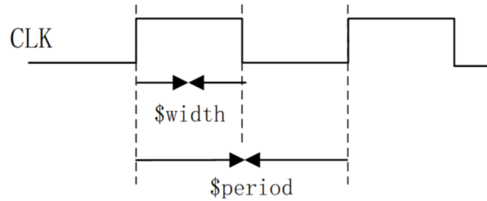
$recrem (reference_event, data_event, recovery_limit, removal_limit, notifier)width, period
有些数字设计,例如 flash 存储器,还需要对脉冲宽度或周期进行检查,为此 Verilog 分别提供了系统任务 $width 和 $period。用法如下:
cpp
$width (ref_event, time_limit, notifier);

$period(ref_event, time_limit, notifier);
ref_event :边沿触发事件
time_limit:脉冲的最小宽度
这里data_event是隐含的,它等于reference_event的相反边沿。
$width 用于检查边沿触发事件 ref_event 到下一个反向跳变沿之间的时间,常用于脉冲宽度的检查。如果两次相反跳边沿之间的时间小于 time_limit,则会报告 violation。
$period 用于检查边沿触发事件 ref_event 到下一个同向跳变沿之间的时间,常用于时钟周期的检查。如果两次同向跳边沿之间的时间小于 time_limit,则报告中会打印 violation。
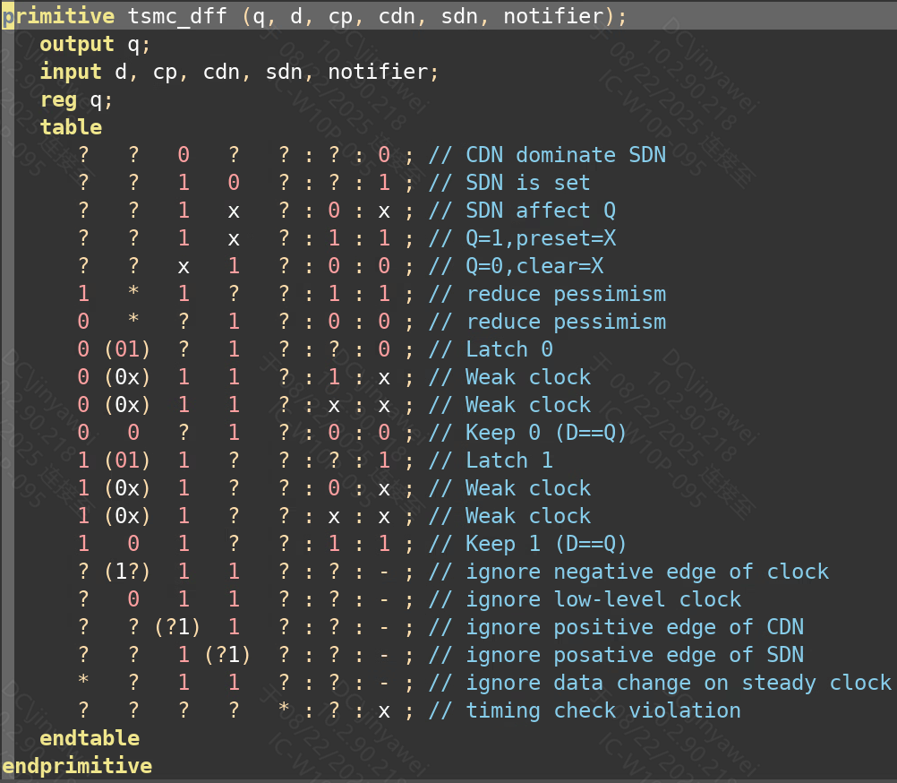
notifier
任意一条 timing check 语句检测到timing violation发生时,对应的 timing check 语句就会把 notifier 的值做一次 toggle。
notifier 的初始默认值是 x,第1次 timing violation 时,notifier 的值会从x变为0或1。后续每发生一次 timing violation,notifier 的值也会被做一次toggle。如果旧值为0,则新值为1。如果旧值为1,则新值为0。
notifier 的 toggle,会导致寄存器的Q端变为 x。
如下图所示,notifier 是 dff 的一个输入端口,当前发生任意跳变的时候,dff 的输出都将变为 x 态。