作者:张华 发表于:2015-06-11
版权声明:可以任意转载,转载时请务必以超链接形式标明文章原始出处和作者信息及本版权声明
(http://blog.csdn.net/quqi99 )
今天整理机器时发现下列文档,想当年对Power,对光纤存储,对光纤交换机,对AIX这些东西都算非常熟悉的了, 按老板的话说,都算go-to person了,呵呵。不过才三年没到,今天看到这些文档感觉好陌生,全忘干净了,要不停地与记忆作斗争,所以我选择把它放在博客上。现在我已经看不懂了,所以格式还是当时记笔记的样子,很乱。
也算对Power非常熟悉的了,才三年没到,
IP
网线
串口线
vios光盘
debug:
1 schedule 与POWERware调用流程
消息中间件Apache Qpid 简介
http://www.ibm.com/developerworks/cn/opensource/os-cn-qpid1/
启动qpid:qpidd --port=60302 --no-data-dir --auth=no 流程:
1)使用下列配置,$nova/nova/compute/manager.py会启动PowerVMDriver
compute_driver=powervm.PowerVMDriver
powervm_mgr_type=ivm
powervm_mgr=9.125.13.97
powervm_vios=powervm_mgr
powervm_mgr_user=padmin
powervm_mgr_passwd=padmin
powervm_img_remote_path=/home/padmin
powervm_img_local_path=/bak/openstack/glance/images
service_down_time=99999
- PowerVMDriver中的update_available_resource()方法会周期性更将状态**.**这个方法会根据数据庫的compute_nodes表去来刷新每个计算节点的下列信息:
vcpus
memory_mb
local_gb
vcpus_used
memory_mb_used
local_gb_used
hypervisor_type
hypervisor_version
cpu_info
cpu_arch
service_id
-
然后根据上述信息选取一个host,如hua.cn.ibm.com
-
然后会通过MQ给comput.hua.cn.ibm.com 这个****topic 发一个消息**,**(kombu + qpid )
-
hua.cn.ibm.com这个计算节点上的nova-compute服务收到消息之后就会根据传过来的参数调用相应的回调函数.
schdule的启动,在$nova/nova/service.py中有,它由nova-compute调用(nova-compute 这种服务启动时会往数据庫的表的 service 表放数据):
rpc_dispatcher=self.manager.create_rpc_dispatcher()
#Share this same connection for these Consumers
self.conn.create_consumer(self.topic,rpc_dispatcher,fanout=False)
node_topic**='%s.%s'%****(self.topic,self.host)**
self.conn.create_consumer(node_topic,rpc_dispatcher,fanout=False)
self.conn.create_consumer(self.topic,rpc_dispatcher,fanout=True)
#Consume from all consumers in a thread
self.conn.consume_in_thread()
1 keystone
Keystone是一款认证服务,有两大功能:基于token的认证(authentication,即authN)与和基于用户-服务的授权(authorization,即authZ),可以连接外部认证系统如LDAP。未来还将支持oAuth,SAML, openID。
sudo yum install openldap
2 glance
4 IaaS openstack-based implementation
The following is a list of the major functional areas for theSmartCloud IaaS API:
-
Metering & Billing
5 IVM环境搭建
结合使用集成虚拟化管理器和Linux on POWER
http://www.ibm.com/developerworks/cn/linux/l-pow-ivm/index.html?S_TACT=105AGX52&S_CMP=tech-51CTO
采用HMC时,是从HMC上安装VIOS,VIOS自带了IVM.对于Powerblade, 它有管理控制台,可让你安装VIOS.但对于普通的Power在没有HMC的情况下如何安装VIOS呢?答案是要将非托管的配置转换为IVM 托管的系统,需要将VIOS 安装在非托管系统中的第一个分区上。
5.1 IVM托管的系统的安装和配置& VIOS的安装
我门一直没搞成的原因是:
-
- Power
用串口线(即null modem)将PC机与power的串行端口1相連.此外还要用网线直連。执行以下步骤,完成灵活的服务处理器(FSP)的初始化和VIOS 的安装。
Linux下的串口超级终端,sudo yum install minicom && sudo yum install lrzsz
1,开始配置:minicom -s , 将终端应用程序的连接设置为每秒19200位,8数据位,无奇偶校验,1停止位。SerialDevice要配置为串口一/dev/ttyS0.但是笔記本无串口,一般是power那端是串口,笔記本这端是USB口,那得改成/dev/ttyUSB0 . 用lsmod| grep usbserial 命令可以查看系统是否支持USB转串口.
2,启动系统并在终端上按下一个键,以获得服务处理器的提示。
3,使用用户ID admin和默认密码 admin登录。当提示更改用户密码时,则修改
4,通过NetworkServices > Network Configuration > Configure interface Eth0设置IP,如10.10.10.109
5,登录AdvancedSystems Management interface,ASMI, https://10.10.10.109
6,在导航区选择System Configuration > TimeOf Day 。根据 UTC时间输入数据和时间。单击Save Settings 。
注意: 可以在http://tycho.usno.navy.mil/cgi-bin/timer.pl找到当前的 UTC时间。
7,选择Power/Restart Control >Power On/Off System 。在 Bootto system server firmware 中,选择Standby ,并单击 Save settings and poweron 。启动并引导系统服务固件到 standby 模式
8,启动系统需等待几分钟。如果重新显示PowerOn/Off System 页面,当前的系统服务固件应该处于"standby"状态。选择On Demand Utilities > CoDActivation ,为 AdvancedPower Virtualization 输入CoD激活码,然后单击Continue 。 ( 激活码 ?)
安装VIOS,现在已经安装好了FSP,可以对VIOS进行安装和设置了。这仍将用到连接到系统串行端口的PC上的串行终端应用程序。
1,放入VIOS光盘到光驱中,在ASMIWeb 界面选择Power/Restart Control >Power On/Off System 。选择 Running来启动系统服务器固件,单击Save settings and power on.
2,等待串行终端的提示并按下0来选择活动的控制台。
3,等待启动屏幕出现在串行控制台。当显示字符键盘时快速按下1进入SMS(SystemManagement Services)菜单。
4,当显示提示时,输入admin用户帐号的密码。
5,显示SMS主菜单后,选择以下SMS选项:SelectBoot Options > Select Install/Boot Device > List all Devices >IDE CD-ROM (如果驱动是SCSICD 或DVD的话则使用SCSICD-ROM)。
6,开始安装...
7,查看与接受协议,license --view && license -accept
8,创建VIOS虚拟以太网接口,mkgencfg -o init
9,要找到可用于服务器的外部网络连接的以太网接口lsdev|grep ent
10,配置IVMIP, mktcpip -hostname IBMOP_VIO -inetaddr 10.10.10.110 -interface en0\
-netmask 255.255.255.0 -gateway 10.10.10.1 –start
      之后, 在IVM里可以配SEA, 这将会将eth0上的IP移到SEA卡上.
11, 登录IVM,http://10.10.10.110 http://9.125.13.97
如何建SEA卡,SEA卡起到网桥的作用?
如何建VLAN?
如何建存储池?安装VIOS后,它所在的叫rootvg,可将其他的磁盘新建一个VG.
5.2 v7000与power的配置
https://9.125.13.61 npiv / npivnpiv
IBMV7000安装配置http://wendang.baidu.com/view/aa573c49c850ad02de8041fc.html
IBM_V7000配置实施文档(图文并茂)http://wendang.baidu.com/view/1963ac76f46527d3240ce096.html
术语:
Mdisk: 被管理的硬盘
StoragePool,由一个或多个Mdisk組成的存储空间
Volumes,由池中创建的存储空间,提供给主机使用(lun)
首先应该用两根光纤将v7000与power通过光纤交換机连起来.
其次应该在光纤交換机中配置Zone
最后,在v7000的配置中也要为power建host(因为磁盘要和host关联嘛)
1, 安装上架,連线,加电
2, 用USBkey初始化v7000,给它配置IP.
3, 创建Mdisk(也即创建Raid),例12块SAS硬盘,存储会推荐分别用6块和5块创建2个raid5(即2个mdisk),另外一块作hotspare
4, 创建Pools,(即将创建的Raid划给Pool),Pools -> Internal Storage -> Configure Storage
5, 创建host,会关联power的光纤卡的一个port的WWPN号
6, 在pool上创建volume,并将volume关联到host
创建volume,svctask mkvdisk -cache readwrite -copies 1 -iogrp io_grp0 -mdiskgrpmdiskgrp0 -name test99 -size 1 -syncrate 50 -unit gb -vtype striped
删除volume,svctask rmvdisk 242
将volume映射到host,svctask mkvdiskhostmap -force -host 4 -scsi 1 242
unmap, svctask rmvdiskhostmap -host 4 242
7, 在v7000端映射成功后,在主机端执行#cfgmgr-v 扫描新的物理设计将硬盘扫描出来
5.3Power中的网络虚拟化
1) PVID 只是 Power 内部用的, 内部通过 Mac 或PVID转发包。 如VIOS的PVID设置的PVID=1,那么LPAR中只要PVID=1的包都能出去。 出去了之后的包的PVID是被剥离的。V LANID 是另一个概念 .
2) Lpar 可以直接用物理网卡, 不用VIOS
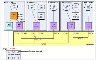
PortVLAN ID (PVID), 交換机的端口有PVID,如果带有VLANtags的包过来和PVID不同的话就丢弃了.如果过来一个没有VLANtags的包就给它加上VLANtags并转给相应的端口.(这样路由就不再只根据子网来了,而且需要根据VLANID来).
虚拟网卡通过SEA卡访问外网,SEA卡是将一个物理网卡与虚拟网卡绑定,它相当于网桥的作用.
How to work with VLAN using VIOS
http://www.torontoaix.com/vio-how-to-s/how-to-work-with-vlan-using-vios
- 在VIOS中的虚拟网卡ent2,可以添加多个vlanids, 如下图:
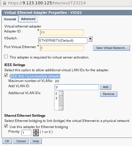
- 利用上述虚拟网卡ent2建立SEA设备的命令如下,它将创建SEA卡ent3.
mkvdev-sea ent0 -vadapter ent2 -default ent2 -defaultid 1
3)让SEA卡ent3成为trunk卡,Allow the SEA to transmit packets for many VLANs
mkvdev -vlan ent3 -tagid 1 ( Configuring a Shared Ethernet Adapter,http://pic.dhe.ibm.com/infocenter/powersys/v3r1m5/index.jsp?topic=/iphc3_p5/iphc3_vios_configuring_sea.htm)
mkvdev -vlan ent3 -tagid 2
mkvdev -vlan ent3 -tagid 3
- 为SEA卡配置IP,mktcpip-hostname op34 -inetaddr 9.137.62.34 -interface en3 -netmask
255.255.255.0 -gateway 9.137.62.1
smit tcp_ip-
-
当然也可以让这个VIOS中的虚拟网卡ent2有多个组成负载均衡.
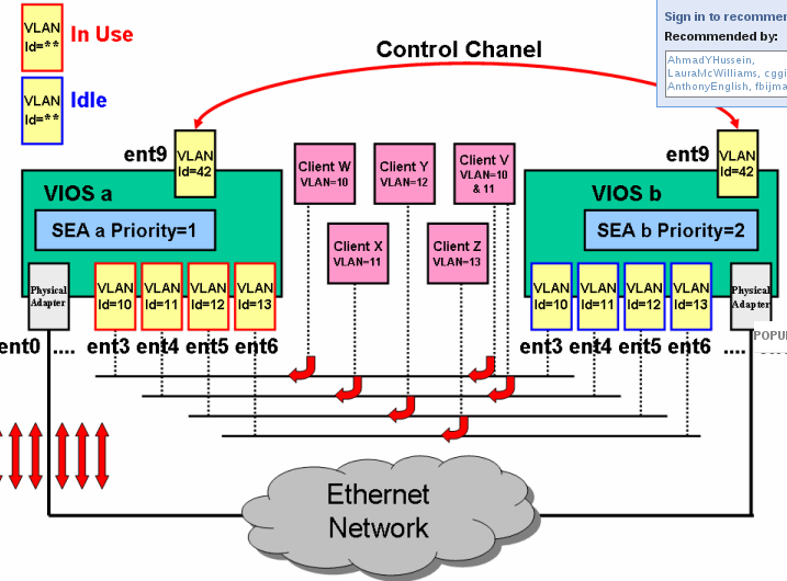
mkvdev -sea ent0 -vadapter ent2, ent3,ent4,ent5, ent6 -default ent3 -defaultid=10 -attr ha_mode=autoctl_chan=ent42
-
-
-
现在的问题是两台power上具有相同vlan的两个虚机如何互訪.
首先SEA本身是trunk的,那么需要将物理交换机的连接端口也配成trunk或配置让那个vlan可通过(我想这也是为什么我上次跨物理机的两个 linuxbridge 上的两个虚机无法互通的原因)交换机VLAN的配置------跨交换机实现VLAN通信
http://blog.sina.com.cn/s/blog_622de9390100indp.html这个想法在下列网页得到了証实,nova-networkVlan 模式配置http://www.openstack.org.cn/bbs/forum.php?mod=viewthread&tid=285
设置1516 17 18四个以太网接口为trunk 模式( 其中1516 17 18四个以太网接口分别连接3个compute node 和network controller 的eth1。),并创建两个vlan。
-
sina>enable
sina#configure terminal
sina(config-if)#interfaceGigabitEthernet0/15
sina(config-if)#switchport modetrunk
sina(config-if)#interfaceGigabitEthernet0/16
sina(config-if)#switchport modetrunk
sina(config-if)#interfaceGigabitEthernet0/17
sina(config-if)#switchport modetrunk
sina(config-if)#interfaceGigabitEthernet0/18
sina(config-if)#switchport modetrunk
sina(config-if)#exit
sina(config)#vlan 100
sina(config-vlan)#exit
sina(config)#vlan 101
sina(config-vlan)#exit
sina(config)#exit
sina#write
switchport mode trunk

switchport trunk native vlan 1 (This is the vlan that un-tagged packets will go to..)
switchport trunk allowed vlan 100-115 (Since you created 16 networks, they will be vlan's 100-115)
/etc/nova/nova.conf
--network_manager=nova.network.manager.VlanManager
--vlan_interface=eth1
sudo nova-manage network create public192.168.100.0/24 1 256
sudo nova-manage networkcreate public 192.168.101.0/24 1 256
mysql> use nova;
mysql>update networks set vlan="100″ where cidr="192.168.100.0/24″;
mysql> update networks set vlan="101″ wherecidr="192.168.101.0/24″;
-
- 在power的一个lpar上安装openstack的话,存在在虚拟网絡中再配一层虚拟网絡的问题.需采用openstack的multi-host模式安装
IVM and VLAN Tagging ,https://www.ibm.com/developerworks/mydeveloperworks/blogs/cgaix/entry/ivm_and_vlan_tagging1?lang=en
$lsdev -virtual
ent8 Available Shared Ethernet Adapter
$ r o
oem_setup_env
# lsattr -El ent8
accounting disabled Enable per-client accounting of networkstatistics True
ctl_chan Control Channel adapter for SEA failover True
gvrp no Enable GARP VLAN Registration Protocol(GVRP) True
ha_mode disabled High Availability Mode True
jumbo_frames no Enable Gigabit Ethernet Jumbo Frames True
large_receive no Enable receive TCP segment aggregation True
largesend 0 Enable Hardware Transmit TCP Resegmentation True
lldpsvc no Enable IEEE 802.1qbg services True
netaddr 0 Address to ping True
pvid 1 PVID to use for the SEA device True
pvid_adapter ent4 Default virtual adapter to use fornon-VLAN-tagged packets True
qos_mode disabled N/A True
real_adapter ent0 Physical adapter associated with the SEA True
thread 1 Thread mode enabled (1) or disabled (0) True
virt_adapters ent4 List of virtual adapters associated withthe SEA (comma separated) True
$ entstat -all ent8 |grep -i vlan
VLAN Ids :
Invalid VLAN ID Packets: 0
Port VLAN ID: 1
**VLAN Tag IDs:**None
可见,The SEA was configured with Port-VLAN ID (PVID) of 1 without any VLANtags.
查看虚机在虚拟交換机上的端口(也就是slot),
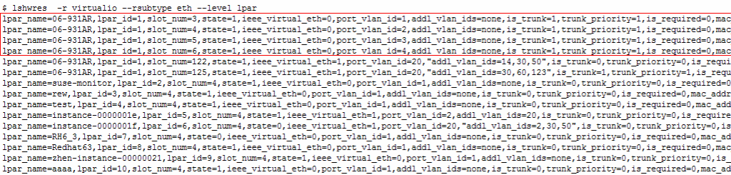
$ lshwres -r virtualio --rsubtype eth --level lpar
lpar_name=Powerblade_02_VIOS,lpar_id=1,slot_num=12 ,state=1,ieee_virtual_eth=0,port_vlan_id=1,addl_vlan_ids=none,is_trunk=1,trunk_priority=1,is_required=0,mac_addr=923BB8A11703
从端口12上删除网卡,然后在端口12上重新添加,并改变port_vlan_id和addl_valn_ids:
$chhwres -m Server-8406-71Y-SN06BF99Z -p 06-BF99Z -r virtualio--rsubtype eth -s 12 -o r
$chhwres -m Server-8406-71Y-SN06BF99Z -p 06-BF99Z -r virtualio--rsubtype eth -s 12 -o a -a"ieee_virtual_eth=1,port_vlan_id=11,addl_vlan_ids=68,is_trunk=1,trunk_priority=1"-d 5
$lshwres -r virtualio --rsubtype eth --level lpar
mkvdev-sea ent6 -vadapter ent2 -default ent2 -defaultid 1
entstat-all ent7 | grep -i vlan
$ mkvdev -vlan ent8 -tagid 2
ent9 Available
en9
et9
$ rmdev -dev ent9
,
所以服务端的虚拟网卡ent2相当于linux中的eth0.1000这样的vlan网卡,它与客户端的虚拟网卡应该位于同一vlan中.
检查所有网络映射关系, lsmap -all -net
设置vios服务器的IP地址,将IP设置在SEA卡en3上(也就是网桥上)
mktcpip-hostname VIO_Server1 -inetaddr 9.3.5.196 -interface en3 -netmask255.255.254.0 -gateway 9.3.4.1
不过在 ivm 上好像不用上面那么麻烦 , ** 直接在** ivm 界面上初始化虚拟网卡 , ** 就SEA和虚拟网卡自动都创建了**.
$lsmap -all -net
SVEA Physloc
ent10 U8202.E4C.069327R-V1-C3-T1
SEA ent14
Backingdevice ent2
Status Available
Physloc U78AA.001.WZSHH4H-P1-C1-C2-T1
5.4Power中的存储虚拟化
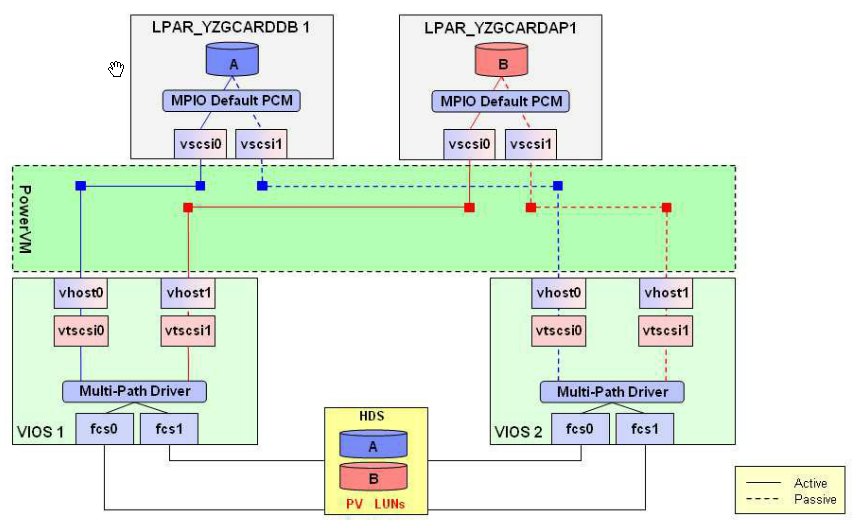
在VIOS端,安装相就的multi-path软件,使得SAN可以在VIOS通过多路径访问.
为了能够通过两个VIOS将同一块磁盘映射给AIX分苑,需在VIOS上修改磁盘的reserve_lock属性.
chdev -devhisk5 -attr reserve_policy=no_reserve
chdev -devhisk5 -attr
确定scsi虚拟设备号及vhost对应关系,lsdev -vpd|grep vhost
将虚拟硬盘分配给vhost,mkvdev -vdev hdisk5 -vadapter vhost0 -dev aix1-lun
lsmap-vadapter vhost0
将光驱映射到SCSI虚拟设备上,mkvdev -vdev cd0 -vadapter vhost4 -dev DVD
当光纤連好后, 创建ZONE. 搞好后, 在v7000里:
1) 创建host:
lsnports
lsdev -dev fcs3 -vpd |grep "Network Address"
svctask mkhost -force-hbawwpn 10000000C9D96037 -mask 1111 -name neon -type generic
-
创建 vdisk
svctask mkvdisk -cachereadwrite -copies 1 -iogrp io_grp0 -mdiskgrp mdiskgrp2 -name neon-size 1 -syncrate 50 -unit gb -vtype striped
-
attaching
svctask mkvdiskhostmap-force -host 193 -scsi 0 246
6如何做appliance
建立用于构建定制虚拟云映像的系统
http://www.ibm.com/developerworks/cn/cloud/library/cl-buildcloudimageICCT/
KVM不支持OVF,没有客户化参数的用户界面.
-
在 vm里头的/etc/rc.local加一个脚本
-
在 vm外头的host里加一个脚本, 通过kickstart去调.脚本在外面, 避免每改一下脚本就修改image.( virt-install --name myvm --ram 512 --diskpath=/test/myvm.img,size=3 --network=network=default,model=virtio--vnc --os-type=linux--location=http://download.fedoraproject.org/pub/fedora/linux/releases/14/Fedora/i386/os/--initrd-inject=/test/fedora14_custom.ks --extra-args"ks=file:/fedora14_custom.ks")
(initrd-inject 用于指定一个目录 , 将 host 里的文件注入到 guest 中去)
-
-
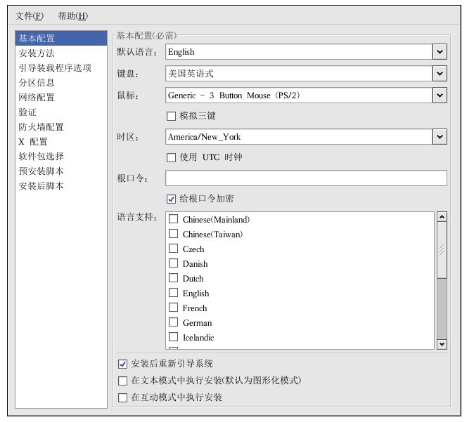 VSAE
VSAE -
vmware用VMWareTools实现同样的功能.
-
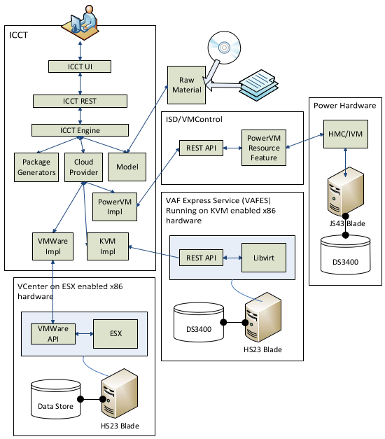
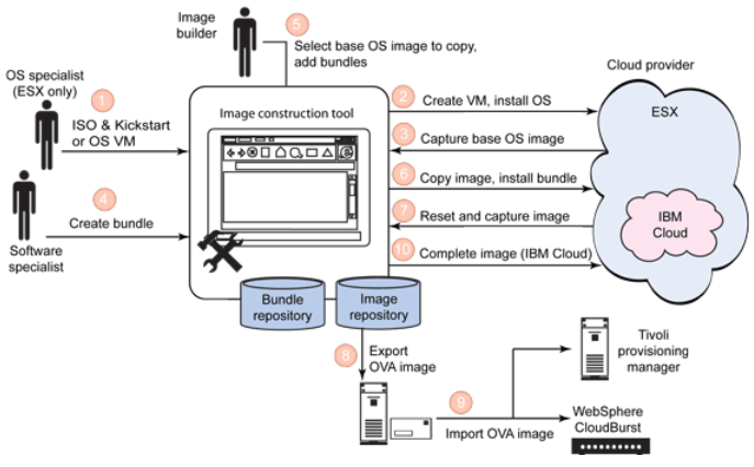
ImageConstruction and Composition Tool ,它自动在VM中安装VSAE, OVF将参数定义在一个virtualCD drive中的ovf-env.xml文件中,vm在启动后会mount这个virualCD drive. VSAE读配置检索参数然后调用相应的脚本去处理.
-
一个ovf-env.xml文件的例子.
-
<PropertySection>
<Propertyovfenv:key="com.ibm.vsae.2_1.db2-ese95-config.db2inst1_password"
ovfenv:value="s3cr3t"/>
/PropertySection>
解析函数 :
import os
from xml.dom.minidomimport parseString
def findXmlSection(dom,sectionName):
sections =dom.getElementsByTagName(sectionName)
return sections0
defgetPropertyMap(ovfEnv):
dom =parseString(ovfEnv)
section =findXmlSection(dom, "PropertySection")
propertyMap = {}
for property insection.getElementsByTagName("Property"):
key =property.getAttribute("oe:key")
value =property.getAttribute("oe:value")
propertyMapkey =value
dom.unlink()
return propertyMap
ovfEnv =open("d:\\ovf-env.xml", "r").read()
propertyMap =getPropertyMap(ovfEnv)
ip =propertyMap"ip"
netmask =propertyMap"netmask"
gateway =propertyMap"gateway"
dns1 =propertyMap"dns1"
dns2 =propertyMap"dns2"
name = "\"LocalArea Connection\""
# Set up IP
os.system("echonetsh interface ip set address %s static %s %s %s 0" % (name,ip, netmask, gateway))
# Set up preferred DNSserver
os.system("echonetsh interface ip set dns %s static %s" % (name, dns1))
# Set up alternate DNSserver
os.system("echonetsh interface ip add dns %s %s index=2" % (name, dns2))
VSAE是如何知道调用什么脚本去处理呢?这是由ActivationLogic (AL)去配置的.AL示例:
<?xml version="1.0"encoding="UTF-8"?>
<al2:Activationxmlns:al2="http://www.ibm.com/xmlns/ovf/activation/al/2">
<VirtualSystemid="vs0">1
<ProductActivationclass="com.ibm.vsae.2_1.db2-ese95-config">2
<Servicename="activate.db2-config">
<RunLevel value="5"/>
<RunLevel value="3"/>
</Service>
<ProgramcmdOptionStyle="longSpace" envVars="false"
href="AS/db2-config/activate.py"/>3
<OSServiceDependencyserviceName="network" start="after" />4
<ResetProgramhref="AS/db2-config/reset.py" />5
<Properties>6
<Propertykey="db2inst1_password" />
<Propertykey="db2inst1_username" />
<Propertykey="db2_hostname" />
</Properties>
</ProductActivation>
</VirtualSystem>
</al2:Activation>
VSAE所配置的基本参数是:
network-interface
system-host
dns-client
system-user
ntp-client
Image Construction andComposition Tool基于WebSpheresMash构建,用derby作数据庫.
6.1 OVF
在 centos6上创建Openstackcentos 5.4镜像
http://www.linuxwind.org/html/create-openstack-image-on-centos-6-2.html
http://blogs.vmware.com/vapp/2009/08/inside-the-ovf-package.html
6.2VSAE
scproot@9.123.100.141:/opt/ibm/director/proddata/activation-engine/vmc.vsae.tar.
1.disable Firewall
#setup
enter 'firewallConfiguration' anddisable firewall
2.disable SELinux
#setenforce 0
#vi /etc/selinux/config
SELINUX=disabled
6.1PADK
PADA是一个帮助创建,测试,验证VSAE( IBM Virtual Solutions Activation Engine)扩展的eclipse插件.
-
安装 pydev插件
-
安装 PADK插件, http://ICCThost:9099/padkp2repo
6.2Vmware
-
Self-Configurationand the OVF Environment
http://blogs.vmware.com/vapp/2009/07/selfconfiguration-and-the-ovf-environment.html
Define OVFproperties on theVM.
-
Setup the OVFenvironment transport to carry the settings into thevirtual machine.
-
Write some glue codeto access and apply the information inside the VM.
-
将自定义的配置配在 ovf的property元素中
-
通过 VMwareTools将配置(guestinfo.ovfEnv)传入虚机中. VMwaretools会将appliance作为一个CD-ROMmount进虚机之中.
7 HA &Load Balance
https://gitorious.rchland.ibm.com/~kpavel-il/openstack/kpavel-ils-nova
https://review.openstack.org/#/c/11086/
构建 OpenStack的高可用性(HA,HighAvailability)
http://blog.csdn.net/hilyoo/article/details/7704280
8 monitoring
https://review.openstack.org/#/c/10903/
http://wiki.openstack.org/ResourceMonitorAlertsandNotifications#Code_Changes
9 network
chhwres-r virtualio --rsubtype eth -o a --id 5 -s 4 -aport_vlan_id=90,\"addl_vlan_ids=78,79,3,4,5,6,7,8,9,21,23,24,25,56,67,89,87,34,32,35,36,32\",ieee_virtual_eth=1,is_trunk=1,trunk_priority=3
VIOSE01050133-0276The maximum number of additional virtual LAN IDs (addl_vlan_ids) thatmay be specified is 20. Virtual adapter defined for virtual slotnumber 4 specifies too many additional virtual LAN IDs.
weneed to change the PVID and additional VLAN ID for the network baseon our design
1.Forclient lpar, we can remove and add command to change a clent lparvlan properties, like that:
chhwres-r virtualio --rsubtype eth -o r --id 6 -s 4
chhwres-r virtualio --rsubtype eth -o a --id 6 -s 4 -aport_vlan_id=20,\"addl_vlan_ids=2,30,50\",ieee_virtual_eth=1
Butwe can change the vlan properties in HMC env, like that:
chhwres-r virtualio -m Server-8205-E6B-SN0622A1R -o s --rsubtype eth --id 10-s 3 -a \"addl_vlan_ids=2,30,50\" --force
pleaserefer to thelink:http://www.ibm.com/developerworks/forums/thread.jspa?threadID=370522
wecan not change the lpar vlan in IVM dynamically? but it works in HMC?
2.For the vio server, i can not change the exists vlan properties usingremove and add
$chhwres -r virtualio --rsubtype eth -o r --id 1 -s 4
VIOSE0105012E-0285Cannot modify or remove virtual adapters in virtual slot numbers lessthan 10 in the management partition.
alsocan not change:
$chhwres -r virtualio --rsubtype eth -o s --id 1 -s 4 -aport_vlan_id=29
VIOSE01040120-0006Required parameter -o or its value is missing or not valid.
sohow to change the exists vio server vlan properties?
Ican make a slot that number like 122 in vio, then I can change thevlan through remove or add vlan, I guess that is a walk round,
chhwres-r virtualio --rsubtype eth -o a --id 1 -s 122 -aport_vlan_id=20,\"addl_vlan_ids=14,30,50\",ieee_virtual_eth=1
Doyou agree with the above walk round?
ifso we can not using the following exist slot_num 3,4,5,6 toconfigurate our ENV,we need to create new vlan for vio server
Couldyou help us, thanks!
-
tun 得打开
-
br 网桥得设置成混杂模式,且用下列的 demsg 测试得物理网卡处在混模式, br 处在转发模式
root@jay-linux\~# dmesg
<! --- ..... -->
device eth0 entered promiscuous mode
br0: port 1(eth0) entered forwarding state
9.1 brocade B24Y交换机配置vlan
switch:admin> switchcfgtrunk1 //开启交换机的trunking 功能
switch:admin> portcfgtrunkport3, 1 //将 3号口加入trunking
switch:admin>trunkshow //查看trunking 状态
9.2 metadata service
Ip addr add 169.254.168.254/32 scope link dev lo
metadata_host=172.16.1.4
iptables -A nova-network-PREROUTING -d 169.254.169.254/32 -p tcp -m tcp --dport 80 -j DNAT --to-destination 172.16.1.4:8775Toallow instances to reach the metadata service, thenova-network servicewill configure iptables to NAT port 80 ofthe 169.254.169.254 addressto the IP address specified in metadata_host (default$my_ip,which is the IP address of the nova-network service)and port specified in metadata_port (default8775)in /etc/nova/nova.conf.
Lookslike we need similar nova-network implemenation for PowerVM. Worst case, we do in our nova-virt driver as part of init. Hereis what linux does:
def metadata_forward():
"""Createforwarding rule for metadata."""
if FLAGS**.metadata_host!=** '127.0.0.1':
iptables_manager**.ipv4'nat'.add_rule('PREROUTING',
'-s0.0.0.0/0 -d 169.254.169.254/32 '
'-ptcp -m tcp --dport 80 -j DNAT '
'--to-destination%s:%s' %
(FLAGS.metadata_host,
FLAGS.metadata_port))
else:
iptables_manager.ipv4'nat'.add_rule('PREROUTING',
'-s0.0.0.0/0 -d 169.254.169.254/32 '
'-ptcp -m tcp --dport 80 '
'-jREDIRECT --to-ports %s' %
FLAGS.metadata_port)
iptables_manager.**apply()
def metadata_accept():
"""Createthe filter accept rule for metadata."""
iptables_manager**.ipv4'filter'.add_rule('INPUT',
'-s0.0.0.0/0 -d %s '
'-ptcp -m tcp --dport %s '
'-jACCEPT' %
(FLAGS.metadata_host,
FLAGS.**metadata_port))
def init_host(ip_range**=None):
"""Basicnetworking setup goes here."""
#NOTE(devcamcar): Cloud public SNAT entries and the default
#SNAT rule for outbound traffic.
if not ip_range:
ip_range = FLAGS.**fixed_range
add_snat_rule(ip_range)
iptables_manager**.ipv4'nat'.add_rule('POSTROUTING',
'-s%s -d %s/32 -j ACCEPT' %
(ip_range, FLAGS.**metadata_host))
for dmzin FLAGS**.dmz_cidr:
iptables_manager.ipv4'nat'.**add_rule('POSTROUTING',
'-s%s -d %s -j ACCEPT' %
(ip_range, dmz))
iptables_manager**.ipv4'nat'.add_rule('POSTROUTING',
'-s%(range)s -d %(range)s '
'-mconntrack ! --ctstate DNAT '
'-jACCEPT' %
{'range':ip_range})
iptables_manager.**apply()
元数据可以注入或者通过元数据两种方式设置到VM中去。
http://allanx.blog.51cto.com/2849465/891053
对注入的支持可以有 loop,guestfs,nbd,mount 等,其中 mount 不安全。缺省使用 :
img_handlers="loop,nbd,guestfs"
对于nbd,在ubuntu下只需要加载内核模块(modprobe nbd)和安装qemu-nbd
在centos下就比较麻烦了,需要手工编译nbd和qemu-nbd
Guestfs方法比较简单,只需要安装正确的包就可以,ubuntu下安装guestmount, centos需要安装libguestfs和fuse
http://www.pubyun.com/blog/openstack/%E4%BB%80%E4%B9%88%E6%98%AFopenstack%E7%9A%84-metadata/
# Fetch public key using HTTP
ATTEMPTS=10
while [ ! -f /root/.ssh/authorized_keys ]; do
    curl -f http://169.254.169.254/latest/meta-data/public-keys/0/openssh-key > /tmp/aws-key 2>/dev/null
    if [ \$? -eq 0 ]; then
        cat /tmp/aws-key >> /root/.ssh/authorized_keys
        chmod 0600 /root/.ssh/authorized_keys
        restorecon /root/.ssh/authorized_keys
        rm -f /tmp/aws-key
        echo "Successfully retrieved AWS public key from instance metadata"
    else
        FAILED=\$((\$FAILED + 1))
        if [ \$FAILED -ge \$ATTEMPTS ]; then
            echo "Failed to retrieve AWS public key after \$FAILED attempts, quitting"
            break
        fi
        echo "Could not retrieve AWS public key (attempt #\$FAILED/\$ATTEMPTS), retrying in 5 seconds..."
        sleep 5
    fi
done
9 RPM
http://www.ibm.com/developerworks/cn/linux/management/package/rpm/part1/index.html
http://hi.baidu.com/greatren518/blog/item/f2fabb173df1da03c83d6d32.html
http://www.justwinit.cn/post/3794/
http://hlee.iteye.com/blog/343499
http://openstack.griddynamics.com/setup_single_essex.html
9.1 准备
yum install rpm-build
root@zhanghuasrc# rpm --showrc |grep _topdir
-14:_builddir %{_topdir}/BUILD
-14:_buildrootdir %{_topdir}/BUILDROOT
-14:_rpmdir %{_topdir}/RPMS
-14:_sourcedir %{_topdir}/SOURCES
-14:_specdir %{_topdir}/SPECS
-14:_srcrpmdir %{_topdir}/SRPMS
-14: _topdir %{getenv:HOME}/rpmbuild****
所以得在HOME/rpmbuild目录下新建RPMS,SOURCES, SPECS, SRPMS子目录。如果想在更改_topdir的目录,可在HOME目录下新建.rpmmacros,然后修改下列的宏:%_topdir/bak/kvmimages/rpm
9.2创建spec文件
vi/bak/kvmimages/rpm/SPECS/showvbird .spec
Name:showvbird
Version:1.0.0
Release: 1
Summary:aa
Group:Development/Tools
License: License
URL: ibm.com
BuildRoot:%{_tmppath}/%{name}-%{version}-%{release}-root
Source0:%{name}-%{version}.tar.gz
%description
dscription aaaaaaaaaaaaa
%prep
%install
mkdir-p $RPM_BUILD_ROOT/user
mkdir-p $RPM_BUILD_ROOT/user/local
mkdir-p $RPM_BUILD_ROOT/user/local/bin
install-m 755 showvbird.sh $RPM_BUILD_ROOT/user/local/bin/showvbird.sh
%clean
rm-rf $RPM_BUILD_ROOT
rm-rf $RPM_BUILD_DIR/%{name}-%{version}
%files
%defattr(-,root,root)
/user/local/bin/showvbird.sh
9.3准备源文件
vi/bak/kvmimages/rpm/SOURCES/showvbird.sh
**#!/bin/bash
Thisfile is just used to demo the RPM packaging.
the only thing isshowing the hostname.
HOST=`/bin/hostname`
/bin/echo $HOST**
chmod 755showvbird.sh
tar -zcvfshowvbird-1.0.0.tar.gz *.sh
将源文件打包放到/bak/kvmimages/rpm/SOURCES/POWERware-1.0.0.tar.gz,当然也可以放二进制, 二进制不需要编译,可直接通过install命令拷贝,如下:
install-m 0755 -d $RPM_BUILD_ROOT/usr/local/project # 创建目录
install -m 0755$RPM_BUILD_ROOT/usr/local/project/bin/exe # 拷贝文件
install -m 0744 lib/*$RPM_BUILD_ROOT/usr/local/var/project/lib/ # 拷贝目录下的所有文件
注意:目录和可执行程序的权限应该是755,其他数据文件的权限应该是744。
post部分,定义安装后执行的一些操作。这一阶段生成的文件对RPM管理系统来说是不可见的,也就无法通过rpm--erase进行删除。
files部分,定义文件的属性。%defattr(-,root,root)定义默认的用户是root,用户组也是root。系统提供了一些保留的属性关键词,如%doc表示文档属性,%config表示配置文件属性。
9.4 创建rpm包
创建rpm包,rpmbuild-ba showvbird.spec
ls/bak/kvmimages/rpm/SRPMS/showvbird-1.0.0-1.src.rpm
/bak/kvmimages/rpm/SRPMS/showvbird-1.0.0-1.src.rpm
验证rpm包,rpm-qpl showvbird-1.0.0-1.src.rpm
安装rpm包,rpm-Uvh showvbird-1.0.0-1.src.rpm
9.5反编译已有RPM包
9.6 创建交互式的rpm包
http://tech.idv2.com/2007/10/25/interactive-rpm/
在%post中输写脚本命令。
rpm默认的是关闭的, 我们可以手动将它重新打开,方法就是在read之前加入以下代码:
exec 6<&0 0</dev/tty       # 将标准输入保存到6,然后在标准输入上打开/dev/tty
read MYVAR
exec 0<&6 6<&-               # 恢复备份的标准输入并关闭6
当然标准输入 (0)本身就是关闭的,所以不备份应该也无所谓。/dev/tty是指向用户控制台的一个链接,在命令行控制台和远程终端的情况下都可以正确使用。