前提条件:使用 STM32H723ZG 开发板或同为 H7 系列的开发板。
1. 中断方式
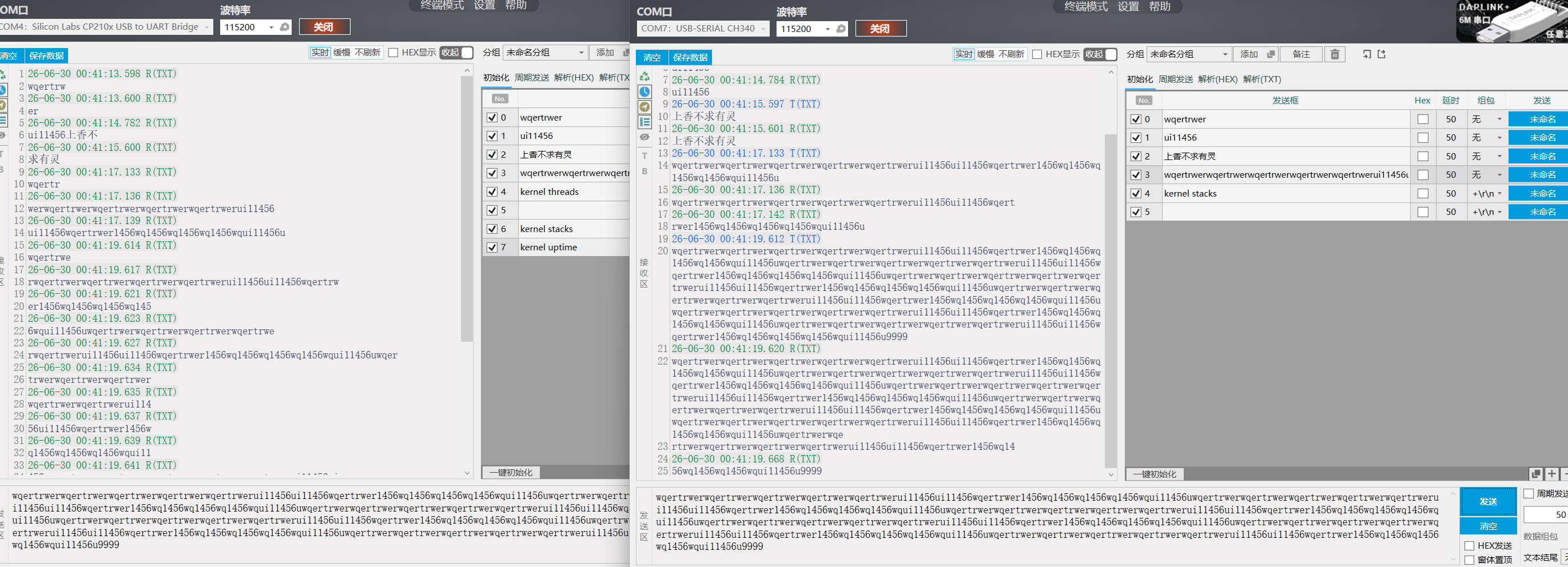
使用中断方式进行收发测试,效果如下:
左边是调试打印输出口,右边是串口2,接收发送中断对数据的接收与发送回环测试。
源代码如下:
c
#include <stdio.h>
#include <zephyr/kernel.h>
#include <zephyr/drivers/gpio.h>
#include <zephyr/sys_clock.h>
#include <zephyr/drivers/uart.h>
#include <stm32h7xx_hal.h>
#include <string.h>
#define MY_UART DT_NODELABEL(usart2)
const struct device *const uart_dev = DEVICE_DT_GET(MY_UART);
#define TX_RING_BUF_SIZE 256
/* 2. 定义发送环形缓冲区 (Ring Buffer) */
static uint8_t __aligned(4) tx_ring_buffer[TX_RING_BUF_SIZE];
static struct ring_buf tx_ringbuf;
/* --- 接收缓冲区相关 --- */
#define RX_BUF_SIZE 64 // 单次从FIFO读出的数据块大小,可根据需要调整
static uint8_t rx_buf[RX_BUF_SIZE]; // 用于临时存储从FIFO读出的数据
K_MSGQ_DEFINE(uart_msgq, sizeof(uint8_t), 512, 4); // 消息队列,用于将每个字节传递给主线程
/* 4. UART 中断服务函数 (在中断上下文中执行) */
static void uart_irq_callback(const struct device *dev, void *user_data)
{
// 更新中断状态,这一步是必须的
uart_irq_update(dev);
if (dev == DEVICE_DT_GET(DT_NODELABEL(usart2))) {
/********** 接收 (RX) 处理 **********/
// 检查接收FIFO中是否有数据
if (uart_irq_rx_ready(dev)) {
uint8_t rx_buf[RX_BUF_SIZE];
int bytes_read;
// 循环读取FIFO中的所有数据
while ((bytes_read = uart_fifo_read(dev, rx_buf, sizeof(rx_buf))) > 0) {
// 将接收到的每个字节放入消息队列,供主线程处理
for (int i = 0; i < bytes_read; i++) {
if (k_msgq_put(&uart_msgq, &rx_buf[i], K_NO_WAIT) != 0) {
// 队列满,可以在这里添加错误处理
printk("UART RX message queue full!\n");
}
}
}
}
/* 检查发送缓冲区是否为空,并且硬件已准备好发送下一个数据 */
if (uart_irq_tx_ready(dev)) {
uint8_t tx_char;
/* 从环形缓冲区中取出一个字节的数据 */
uint32_t ret = ring_buf_get(&tx_ringbuf, &tx_char, 1);
if (ret == 1) {
/* 有数据,通过中断驱动的API发送出去 */
uart_fifo_fill(dev, &tx_char, 1);
} else {
/* 无数据可发,关闭发送中断以节省CPU资源 */
uart_irq_tx_disable(dev);
}
}
}
}
/* 5. 外部函数:将数据放入发送环形缓冲区 */
int uart_send_data(const uint8_t *data, size_t len)
{
if (!device_is_ready(uart_dev)) {
return -ENODEV;
}
/* 将数据放入环形缓冲区 */
uint32_t ret = ring_buf_put(&tx_ringbuf, data, len);
if (ret < len) {
/* 缓冲区空间不足 */
return -ENOMEM;
}
/* 重要:启用发送中断,触发 uart_irq_callback 函数 */
uart_irq_tx_enable(uart_dev);
return 0;
}
/* 6. UART 初始化 */
void uart_interrupt_init(void)
{
if (!device_is_ready(uart_dev)) {
printk("UART device '%s' not ready.\n", uart_dev->name);
//return;
}
/* 初始化环形缓冲区 */
ring_buf_init(&tx_ringbuf, sizeof(tx_ring_buffer), tx_ring_buffer);
/* 注册中断回调函数 */
uart_irq_callback_user_data_set(uart_dev, uart_irq_callback, NULL);
/* 启用接收中断 (可选) */
uart_irq_rx_enable(uart_dev);
/* 注意: 发送中断 (TX) 在初始化时先不开启,在有数据发送请求时再开启 */
}
int main(void)
{
int ret;
uart_interrupt_init();
printk("Interrupt-driven UART TX demo started.\n");
/* 示例:定时发送数据 */
const char *test_msg = "Hello from UART Interrupt Mode!\n";
// 接收消息队列的处理线程
uint8_t received_char;
while (1) {
// 非阻塞地处理消息队列中的字符
if (k_msgq_get(&uart_msgq, &received_char, K_MSEC(100)) == 0)
{
// 将接收到的字符回显出去,并打印到控制台
uart_send_data(&received_char, 1);
printk("%c", received_char);
}
// 每隔2秒发送一次测试消息
/* static uint32_t last_send_time = 0;
uint32_t now = k_uptime_get_32();
if (now - last_send_time >= 2000)
{
uart_send_data((const uint8_t *)test_msg, strlen(test_msg));
last_send_time = now;
} */
}
return 0;
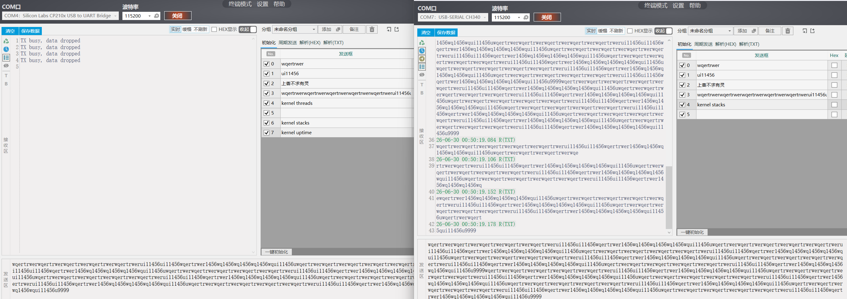
}2、使用dma方式:
效果如下
源代码:
c
/*
 * Copyright (c) 2016 Intel Corporation
 *
 * SPDX-License-Identifier: Apache-2.0
 */

#include <stdio.h>
#include <zephyr/kernel.h>
#include <zephyr/drivers/gpio.h>
#include <zephyr/sys_clock.h>
#include <zephyr/drivers/uart.h>
#include <stm32h7xx_hal.h>
#include <string.h>
#include <stdbool.h>
#include <zephyr/drivers/dma.h>
#include <zephyr/cache.h>

/* 1000 msec = 1 sec */
#define SLEEP_TIME_MS   1000

/* The devicetree node identifier for the "led0" alias. */
#define LED0_NODE DT_ALIAS(led0)
#define MY_GPIO_NODE DT_ALIAS(mygpiog7)
#define UART2_NODE  DT_NODELABEL(usart2)
#define SW0_NODE    DT_ALIAS(mysingpiod9)


// 辅助函数:获取当前 VOS 等级
static uint32_t get_vos_scale(void) {
    // 读取 PWR 控制寄存器 3 的 VOS 位
    return (PWR->D3CR & PWR_D3CR_VOS) >> PWR_D3CR_VOS_Pos;
}
/* 定义接收和发送缓冲区,必须使用 __nocache 解决 D-Cache 一致性问题 */
#define RX_BUF_SIZE 256
static uint8_t __nocache rx_buf0[RX_BUF_SIZE];
static uint8_t __nocache rx_buf1[RX_BUF_SIZE];
static uint8_t __nocache *current_rx_buf = rx_buf0;

/* 发送缓冲区,用于回环发送 */
static uint8_t __nocache tx_buf[RX_BUF_SIZE];

static const struct device *uart2_dev;
static bool tx_pending = false; // 标记是否正在发送
/* UART 异步事件回调 */
static void uart_callback(const struct device *dev, struct uart_event *evt, void *user_data)
{
    switch (evt->type) {
    case UART_RX_RDY:
        {
            /* 接收到的数据位置和长度 */
            uint8_t *data = evt->data.rx.buf + evt->data.rx.offset;
            size_t len = evt->data.rx.len;

            /* 拷贝数据到发送缓冲区 */
            memcpy(tx_buf, data, len);
  if (!tx_pending) {
       // 用 K_NO_WAIT 或 极短超时,不等待,立刻返回
            if (uart_tx(dev, tx_buf, len, 0) == 0) {
                tx_pending = true; // 标记发送开始
            } else {
                printk("TX start failed\n");
            }
        } else {
            // 如果上一次发送还没完,可以选择丢弃新数据或覆盖缓冲区
            // 注意:这里简单丢弃了
            printk("TX busy, data dropped\n");
        }
		}
        break;
 case UART_TX_DONE:
        // DMA 发送真正完成,清除"忙"标志
        tx_pending = false;
        break;
    case UART_RX_BUF_REQUEST:
        /* 提供新的接收缓冲区,实现链式接收 */
        if (current_rx_buf == rx_buf0) {
            uart_rx_buf_rsp(dev, rx_buf1, RX_BUF_SIZE);
            current_rx_buf = rx_buf1;
        } else {
            uart_rx_buf_rsp(dev, rx_buf0, RX_BUF_SIZE);
            current_rx_buf = rx_buf0;
        }
        break;

    case UART_RX_STOPPED:
        printk("UART RX stopped, reason: %d\n", evt->data.rx_stop.reason);
        break;

    default:
        break;
    }
}
int main(void)
{
    int ret;
  // 读取并打印当前 VOS 等级
    uint32_t current_vos = get_vos_scale();
    printk("Current VOS scale: %lu\n", current_vos);
    if (current_vos == 0) {
        printk("VOS0 is active, system is running at high performance.\n");
    } else {
        printk("VOS0 is NOT active. Check PM configuration.\n");
    }
     printk("HW cycles per sec: %u\n", sys_clock_hw_cycles_per_sec());

    /* 1. 获取UART2设备句柄 */
    uart2_dev = DEVICE_DT_GET(UART2_NODE);
    if (!device_is_ready(uart2_dev)) {
        printk("UART2 device not ready!\n");
        return 0;
    }

    /* 2. 注册异步回调函数 */
    ret = uart_callback_set(uart2_dev, uart_callback, NULL);
    if (ret < 0) {
        printk("Failed to set callback: %d\n", ret);
        return 0;
    }

 /* 启动接收,使用第一个缓冲区 */
    ret = uart_rx_enable(uart2_dev, rx_buf0, RX_BUF_SIZE, 50);
    if (ret < 0) {
        printk("RX enable failed: %d\n", ret);
        return 0;
    }
   printk("UART2 echo (DMA RX+TX) ready. Send data to USART2, 'ok' will appear on USART1.\n");

    while (1) {
        k_sleep(K_FOREVER);
    }
	return 0;
}
关于app.overlay
c
&usart2 {
  status = "okay";
    current-speed = <115200>;
    pinctrl-0 = <&usart2_tx_pd5 &usart2_rx_pd6>;
    pinctrl-names = "default";
    // DMA配置部分
    dmas = <&dmamux1 2 44 0x440>,  // TX通道的DMAMUX配置
           <&dmamux1 3 43 0x480>;  // RX通道的DMAMUX配置
    dma-names = "tx", "rx";
};
&dma1 {
    status = "okay";
};
&dmamux1 {
    status = "okay";
};
prj.conf
c
# 启用 UART 和 Console
CONFIG_SERIAL=y
CONFIG_CONSOLE=y
CONFIG_UART_CONSOLE=y

# 启用 Shell
CONFIG_SHELL=y
# [关键] 解决可能的 cache 一致性问题的关键选项
CONFIG_UART_ASYNC_API=y
CONFIG_DMA=y                  # 显式启用 DMA 支持
CONFIG_DMA_STM32=y
CONFIG_NOCACHE_MEMORY=y       # 保持 DMA 缓冲区一致性

# 启用接收中断
CONFIG_UART_INTERRUPT_DRIVEN=y