一、实验拓扑
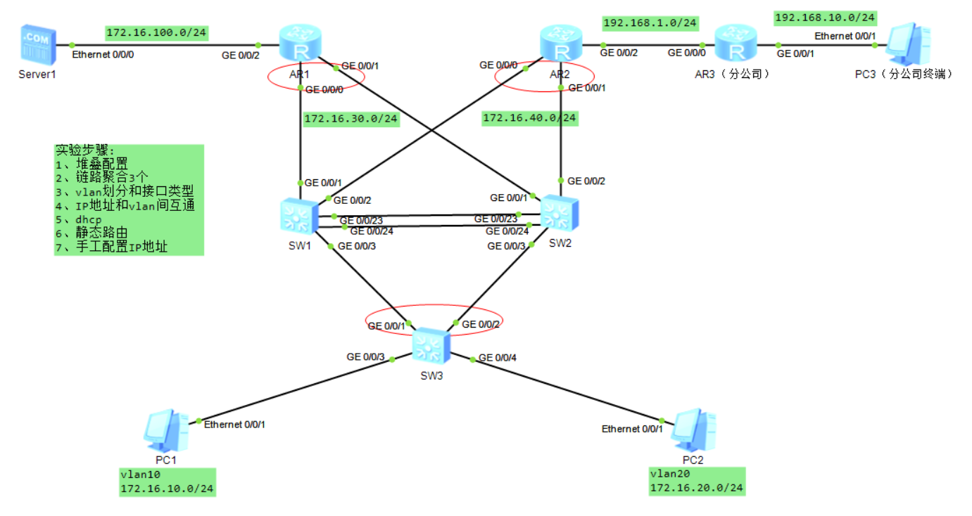
设备说明
表格
| 设备名称 | 角色 | 说明 |
|---|---|---|
| SW1、SW2 | 汇聚交换机 | 堆叠,3 组 Eth‑Trunk 链路聚合,三层 VLANIF 网关 |
| SW3 | 接入交换机 | 接入 PC1、PC2 终端 |
| AR1 | 总部路由器 | 连接 Server1,双链路接入堆叠 SW1/SW2 |
| AR2 | 总部路由器 | 双链路接入堆叠 SW1/SW2,连接分公司 AR3 |
| AR3 | 分公司路由器 | 分公司网关,连接 PC3 分公司终端 |
| Server1 | 服务器 | 172.16.100.0/24 网段 |
| PC1 | 总部终端 | VLAN10,172.16.10.0/24 |
| PC2 | 总部终端 | VLAN20,172.16.20.0/24 |
| PC3 | 分公司终端 | 192.168.10.0/24 |
二、IP & 接口规划
表格
| 网段 | 网段地址 | 网关 | 互联接口 |
|---|---|---|---|
| 服务器网段 | 172.16.100.0/24 | 172.16.100.254 | AR1 GE0/0/2 ↔ Server1 Eth0/0/0 |
| AR1‑堆叠 SW1/SW2 | 172.16.30.0/24 | ‑ | AR1 GE0/0/0→SW1 GE0/0/1; AR1 GE0/0/1→SW2 GE0/0/2 |
| AR2‑堆叠 SW1/SW2 | 172.16.40.0/24 | ‑ | AR2 GE0/0/0→SW1 GE0/0/2; AR2 GE0/0/1→SW2 GE0/0/1 |
| 总部 VLAN10 | 172.16.10.0/24 | 172.16.10.254 | SW3 GE0/0/3 接 PC1 (Eth0/0/1) |
| 总部 VLAN20 | 172.16.20.0/24 | 172.16.20.254 | SW3 GE0/0/4 接 PC2 (Eth0/0/1) |
| AR2‑AR3 互联网段 | 192.168.1.0/24 | ‑ | AR2 GE0/0/2 ↔ AR3 GE0/0/0 |
| 分公司业务网段 | 192.168.10.0/24 | 192.168.10.254 | AR3 GE0/0/1 ↔ PC3 Eth0/0/1 |
堆叠链路:SW1 XGE0/0/23、XGE0/0/24 <--> SW2 XGE0/0/23、XGE0/0/24 链路聚合:SW1 GE0/0/3 、SW2 GE0/0/3 上联接入 SW3 GE0/0/1、GE0/0/2
实验需求
- SW1、SW2 做堆叠,设备冗余
- 3 组 Eth‑Trunk 链路聚合
- VLAN 划分,Access/Trunk 接口配置,VLANIF 实现 VLAN 间互通
- DHCP 全局地址池,PC1、PC2 自动获取 IP
- 静态路由实现:Server1、PC1、PC2、PC3 全网互通
- Server1、PC3 手工静态 IP
三、设备完整配置脚本
⚠️堆叠配置完成,
save保存,reboot重启交换机,堆叠生效后再配置业务。
SW1(堆叠主)
sysname SW1
#堆叠配置
stack priority 150
stack member 1 domain 1
interface XGigabitEthernet0/0/23
 stack mode stack
interface XGigabitEthernet0/0/24
 stack mode stack
save
reboot

#堆叠生效后业务配置
#聚合1:SW1 <-> SW2业务Eth‑Trunk1
interface Eth‑Trunk 1
 mode lacp‑static
 port link‑type trunk
 port trunk permit vlan all
interface GigabitEthernet1/0/2
 eth‑trunk 1

#聚合2:SW1、SW2上联SW3 Eth‑Trunk3
interface Eth‑Trunk 3
 mode lacp‑static
 port link‑type trunk
 port trunk permit vlan 10 20
interface GigabitEthernet1/0/3
 eth‑trunk 3

#创建VLAN
vlan batch 10 20 30 40 100

#对接AR1接口
interface GigabitEthernet1/0/1
 port link‑type access
 port default vlan 30
interface Vlanif30
 ip address 172.16.30.2 255.255.255.0

#对接AR2接口
interface GigabitEthernet1/0/2
 port link‑type access
 port default vlan 40
interface Vlanif40
 ip address 172.16.40.2 255.255.255.0

#VLANIF三层网关
interface Vlanif10
 ip address 172.16.10.254 255.255.255.0
 dhcp select global
interface Vlanif20
 ip address 172.16.20.254 255.255.255.0
 dhcp select global
interface Vlanif100
 ip address 172.16.100.254 255.255.255.0

#DHCP全局配置
dhcp enable
ip pool vlan10
 network 172.16.10.0 mask 255.255.255.0
 gateway‑list 172.16.10.254
 dns‑list 223.5.5.5
ip pool vlan20
 network 172.16.20.0 mask 255.255.255.0
 gateway‑list 172.16.20.254
 dns‑list 223.5.5.5

#静态路由,去往服务器、分公司网段
ip route‑static 172.16.100.0 255.255.255.0 172.16.30.1
ip route‑static 192.168.1.0 255.255.255.0 172.16.40.1
ip route‑static 192.168.10.0 255.255.255.0 172.16.40.1
SW2(堆叠备)
sysname SW2
stack member 2 domain 1
interface XGigabitEthernet0/0/23
 stack mode stack
interface XGigabitEthernet0/0/24
 stack mode stack
save
reboot

#业务配置
interface Eth‑Trunk 1
 mode lacp‑static
 port link‑type trunk
 port trunk permit vlan all
interface GigabitEthernet2/0/1
 eth‑trunk 1

interface Eth‑Trunk 3
 mode lacp‑static
 port link‑type trunk
 port trunk permit vlan 10 20
interface GigabitEthernet2/0/3
 eth‑trunk 3

#对接AR1
interface GigabitEthernet2/0/2
 port link‑type access
 port default vlan 30
#对接AR2
interface GigabitEthernet2/0/1
 port link‑type access
 port default vlan 40
SW3 接入交换机
sysname SW3
vlan batch 10 20

#上联堆叠SW1 SW2 Eth‑Trunk3
interface Eth‑Trunk 3
 mode lacp‑static
 port link‑type trunk
 port trunk permit vlan 10 20
interface GigabitEthernet0/0/1
 eth‑trunk 3
interface GigabitEthernet0/0/2
 eth‑trunk 3

#PC接入接口
interface GigabitEthernet0/0/3
 port link‑type access
 port default vlan 10
interface GigabitEthernet0/0/4
 port link‑type access
 port default vlan 20
AR1 路由器
sysname AR1
interface GigabitEthernet0/0/2
 ip address 172.16.100.1 255.255.255.0
interface GigabitEthernet0/0/0
 ip address 172.16.30.1 255.255.255.0
interface GigabitEthernet0/0/1
 ip address 172.16.30.1 255.255.255.0

#静态回指总部、分公司路由
ip route‑static 172.16.10.0 255.255.255.0 172.16.30.2
ip route‑static 172.16.20.0 255.255.255.0 172.16.30.2
ip route‑static 172.16.40.0 255.255.255.0 172.16.30.2
ip route‑static 192.168.1.0 255.255.255.0 172.16.30.2
ip route‑static 192.168.10.0 255.255.255.0 172.16.30.2
AR2 路由器
sysname AR2
interface GigabitEthernet0/0/0
 ip address 172.16.40.1 255.255.255.0
interface GigabitEthernet0/0/1
 ip address 172.16.40.1 255.255.255.0
interface GigabitEthernet0/0/2
 ip address 192.168.1.1 255.255.255.0

#静态路由
ip route‑static 172.16.10.0 255.255.255.0 172.16.40.2
ip route‑static 172.16.20.0 255.255.255.0 172.16.40.2
ip route‑static 172.16.100.0 255.255.255.0 172.16.40.2
ip route‑static 192.168.10.0 255.255.255.0 192.168.1.2
AR3 分公司路由器
sysname AR3
interface GigabitEthernet0/0/0
 ip address 192.168.1.2 255.255.255.0
interface GigabitEthernet0/0/1
 ip address 192.168.10.254 255.255.255.0

#回指全部总部网段
ip route‑static 172.16.0.0 255.255.0.0 192.168.1.1
四、终端配置
表格
| 终端 | IP 地址 | 网关 | 获取方式 |
|---|---|---|---|
| Server1 | 172.16.100.10/24 | 172.16.100.254 | 静态 IP |
| PC1(VLAN10) | 自动获取 | 172.16.10.254 | DHCP |
| PC2(VLAN20) | 自动获取 | 172.16.20.254 | DHCP |
| PC3 (分公司) | 192.168.10.10/24 | 192.168.10.254 | 静态 IP |
五、验证命令
display stack
display eth‑trunk
display ip interface brief
display ip routing‑table
display ip pool
连通测试
- PC1 ping PC2:VLAN10 与 VLAN20 三层互通
- PC1 ping Server1:办公访问总部服务器
- PC1 ping PC3:总部访问分公司终端
- PC3 ping Server1:分公司访问总部服务器
六、排错要点
- 堆叠 :堆叠口
stack mode stack,配置完必须保存重启。 - AR1、AR2 双链路接堆叠 :两台路由器两个物理接口配置相同 IP,eNSP 模拟双上行;
- Eth‑Trunk:两端 lacp‑static 模式一致,物理接口不要配置业务,加入聚合组;
- DHCP :全局
dhcp enable,VLANIF 接口dhcp select global; - 路由单向不通:AR1、AR2、AR3、SW1/SW2 全部需要双向静态路由。
七、实验总结
本实验模拟企业双路由器上行 + 堆叠汇聚架构,SW1/SW2 堆叠实现设备冗余,Eth‑Trunk 链路聚合提升带宽可靠性;VLAN 隔离业务,VLANIF 实现 VLAN 三层互通,DHCP 自动分配终端地址,静态路由完成总部服务器、办公、分公司全网互通。完整覆盖 HCIA 综合实验全部考点。