准备工作:
-
软件:keil5
-
硬件:STM32F407ZET6芯片,gec6818开发板,st-link调试器
-
文档:《开发板原理图》,《Cortex M3与M4权威指南》,《STM32F407参考手册_英文》
-
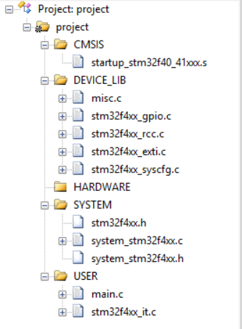
项目结构:
相关电路图:
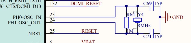
- 开发板外部时钟8MHz,电路(来自《开发板原理图》):
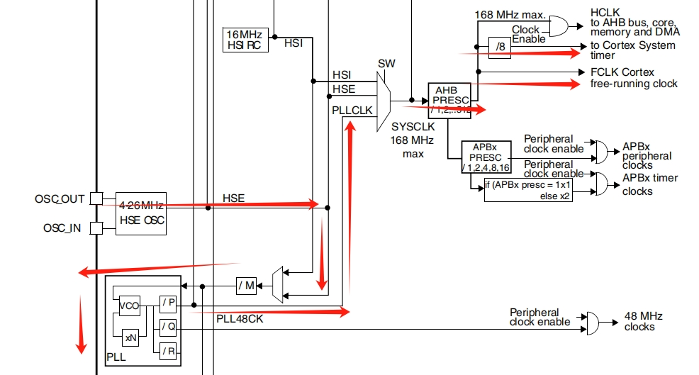
- 内核时钟电路图(来自《STM32F407参考手册_英文》5.2章):
一、systick定时器使用逻辑
根据《Cortex M3与M4权威指南》第8章:
内核有四个寄存器用于控制和使用定时器:
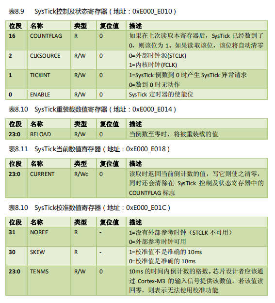
- 控制与状态寄存器 用于选择时钟 、查看计数器是否数到了0 、时钟使能
- 重载数值寄存器用于装载计数次数
- 当前数值寄存器用于读取当前值,写入任意值会使之清零
- 校准数值寄存器本篇没有使用
英文版权威指南直接给出了参考代码:
SysTick->CTRL = 0; // Disable SysTick
SysTick->LOAD = 0xFF; // Count from 255 to 0 (256 cycles)
SysTick->VAL = 0; // Clear current value as well as count fla
SysTick->CTRL = 5; // Enable SysTick timer with processor clock
while ((SysTick->CTRL & 0x00010000)==0);// Wait until count flag is set
SysTick->CTRL = 0; // Disable SysTick
计数、重载、使能、计数是否到头这些操作都很好理解,重要的是STCLK、FCLK两个时钟源的频率到底是多少,否则就无法知道到底计数了多长时间。
通过内核时钟原理图可以知道,STCLK、FCLK两个时钟源挂载于AHB1总线上,而总线时钟是由HSE外部时钟经过PLL(倍频锁相环)放大得到,使用PLL的M、N、P、Q等参数。
根据电路图我们可以计算得到AHB1总线频率的公式是:
HSE_VALUE / PLL_M * PLL_N / PLL_P
参数在代码中的定义如下:
c
-- system_stm32f4xx.c 文件--

/************************* PLL Parameters *************************************/
#if defined (STM32F40_41xxx) || defined (STM32F427_437xx) || defined (STM32F429_439xx) || defined (STM32F401xx)
/* PLL_VCO = (HSE_VALUE or HSI_VALUE / PLL_M) * PLL_N */
#define **PLL_M**      8        // 库文件默认25
#else /* STM32F411xE */
#if defined (USE_HSE_BYPASS)
#define PLL_M      8
#else /* STM32F411xE */
#define PLL_M      16
#endif /* USE_HSE_BYPASS */
#endif /* STM32F40_41xxx || STM32F427_437xx || STM32F429_439xx || STM32F401xx */

/* USB OTG FS, SDIO and RNG Clock =  PLL_VCO / PLLQ */
#define PLL_Q      7

#if defined (STM32F40_41xxx)
#define PLL_N      336
/* SYSCLK = PLL_VCO / PLL_P */
#define PLL_P      2
#endif /* STM32F40_41xxx */

/******************************************************************************/
外部时钟频率定义如下:
c
-- stm32f4xx.h文件 --

/**

 * @brief In the following line adjust the value of External High Speed oscillator (HSE)
   used in your application

   Tip: To avoid modifying this file each time you need to use different HSE, you
        can define the HSE value in your toolchain compiler preprocessor.
     */

#if !defined  (HSE_VALUE)

 // 库文件默认25000000

  #define HSE_VALUE    ((uint32_t)8000000) /*!< Value of the External oscillator in Hz */

#endif /* HSE_VALUE */
所以AHB1总线的频率为:
8MHz / 8 * 336 / 2 = 168MHz
也就是芯片标注的可以达到的最大频率。因此:
- FCLK频率:168MHz
- STCLK频率:168MHz / 8 = 21MHz
而频率越低,说明单次计时时间更长,在寄存器计数次数有限的情况下,总时长更长,所以我们选择STCLK作为时钟源。
所以接下来代码就水到渠成了。
二、完整代码
c
/********************************************************************************
* @file    GPIO/GPIO_IOToggle/main.c
* @author  MCD Application Team
* @version V1.4.0
* @date    2025/4/25
* @brief   按键中断点亮led后延时熄灭
******************************************************************************/

#include "stm32f4xx.h"

// KEY引脚初始化
void KEY_Init()
{
	GPIO_InitTypeDef  GPIO_InitStructure;

	/* 打开外设时钟 */
	RCC_AHB1PeriphClockCmd(RCC_AHB1Periph_GPIOA, ENABLE);

	/* 初始化PA0 */
	GPIO_InitStructure.GPIO_Pin = GPIO_Pin_0;
	GPIO_InitStructure.GPIO_Mode = GPIO_Mode_IN;
	GPIO_InitStructure.GPIO_PuPd = GPIO_PuPd_NOPULL;
	GPIO_Init(GPIOA, &GPIO_InitStructure);
}


// LED引脚初始化
void LED_Init()
{
	GPIO_InitTypeDef  GPIO_InitStructure;

	/* 打开外设时钟 */
	RCC_AHB1PeriphClockCmd(RCC_AHB1Periph_GPIOF, ENABLE);

	/* 初始化PF9 */
	GPIO_InitStructure.GPIO_Pin =  GPIO_Pin_9;
	GPIO_InitStructure.GPIO_Mode = GPIO_Mode_OUT;
	GPIO_InitStructure.GPIO_OType = GPIO_OType_PP;
	GPIO_InitStructure.GPIO_Speed = GPIO_Speed_100MHz;
	GPIO_InitStructure.GPIO_PuPd = GPIO_PuPd_NOPULL;
	GPIO_Init(GPIOF, &GPIO_InitStructure);
}

// 配置中断
static void EXTILine0_Config(void)
{
	EXTI_InitTypeDef   EXTI_InitStructure;
	NVIC_InitTypeDef   NVIC_InitStructure;

	// 打开GPIOA、SYSCFG外设时钟
	RCC_AHB1PeriphClockCmd(RCC_AHB1Periph_GPIOA, ENABLE);
	RCC_APB2PeriphClockCmd(RCC_APB2Periph_SYSCFG, ENABLE);

	/* Connect EXTI Line0 to PA0 pin
		EXTI_PortSourceGPIOx : selects the GPIO port
		EXTI_PinSourcex: specifies the EXTI line to be configured.
	*/
	SYSCFG_EXTILineConfig(EXTI_PortSourceGPIOA, EXTI_PinSource0);

	/* Configure EXTI Line0 ,配置中断线路、中断模式、上升沿、使能*/
	EXTI_InitStructure.EXTI_Line = EXTI_Line0;
	EXTI_InitStructure.EXTI_Mode = EXTI_Mode_Interrupt;
	EXTI_InitStructure.EXTI_Trigger = EXTI_Trigger_Falling;
	EXTI_InitStructure.EXTI_LineCmd = ENABLE;
	EXTI_Init(&EXTI_InitStructure);

	/* Enable and set EXTI Line0 Interrupt to the lowest priority,NVIC在内核中负责调度 */
	NVIC_InitStructure.NVIC_IRQChannel = EXTI0_IRQn;
	NVIC_InitStructure.NVIC_IRQChannelPreemptionPriority = 0x0F;
	NVIC_InitStructure.NVIC_IRQChannelSubPriority = 0x0F;
	NVIC_InitStructure.NVIC_IRQChannelCmd = ENABLE;
	NVIC_Init(&NVIC_InitStructure);
}


// 选择外部时钟源STCLK作为计时时钟源,来自于HSE
// 源头来自外部时钟8MHz,经过PLL倍频锁相环放大后得到ABH1总线的168MHZ,然后再/8,得到21MHz(STCLK)
// 或者也可以直接使用168MHz(FCLK),但是在寄存器位数固定的情况下,21MHz可以计数的时长更长,所以选择21MHz
// 21MHz,1/21us计数一次,24位倒数寄存器的最大计数次数为2^24, 换算成us,为798915us
// 延时微秒
void delay_us(unsigned int n)
{
	SysTick->CTRL = 0; // Disable SysTick
	SysTick->LOAD = n * 21 - 1; // Count from 255 to 0 (256 cycles),0算一次,所以要减1
	SysTick->VAL = 0; // Clear current value as well as count fla

	// 0位控制使能,2位控制选择FCLK(1)还是STCLK(1),这里选择stclk
	SysTick->CTRL = 1; // Enable SysTick timer with processor clock

	while ((SysTick->CTRL & 0x00010000)==0);// Wait until count flag is set,控制寄存器的第16位用于检测是否计数结束
	SysTick->CTRL = 0; // Disable SysTick
}


// 21MHz,1/21us计数一次,24位倒数寄存器的最大计数次数为2^24, 换算成ms,为798ms
// 延时毫秒
void delay_ms(unsigned int n)
{
	SysTick->CTRL = 0; // Disable SysTick
	SysTick->LOAD = n * 21 * 1000 - 1; // Count from 255 to 0 (256 cycles),0算一次,所以要减1
	SysTick->VAL = 0; // Clear current value as well as count fla

	// 0位控制使能,2位控制选择FCLK(1)还是STCLK(1),这里选择stclk
	SysTick->CTRL = 1; // Enable SysTick timer with processor clock

	while ((SysTick->CTRL & 0x00010000)==0);// Wait until count flag is set,控制寄存器的第16位用于检测是否计数结束
	SysTick->CTRL = 0; // Disable SysTick
}

// 延时秒
void delay_s(unsigned int n)
{
	while(n--)
	{
		delay_ms(500);
		delay_ms(500);
	}
}

// 非精确延时函数
void delay(int n)
{
	while(n--);
}

// 线路0中断处理函数
void EXTI0_IRQHandler(void)
{
    // led引脚置位
	GPIO_ResetBits(GPIOF, GPIO_Pin_9);
    // 延时2s
	delay_s(2);
    // 清除中断挂起状态
	EXTI_ClearITPendingBit(EXTI_Line0);
}

int main()
{
	// 初始化按键
	KEY_Init();
	// 初始化LED灯
	LED_Init();
	// 初始化NVIC外设
	EXTILine0_Config();
	while(1)
	{
        // LED默认熄灭
		GPIO_SetBits(GPIOF, LED0_PIN);
	}
}
三、总结
延时函数代码本身其实并不是很难编写,只有短短几行代码,而且官方也有很清楚的示例代码,寄存器的对象也做了完整的封装,难就难在理解stm32内核时钟的组成和由来,从而通过手动调整参数满足自己的要求。