一、实验
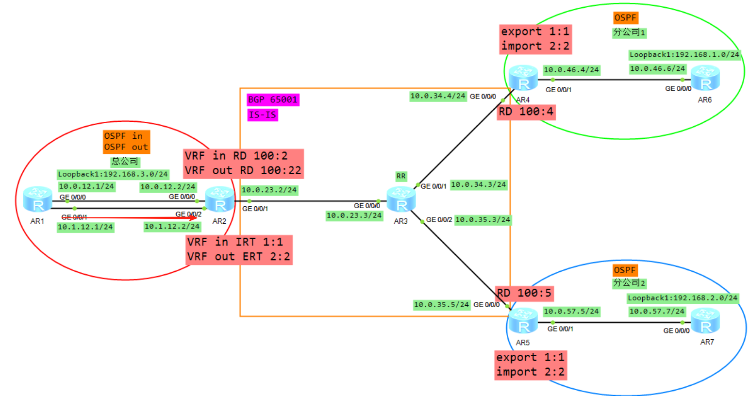
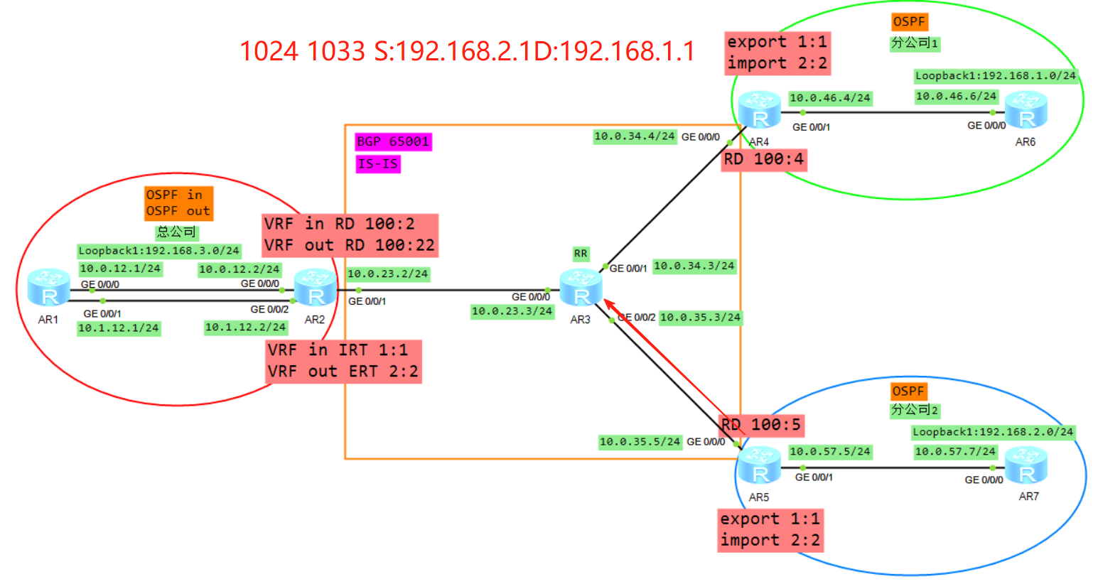
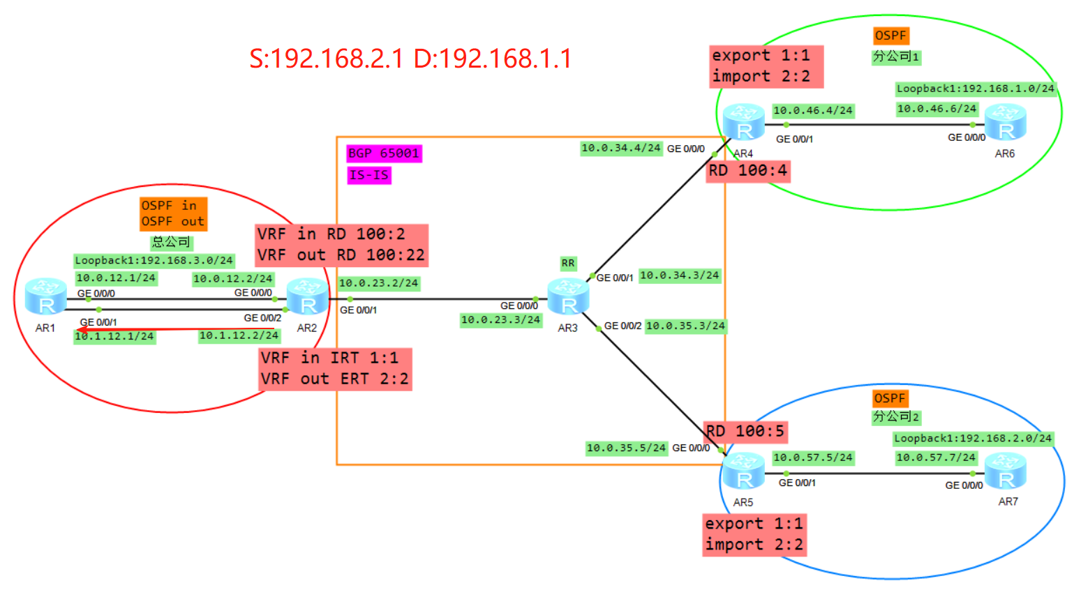
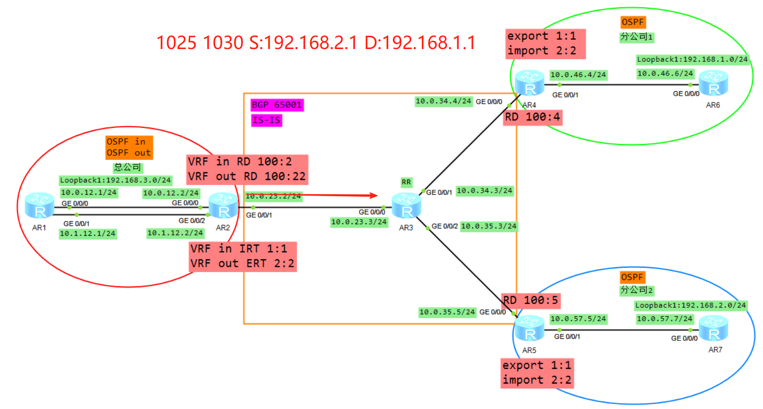
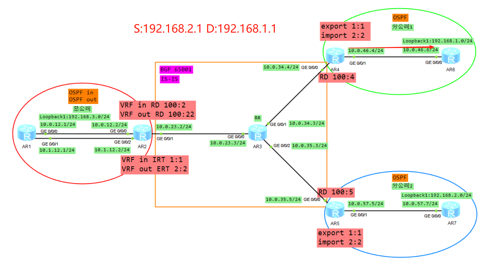
拓扑
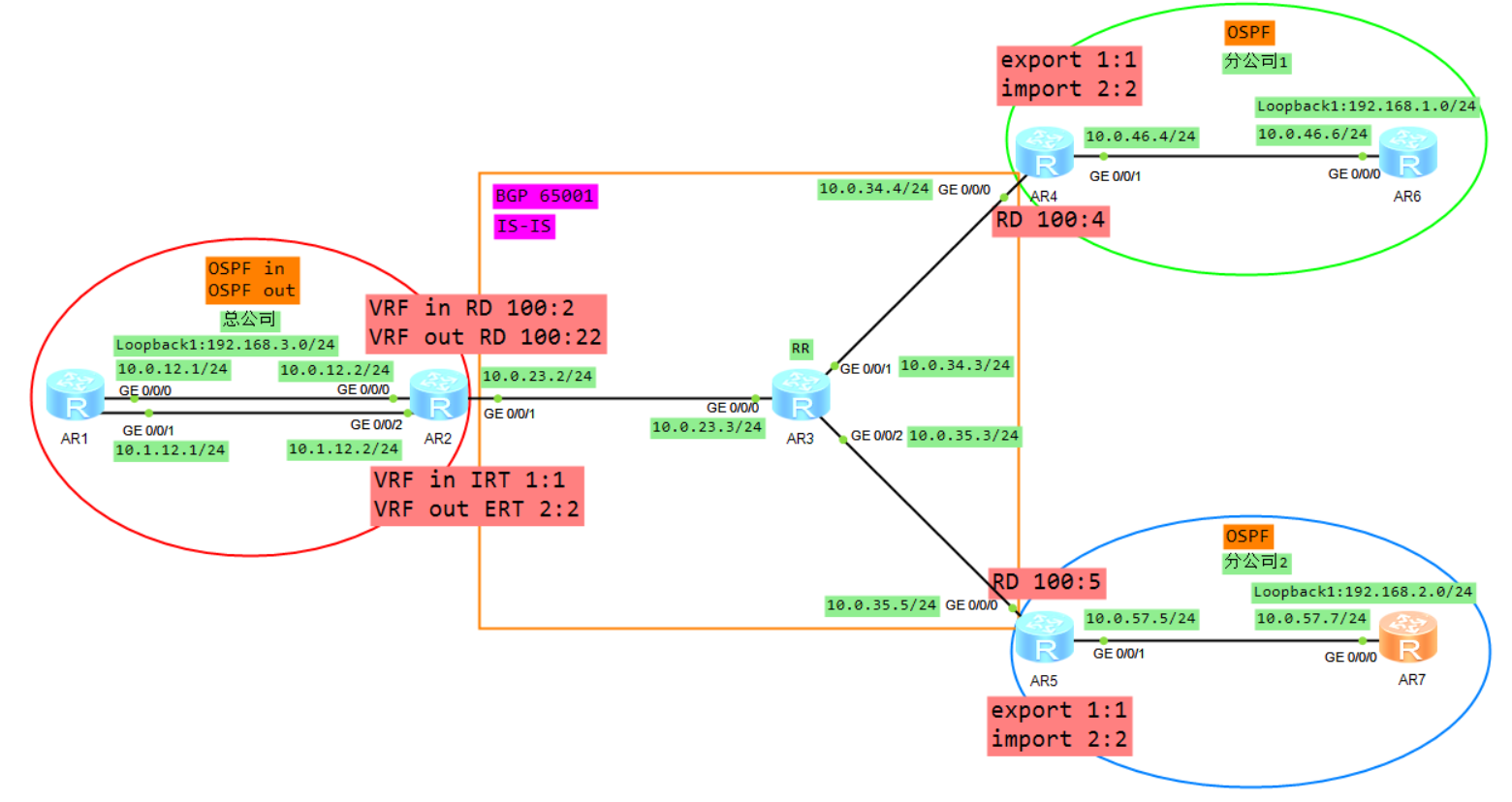
1、基础配置
AR1
system
sysname AR1
int g 0/0/0
ip add 10.0.12.1 24
int g 0/0/1
ip add 10.1.12.1 24
int l 0
ip add 1.1.1.1 32
int l 1
ip add 192.168.3.1 24

AR2
system
sysname AR2
ip vpn-instance in
ipv4-family
q
q
ip vpn-instance out
 ipv4-family
q
q
int g 0/0/0
ip binding vpn-instance in
ip add 10.0.12.2 24
int g 0/0/2
ip binding vpn-instance out
ip add 10.1.12.2 24
int g 0/0/1
ip add 10.0.23.2 24
int l 0
ip add 2.2.2.2 32

AR3
system
sysname AR3
int g 0/0/0
ip add 10.0.23.3 24
int g 0/0/1
ip add 10.0.34.3 24
int g 0/0/2
ip add 10.0.35.3 24
int l 0
ip add 3.3.3.3 32

AR4
system
sysname AR4
ip vpn-instance A
ipv4-family
q
q
int g 0/0/0
ip add 10.0.34.4 24
int g 0/0/1
ip binding vpn-instance A
ip add 10.0.46.4 24
int l 0
ip add 4.4.4.4 32

AR5
system
sysname AR5
ip vpn-instance B
ipv4-family
q
q
int g 0/0/0
ip add 10.0.35.5 24
int g 0/0/1
ip binding vpn-instance B
ip add 10.0.57.5 24
int l 0
ip add 5.5.5.5 32

AR6
system
sysname AR6
int g 0/0/0
ip add 10.0.46.6 24
int l 0
ip add 6.6.6.6 32
int l 1
ip add 192.168.1.1 24

AR7
system
sysname AR7
int g 0/0/0
ip add 10.0.57.7 24
int l 0
ip add 7.7.7.7 32
int l 1
ip add 192.168.2.1 24
查看实例
[AR2]display ip vpn-instance
 Total VPN-Instances configured      : 2
 Total IPv4 VPN-Instances configured : 2
 Total IPv6 VPN-Instances configured : 0

  VPN-Instance Name               RD                    Address-family
  in                                                    IPv4
  out                                                   IPv4

[AR4]display ip vpn-instance
 Total VPN-Instances configured      : 1
 Total IPv4 VPN-Instances configured : 1
 Total IPv6 VPN-Instances configured : 0

  VPN-Instance Name               RD                    Address-family
  A                                                     IPv4

[AR5]display ip vpn-instance
 Total VPN-Instances configured      : 1
 Total IPv4 VPN-Instances configured : 1
 Total IPv6 VPN-Instances configured : 0

  VPN-Instance Name               RD                    Address-family
  B                                                     IPv4
2、公司内部IGP路由配置
AR1
ospf 1 router-id 1.1.1.1
area 0
netw 10.0.12.1 0.0.0.0
netw 10.1.12.1 0.0.0.0
netw 192.168.3.1 0.0.0.255

AR2
ospf 1 vpn-instance in router-id 2.2.2.1
area 0
netw 10.0.12.2 0.0.0.0
q
import-route bgp
q
ospf 2 vpn-instance out router-id 2.2.2.2
area 0
netw 10.1.12.2 0.0.0.0

AR4
ospf 1 router-id 4.4.4.4 vpn-instance A
area 0
netw 10.0.46.4 0.0.0.0

AR5
ospf 1 router-id 5.5.5.5 vpn-instance B
area 0
netw 10.0.57.5 0.0.0.0

AR6
ospf 1 router-id 6.6.6.6
area 0
netw 10.0.46.6 0.0.0.0
netw 192.168.1.0 0.0.0.255

AR7
ospf 1 router-id 7.7.7.7
area 0
netw 10.0.57.7 0.0.0.0
netw 192.168.2.0 0.0.0.255
查看OSPF邻居状态
[AR2]display ospf peer brief

	 OSPF Process 1 with Router ID 2.2.2.1
		  Peer Statistic Information
 ----------------------------------------------------------------------------
 Area Id          Interface                        Neighbor id      State
 0.0.0.0          GigabitEthernet0/0/0             1.1.1.1          Full
 ----------------------------------------------------------------------------

	 OSPF Process 2 with Router ID 2.2.2.2
		  Peer Statistic Information
 ----------------------------------------------------------------------------
 Area Id          Interface                        Neighbor id      State
 0.0.0.0          GigabitEthernet0/0/2             1.1.1.1          Full
 ----------------------------------------------------------------------------

[AR4-ospf-1]display ospf peer brief

	 OSPF Process 1 with Router ID 4.4.4.4
		  Peer Statistic Information
 ----------------------------------------------------------------------------
 Area Id          Interface                        Neighbor id      State
 0.0.0.0          GigabitEthernet0/0/1             6.6.6.6          Full
 ----------------------------------------------------------------------------

[AR5-ospf-1]display ospf peer brief

	 OSPF Process 1 with Router ID 5.5.5.5
		  Peer Statistic Information
 ----------------------------------------------------------------------------
 Area Id          Interface                        Neighbor id      State
 0.0.0.0          GigabitEthernet0/0/1             7.7.7.7          Full
 ----------------------------------------------------------------------------
3、运营商IGP路由配置
AR2
isis 1
network-entity 49.0001.0000.0002.00
q
int g 0/0/1
isis enable
isis circuit-level level-2
int loopback 0
isis enable
isis circuit-level level-2

AR3
isis 1
network-entity 49.0001.0000.0003.00
q
int g 0/0/0
isis enable
isis circuit-level level-2
int g 0/0/1
isis enable
isis circuit-level level-2
int g 0/0/2
isis enable
isis circuit-level level-2
int loopback 0
isis enable
isis circuit-level level-2

AR4
isis 1
network-entity 49.0001.0000.0004.00
q
int g 0/0/0
isis enable
isis circuit-level level-2
int loopback 0
isis enable
isis circuit-level level-2

AR5
isis 1
network-entity 49.0001.0000.0005.00
q
int g 0/0/0
isis enable
isis circuit-level level-2
int loopback 0
isis enable
isis circuit-level level-2
查看IS-IS邻居状态
[AR3]display isis peer

                          Peer information for ISIS(1)

  System Id     Interface          Circuit Id       State HoldTime Type     PRI
-------------------------------------------------------------------------------
0001.0000.0002  GE0/0/0            0001.0000.0002.01 Up   7s       L2       64
0001.0000.0004  GE0/0/1            0001.0000.0004.01 Up   8s       L2       64
0001.0000.0005  GE0/0/2            0001.0000.0003.03 Up   20s      L2       64

Total Peer(s): 3
4、运营商BGP路由配置
AR2
bgp 65001
router-id 2.2.2.2
peer 3.3.3.3 as 65001
peer 3.3.3.3 con l 0
undo peer 3.3.3.3 enable

AR3
bgp 65001
router-id 3.3.3.3
peer 2.2.2.2 as 65001
peer 2.2.2.2 con l 0
peer 4.4.4.4 as 65001
peer 4.4.4.4 con l 0
peer 5.5.5.5 as 65001
peer 5.5.5.5 con l 0
undo peer 2.2.2.2 enable
undo peer 4.4.4.4 enable
undo peer 5.5.5.5 enable

AR4
bgp 65001
router-id 4.4.4.4
peer 3.3.3.3 as 65001
peer 3.3.3.3 con l 0
undo peer 3.3.3.3 enable

AR5
bgp 65001
router-id 5.5.5.5
peer 3.3.3.3 as 65001
peer 3.3.3.3 con l 0
undo peer 3.3.3.3 enable
5、MPLS/LDP配置
AR2
mpls lsr-id 2.2.2.2
mpls
q
mpls ldp
q
int g 0/0/1
mpls
mpls ldp

AR3
mpls lsr-id 3.3.3.3
mpls
q
mpls ldp
q
int g 0/0/0
mpls
mpls ldp
int g 0/0/1
mpls
mpls ldp
int g 0/0/2
mpls
mpls ldp

AR4
mpls lsr-id 4.4.4.4
mpls
q
mpls ldp
q
int g 0/0/0
mpls
mpls ldp

AR5
mpls lsr-id 5.5.5.5
mpls
q
mpls ldp
q
int g 0/0/0
mpls
mpls ldp
查看MPLS lSP
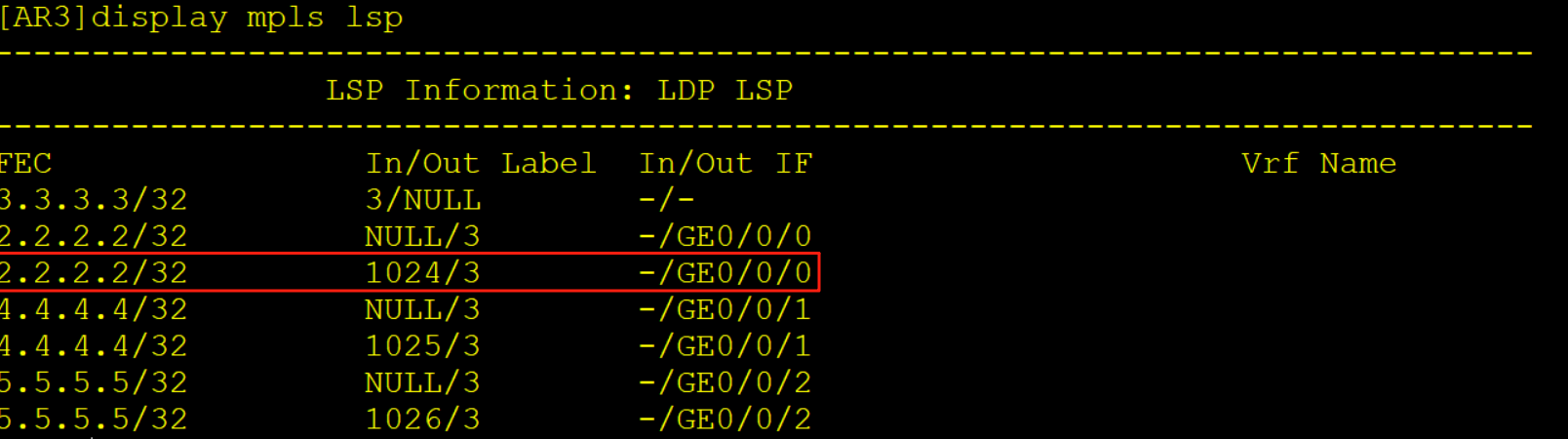
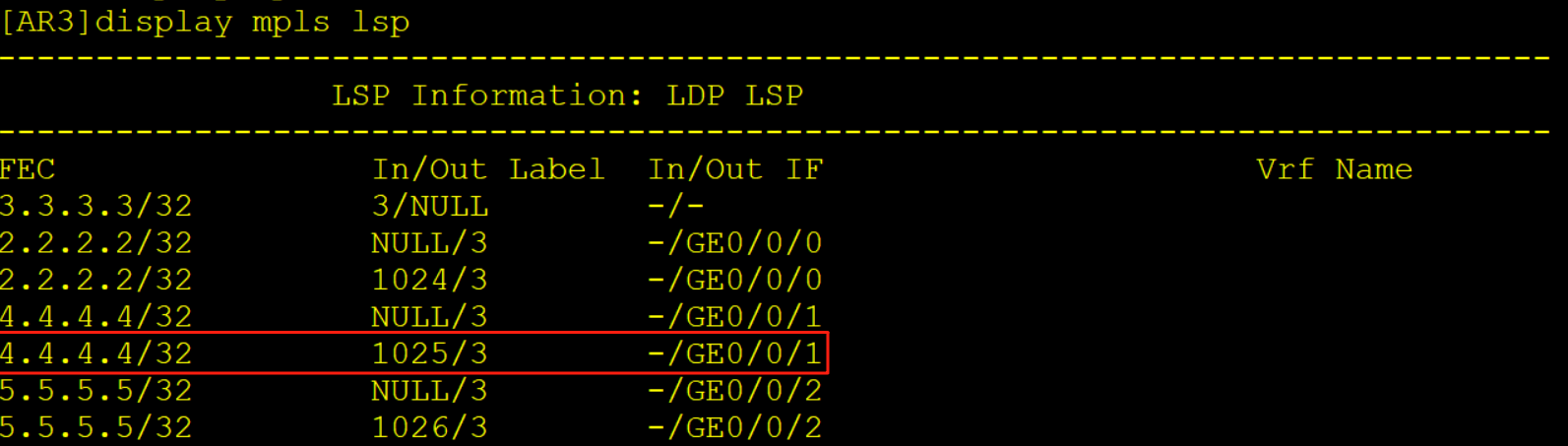
[AR3]display mpls lsp
-------------------------------------------------------------------------------
                 LSP Information: LDP LSP
-------------------------------------------------------------------------------
FEC                In/Out Label  In/Out IF                      Vrf Name
3.3.3.3/32         3/NULL        -/-
2.2.2.2/32         NULL/3        -/GE0/0/0
2.2.2.2/32         1024/3        -/GE0/0/0
4.4.4.4/32         NULL/3        -/GE0/0/1
4.4.4.4/32         1025/3        -/GE0/0/1
5.5.5.5/32         NULL/3        -/GE0/0/2
5.5.5.5/32         1026/3        -/GE0/0/2
6、MP-BGP配置
AR2
ip vpn-instance in
route-distinguisher 100:2
vpn-target 1:1 import-extcommunity
q
ip vpn-instance out
route-distinguisher 100:22
vpn-target 2:2 export-extcommunity
q
bgp 65001
ipv4-family vpnv4
peer 3.3.3.3 enable
q
ipv4-family vpn-instance out
import-route ospf 2
q
q
ospf 1
import-route bgp

AR3
bgp 65001
ipv4-family vpnv4
undo policy vpn-target
peer 2.2.2.2 enable
peer 2.2.2.2 reflect-client
peer 4.4.4.4 enable
peer 4.4.4.4 reflect-client
peer 5.5.5.5 enable
peer 5.5.5.5 reflect-client


AR4
ip vpn-instance A
route-distinguisher 100:4
vpn-target 1:1 export-extcommunity
vpn-target 2:2 import-extcommunity
q
bgp 65001
ipv4-family vpn-instance A
import-route ospf 1
ipv4-family vpnv4
peer 3.3.3.3 enable
q
q
ospf 1
import bgp

AR5
ip vpn-instance B
route-distinguisher 100:5
vpn-target 1:1 export-extcommunity
vpn-target 2:2 import-extcommunity
bgp 65001
ipv4-family vpn-instance B
import-route ospf 1
ipv4-family vpnv4
peer 3.3.3.3 enable
q
q
ospf 1
import bgp
查看BGP vpnv4邻居状态
[AR3]display bgp vpnv4 all peer

 BGP local router ID : 3.3.3.3
 Local AS number : 65001
 Total number of peers : 3		  Peers in established state : 3

  Peer            V          AS  MsgRcvd  MsgSent  OutQ  Up/Down       State Pre
fRcv

  2.2.2.2         4       65001        5        2     0 00:00:28 Established
   0
  4.4.4.4         4       65001        2        3     0 00:00:19 Established
   0
  5.5.5.5         4       65001        2        3     0 00:00:05 Established
   0
此时我们会在AR2上看到一个现象,实例in可以计算出192.168.1.1以及192.168.2.1的路由信息。
而实例out计算不出来这是为什么?
首先我们先查看实例out有没有收到LSA
[AR2]display ospf 2 lsdb

	 OSPF Process 2 with Router ID 2.2.2.2
		 Link State Database

		         Area: 0.0.0.0
 Type      LinkState ID    AdvRouter          Age  Len   Sequence   Metric
 Router    2.2.2.2         2.2.2.2            933  36    80000004       1
 Router    2.2.2.1         2.2.2.1            952  36    80000004       1
 Router    1.1.1.1         1.1.1.1            929  60    8000000C       1
 Network   10.0.12.1       1.1.1.1            946  32    80000003       0
 Network   10.1.12.1       1.1.1.1            929  32    80000003       0
 Sum-Net   192.168.2.1     2.2.2.1            149  28    80000001       2
 Sum-Net   192.168.1.1     2.2.2.1            149  28    80000001       2


		 AS External Database
 Type      LinkState ID    AdvRouter          Age  Len   Sequence   Metric
 External  10.0.57.0       2.2.2.1            149  36    80000001       1
 External  10.0.46.0       2.2.2.1            149  36    80000001       1
可以看到实例out是有收到1.1以及2.1的三类LSA的,但它没有进行计算这是为什么?
我们查看详细的LSA信息
[AR2]display ospf 2 lsdb summary

	 OSPF Process 2 with Router ID 2.2.2.2
		         Area: 0.0.0.0
		 Link State Database


  Type      : Sum-Net
  Ls id     : 192.168.2.1
  Adv rtr   : 2.2.2.1
  Ls age    : 211
  Len       : 28
  Options   :  E  DN
  seq#      : 80000001
  chksum    : 0xef77
  Net mask  : 255.255.255.255
  Tos 0  metric: 2
  Priority  : Medium

  Type      : Sum-Net
  Ls id     : 192.168.1.1
  Adv rtr   : 2.2.2.1
  Ls age    : 211
  Len       : 28
  Options   :  E  DN
  seq#      : 80000001
  chksum    : 0xfa6d
  Net mask  : 255.255.255.255
  Tos 0  metric: 2
  Priority  : Medium
可以看到一个关键因素,这两个三类LSA都DN置位了,因为这个LSA是由实例in引入到AR1在由AR1泛洪到实例out的,所以会携带DN置位,我们想要解决这个问题有三个办法分别为:
- 实例in配置DN不设置
- 实例out配置DN不检查
- 配置vpn-instance-capability simple
前两种配置方法的结果一致,第三种方法配置完后,当AR5收到192.168.1.1的路由信息时就会从区域间路由变成其他路由(引入的路由)
AR2
ospf 2
dn-bit-check disable summary
配置完之后路由就可以正常计算了
[AR2]display ip routing-table vpn-instance out
Route Flags: R - relay, D - download to fib
------------------------------------------------------------------------------
Routing Tables: out
         Destinations : 8        Routes : 8

Destination/Mask    Proto   Pre  Cost      Flags NextHop         Interface

      10.0.12.0/24  OSPF    10   2           D   10.1.12.1       GigabitEthernet
0/0/2
      10.1.12.0/24  Direct  0    0           D   10.1.12.2       GigabitEthernet
0/0/2
      10.1.12.2/32  Direct  0    0           D   127.0.0.1       GigabitEthernet
0/0/2
    10.1.12.255/32  Direct  0    0           D   127.0.0.1       GigabitEthernet
0/0/2
    192.168.1.1/32  OSPF    10   4           D   10.1.12.1       GigabitEthernet
0/0/2
    192.168.2.1/32  OSPF    10   4           D   10.1.12.1       GigabitEthernet
0/0/2
    192.168.3.1/32  OSPF    10   1           D   10.1.12.1       GigabitEthernet
0/0/2
255.255.255.255/32  Direct  0    0           D   127.0.0.1       InLoopBack0
测试
[AR6]tracert -a 192.168.1.1 192.168.2.1

 traceroute to  192.168.2.1(192.168.2.1
), max hops: 30 ,packet length: 40,press CTRL_C to break

 1 10.0.46.4 30 ms  10 ms  10 ms

 2 10.0.34.3 30 ms  30 ms  30 ms

 3 10.1.12.2 40 ms  30 ms  30 ms

 4 10.1.12.1 40 ms  40 ms  30 ms

 5 10.0.12.2 30 ms  40 ms  40 ms

 6 10.0.23.3 50 ms  50 ms  50 ms

 7 10.0.57.5 60 ms  60 ms  50 ms

 8 10.0.57.7 60 ms  70 ms  60 ms

[AR7]tracert -a 192.168.2.1 192.168.1.1

 traceroute to  192.168.1.1(192.168.1.1
), max hops: 30 ,packet length: 40,press CTRL_C to break

 1 10.0.57.5 20 ms  10 ms  10 ms

 2 10.0.35.3 50 ms  30 ms  30 ms

 3 10.1.12.2 50 ms  40 ms  40 ms

 4 10.1.12.1 40 ms  30 ms  50 ms

 5 10.0.12.2 40 ms  30 ms  40 ms

 6 10.0.23.3 50 ms  60 ms  70 ms

 7 10.0.46.4 60 ms  60 ms  60 ms

 8 10.0.46.6 60 ms  70 ms  60 ms
为什么会经过这么多跳呢?
我们接下来分别以控制平面以及数据平面的方式进行介绍
二、控制平面通信过程
协议的邻居建立,路由的传递学习计算生成路由
这里我们以AR6的视角来介绍路由的传递
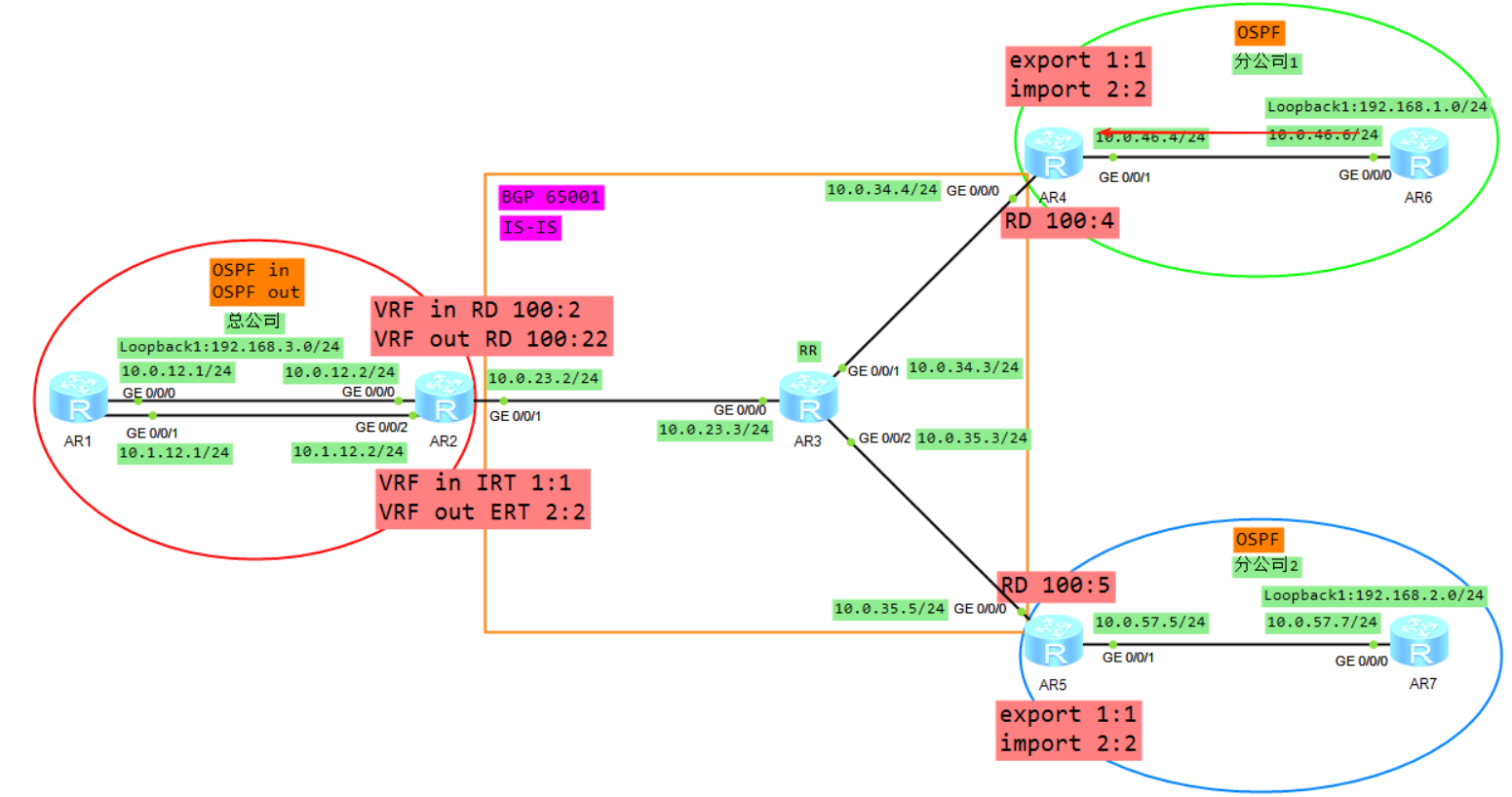
1、R6将业务路由1.0通过OSPF传递给R4,R4在实例A下面计算1.0的OSPF路由
2、R4将VRF A学习来的OSPF的路由引入到VRFA的BGP(VRF空间)
3、R4将BGP的路由添加RD RT 标签变成VPNV4的路由(Public)
4、R4将VPNV4的路由传递给自己的VPNV4邻居R2,当然因为AR3是RR所以AR3也会将R4转发给R2的路由转发给AR5,但是AR5因为RT值的缘故并不会接收。
5、R2根据VRF in 配置的IRT首先判断是否需要将VPNV4的路由接收进来放入到public
6、将VPNV4的路由去掉RD,放入到VRF in的BGP转发表
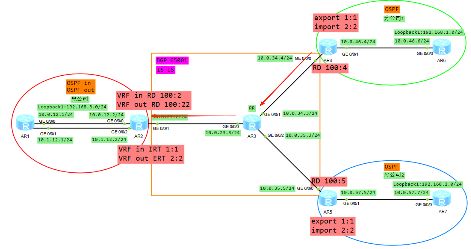
7、将VRF in的BGP的路由表引入到OSPF,生成LSA3(192.168.1.0)传递给R1的G0/0/0接口
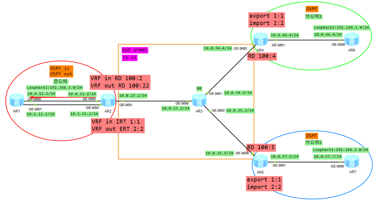
8、R1将LSA3从子接口2泛洪给R2的VRF out,R2的VRF out会计算一条192.168.1.0的OSPF路由(必须关闭DN比特位防环),然后将VRF out下的OSPF路由引入到VRF out的BGP下面
9、Vrf out下面BGP路由192.168.1.0,加上RD RT label 变成VPNV4路由传递给R5
10、R5通过配置VRF B的IRT,然后放入到VPNV4路由表(public)
11、将VPNV4的路由放入到VRFB,R5计算一条192.168.1.0的BGP路由
12、将VRFB的BGP引入到OSPF,生成LSA3(192.168.1.0)发给R7
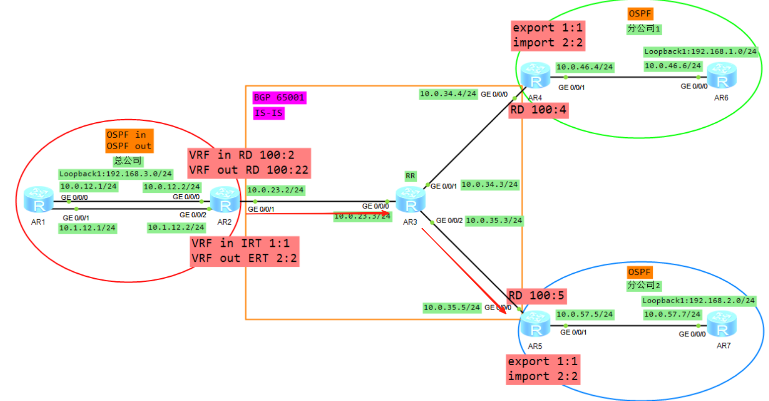
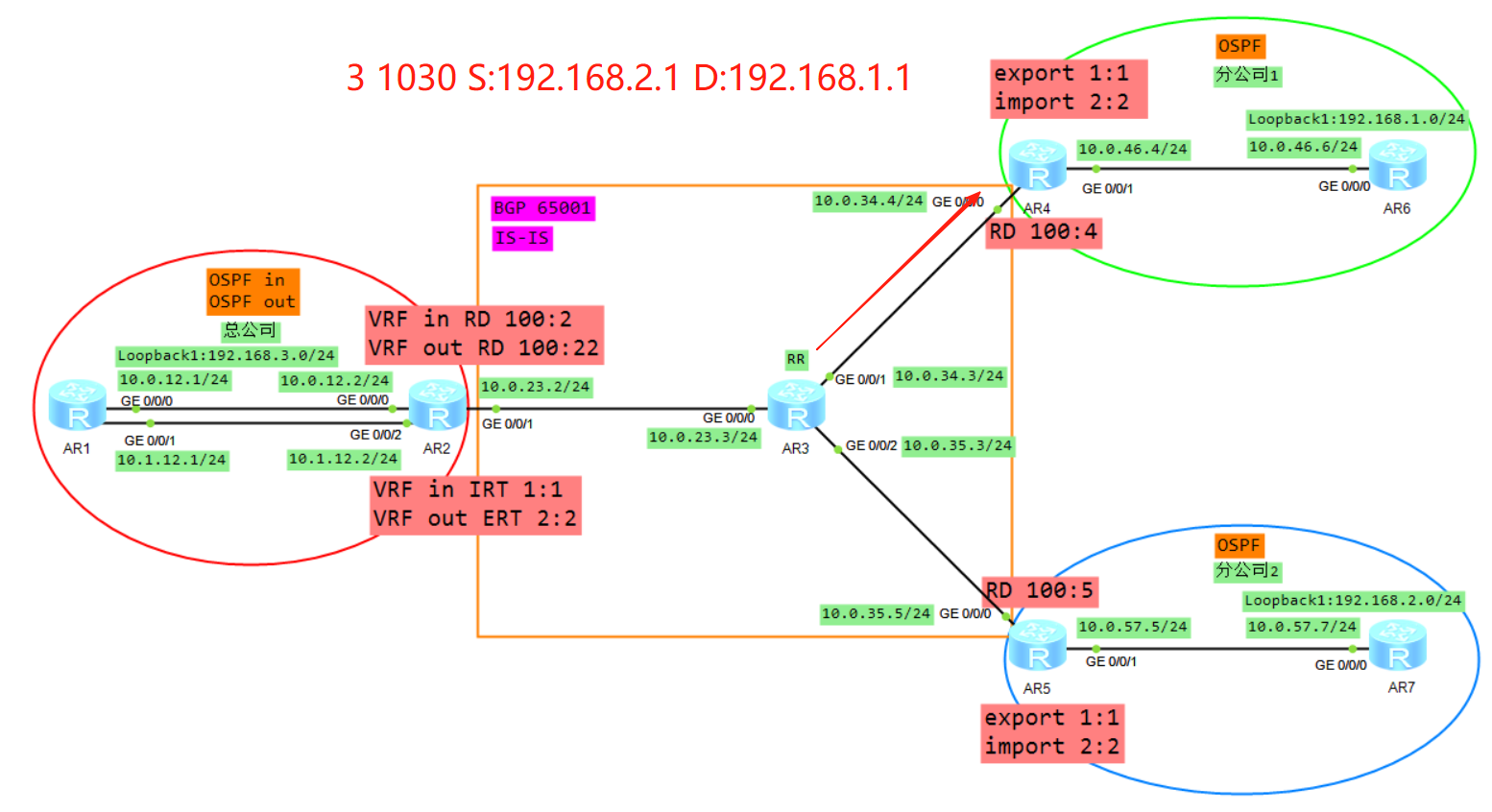
三、数据平面通信过程
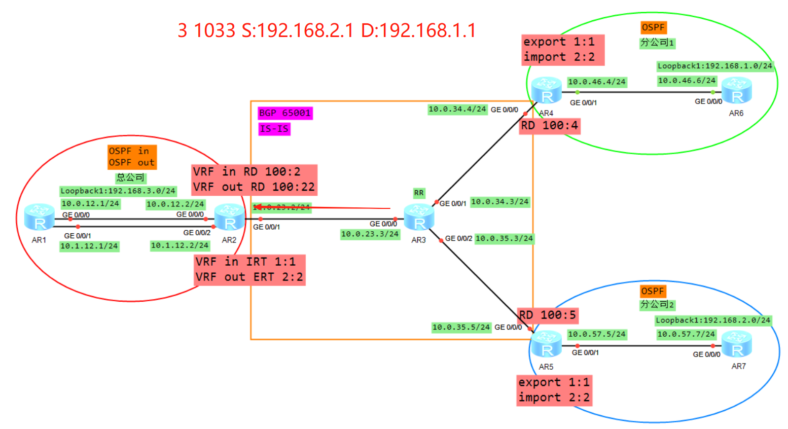
1、AR7发送报文
源IP为192.168.2.1目的IP为192.168.1.1的IP报文,根据路由表发送给AR5

2、AR5收到报文
AR5从实例B收到该报文,根据实例B的FIB表进行转发
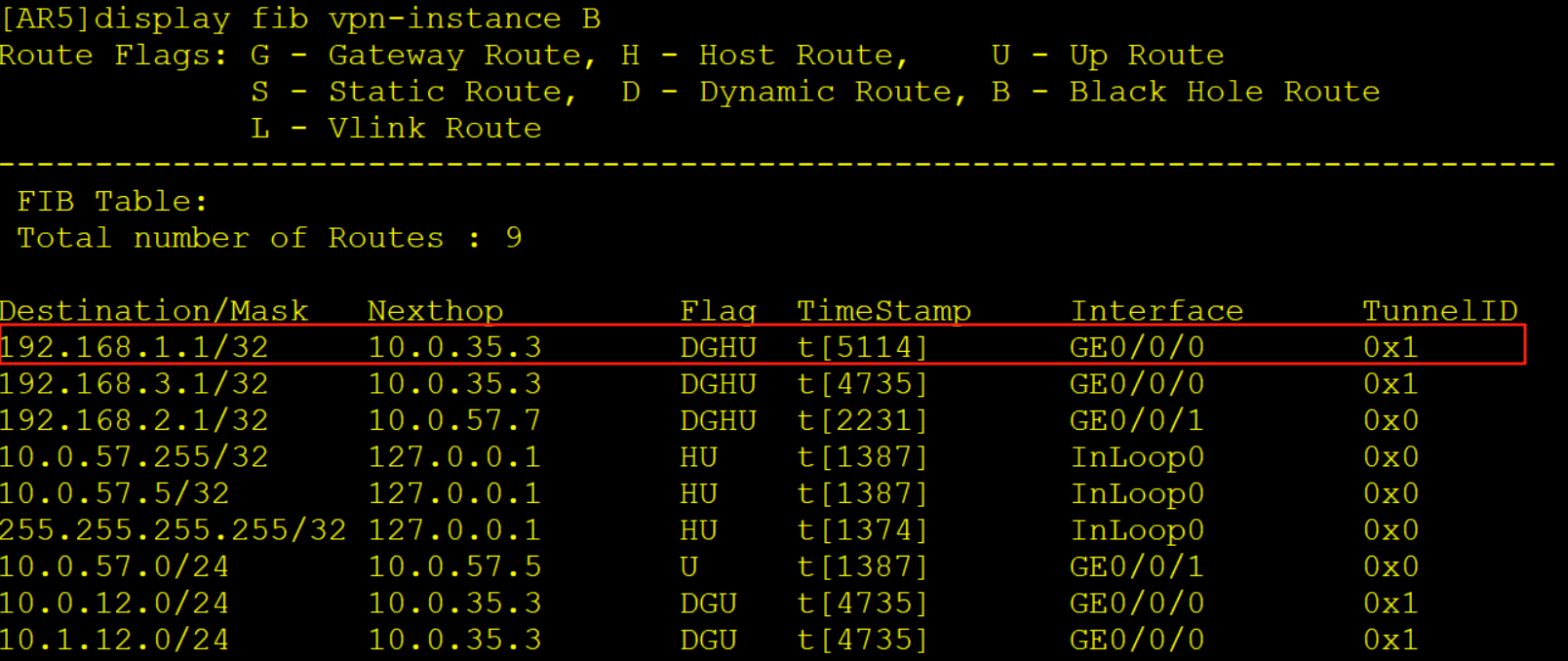
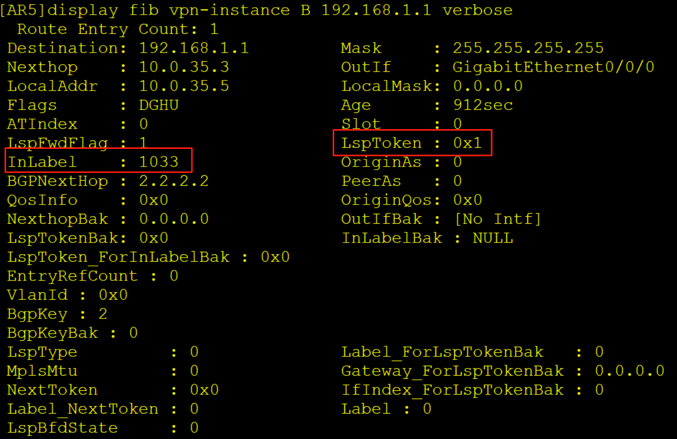
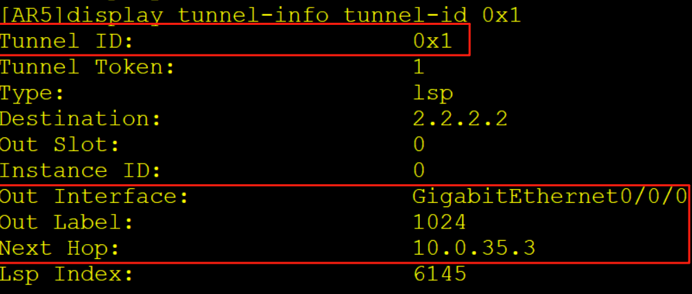
AR5查看实例B的FIB表项压入一个内层标签1033,一个外层标签1024,同时从G0/0/0口解析10.0.35.3的MAC,随后从G0/0/0口发出
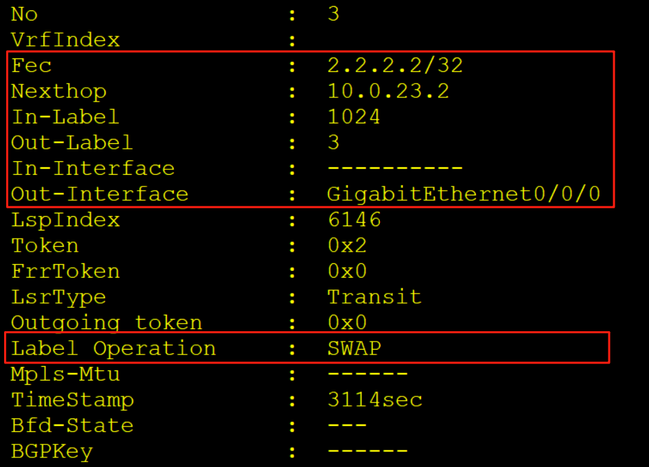
3、AR3收到报文
AR3收到该报文后,查看标签转发表LFIB,进行标签交换操作隧道从对应接口发出
4、AR2收到报文
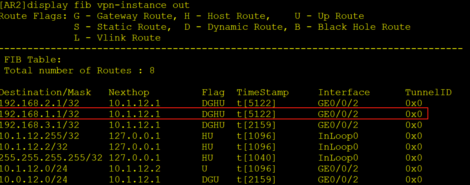
AR2收到该报文后,查标签转发表项LFIB,将标签弹出露出内层标签,继续查标签转发表项将内层标签弹出放入到实例out当中
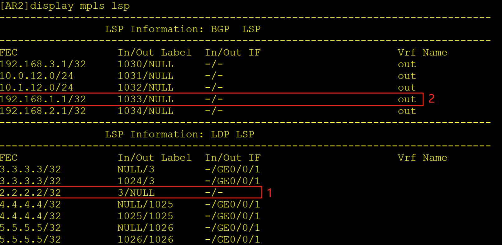
查看实例out的FIB表将报文转发给AR1
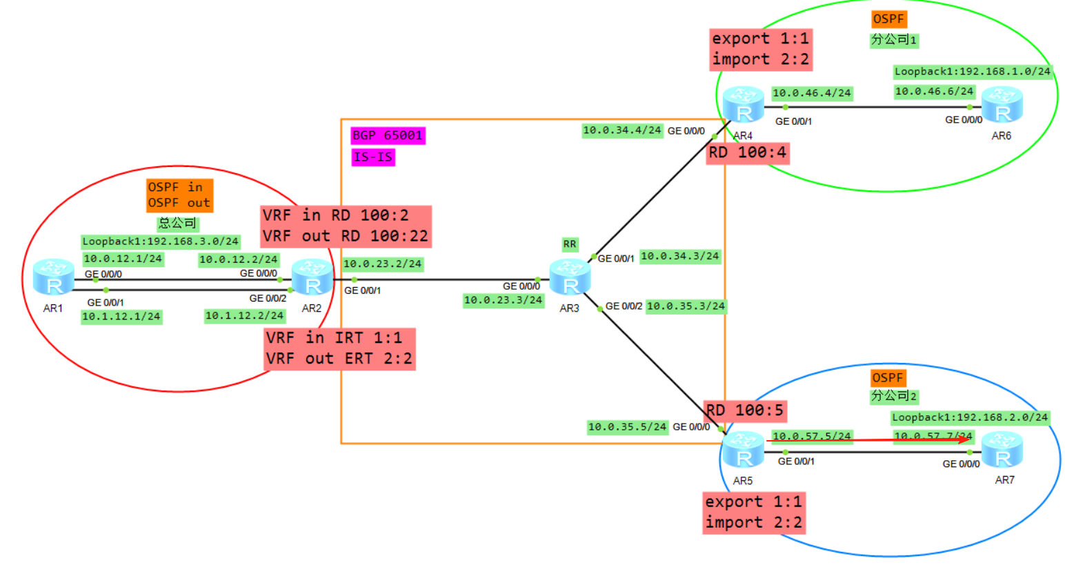
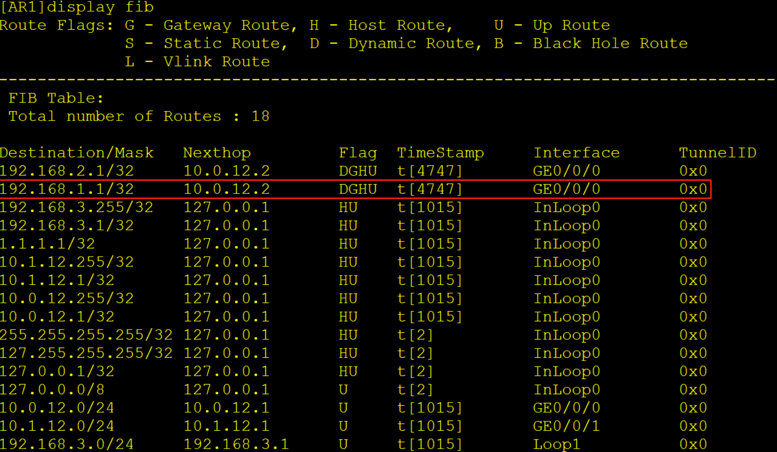
5、AR1收到报文
AR1收到该报文后查询FIB表项将报文转发给AR2的实例in当中
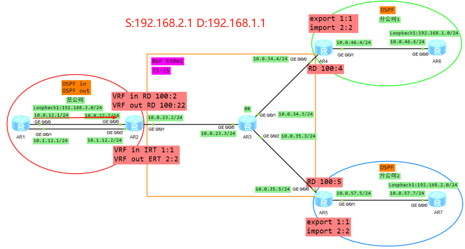
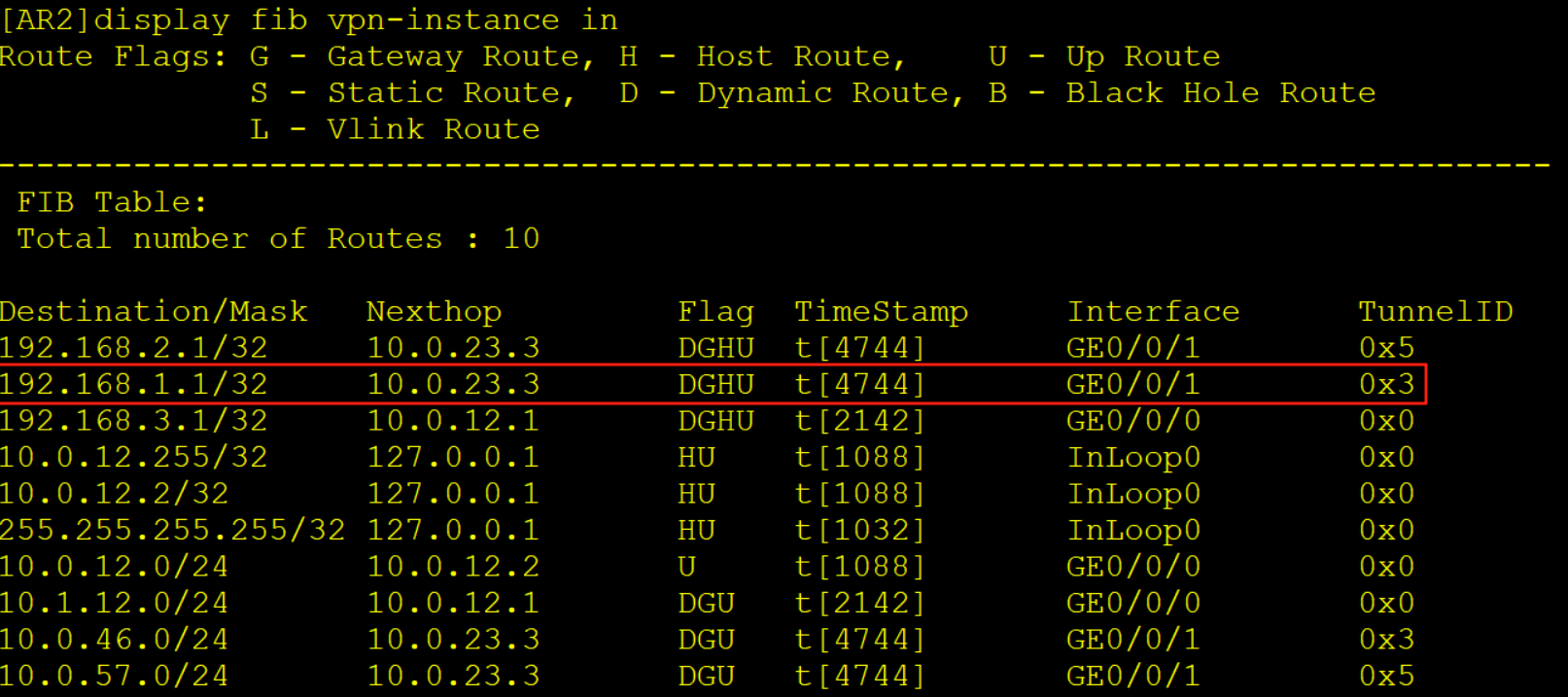
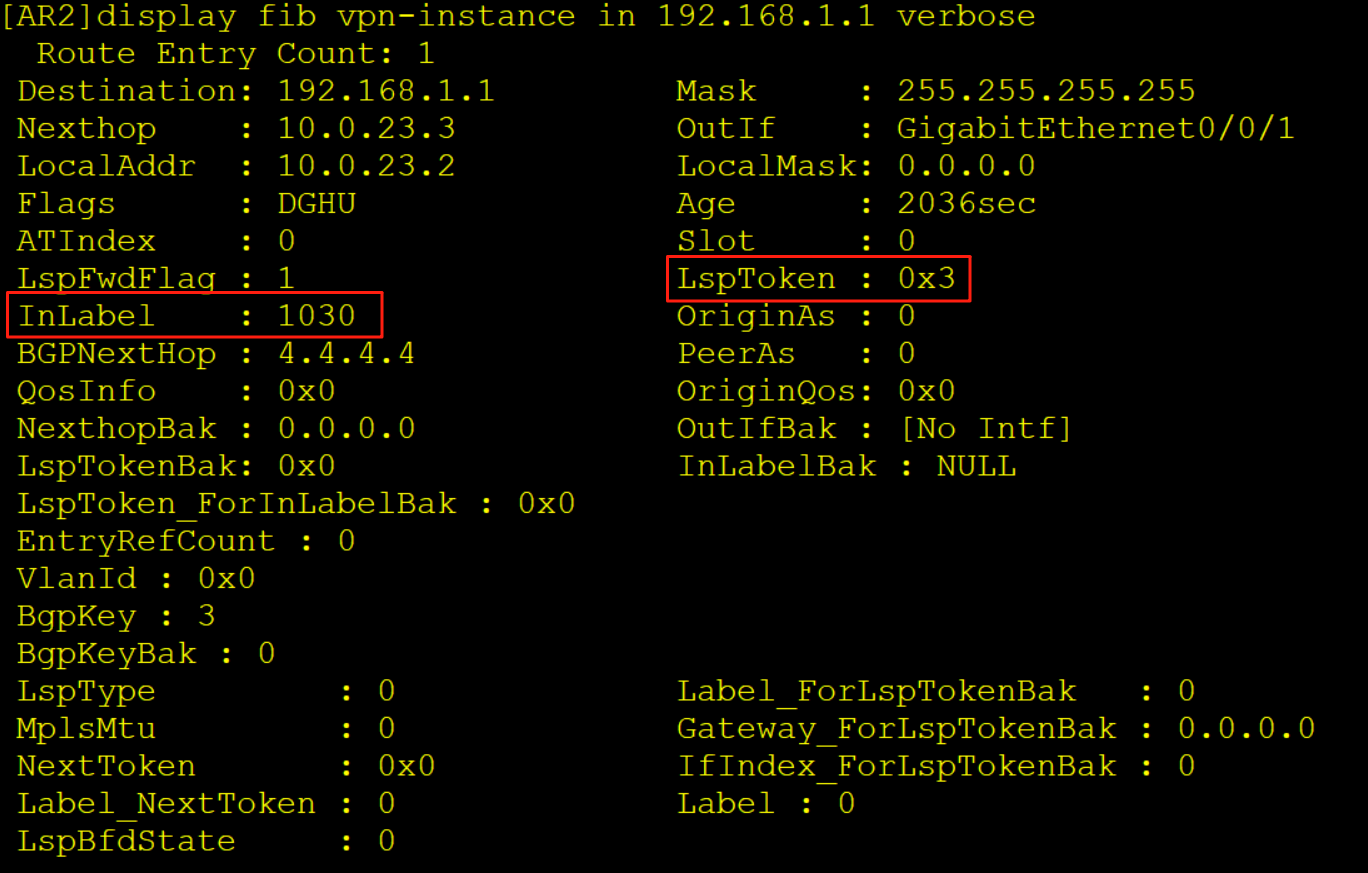
6、AR2收到报文
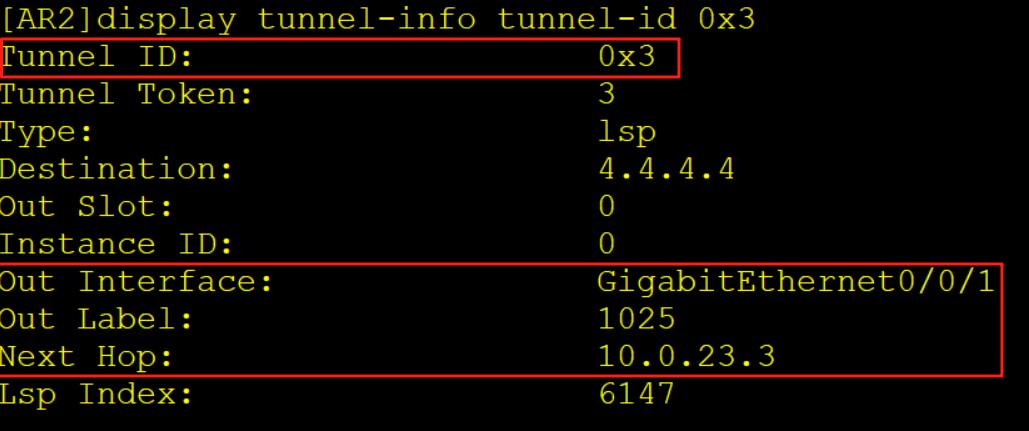
AR2收到该报文后查询实例in的FIB表项,压入一个内层标签1030,一个外层标签1025,同时去解析10.0.23.3的MAC从G0/0/1口转发给AR3。
7、AR3收到报文
AR3收到该报文后查询标签转发表LFIB,交换标签同时解析10.0.34.4的MAC从G0/0/1口转发给AR4
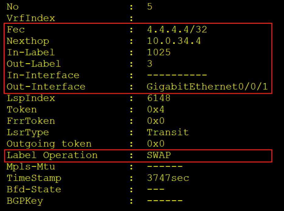
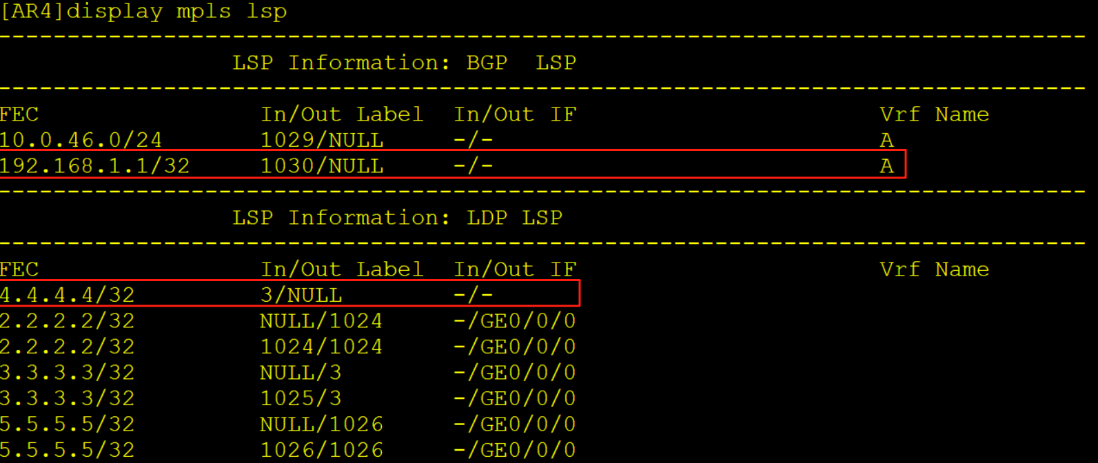
8、AR4收到报文
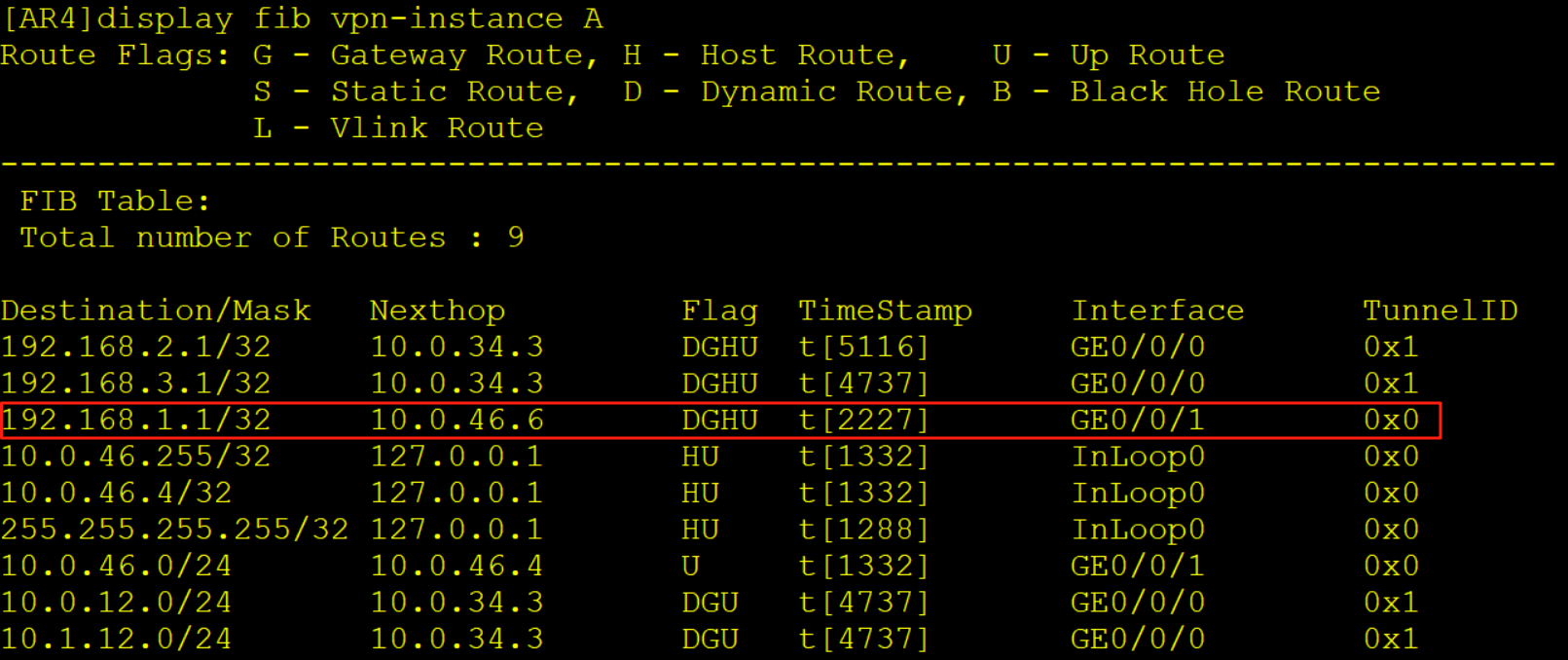
AR4收到该报文后查询LFIB标签转发表,弹出外层标签露出内层1030标签,继续查询标签转发表项,将内层标签弹出放入实例A当中,查询实例A的FIB表项将报文转发给AR6,此时该报文已经没有任何标签了。
以上就是本章的全部内容了,如果本文章对你的学习有帮助麻烦点个赞加个收藏,文章若有错误或疑问可联系博主删除更改,感谢大家的浏览观看!