DAC 简介
DAC(Digital to Analog Converter):将 MCU 中的数字信号(如 04095)转换为对应的模拟电压输出(03.3V)。
📚 资料推荐
💡 STM32F1 DAC 应用手册(ST 官方)
📘 HAL DAC Waveform Generation 示例
📦 CubeMX 中 DAC + DMA + TIM 正弦波输出示例
🔧 用 STM32 输出音频的 DAC 案例(.wav 文件播放)

STM32 DAC 特性(以 STM32F103 为例)
分辨率:12 位(0~4095)
通道数:2 路(DAC_OUT1、DAC_OUT2)
输出范围:0 ~ VREF(通常是 3.3V)
支持触发方式:软件、定时器、外部中断
可配合DMA 输出连续波形
CubeMX 配置说明
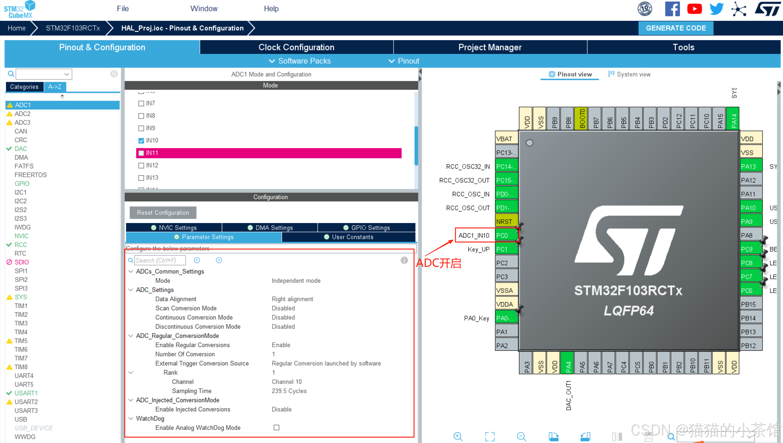
ADC 配置(如下图) :
通道:ADC1_IN10(PC0)
模式:Independent mode
触发方式:软件触发
采样时间设为 239.5 cycles(更稳定)
HAL库中 DAC 的使用流程
| 步骤 | 函数 |
|---|---|
| 1️⃣ 初始化 DAC | MX_DAC_Init() |
| 2️⃣ 启动 DAC 通道 | HAL_DAC_Start() |
| 3️⃣ 设置 DAC 输出值 | HAL_DAC_SetValue() |
| 4️⃣ 可选:DMA 输出波形 | HAL_DAC_Start_DMA() |
| 5️⃣ 可选:定时器控制输出频率 | Trigger = TIMx_TRGO |
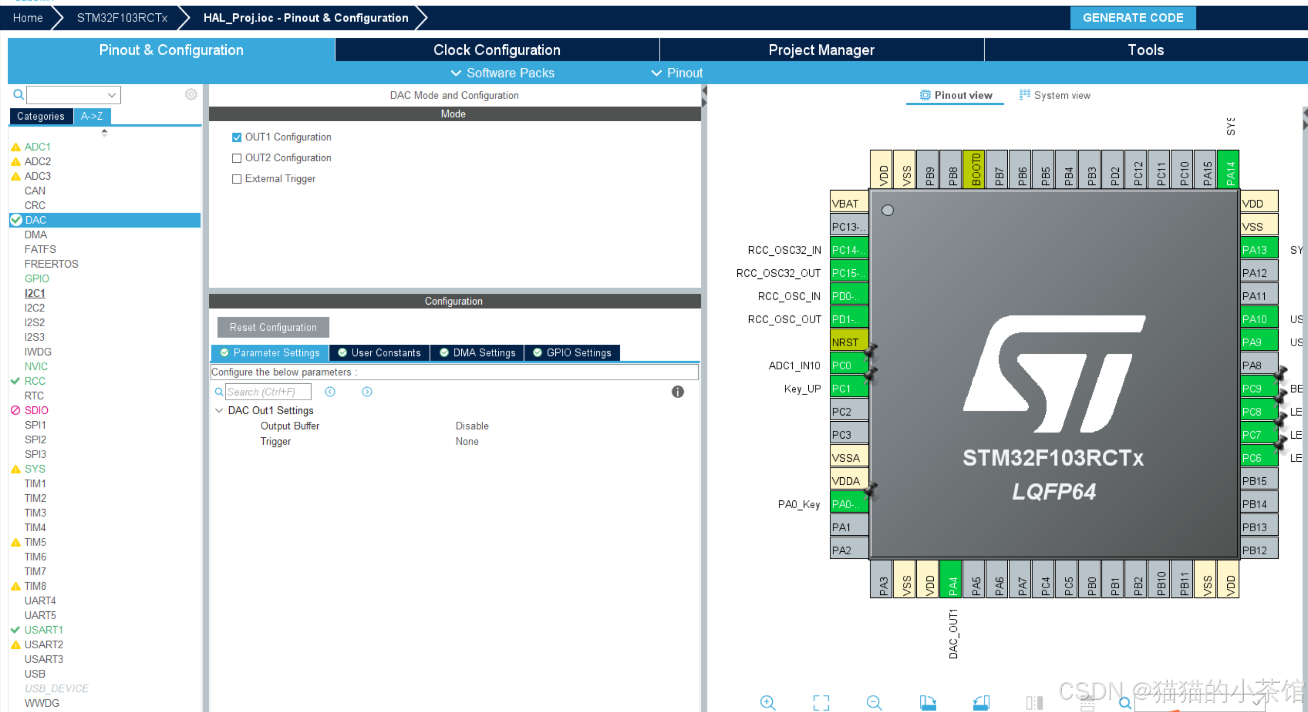
DAC 配置(如下图) :
OUT1:启用
Trigger:None(软件触发)
Output Buffer:Disable(默认关闭)
📌 DAC_OUT1 对应引脚:PA4
HAL 代码结构
当前介绍是完成 STM32 中 ADC(模数转换)+ DAC(数模转换) 的双向转换实验。 写代码的时候一定要保证代码结构清晰,CubeMX 配置也要非常规范。我们理解每个知识点务必要遵循:任务目标 ------> 整体结构和原理 ------> CubeMX 配置 ------> HAL 实现 ------> 运行效果 ------> 流程优化 ------> 需求迭代和更新。
✅ DAC 初始化和启动
c
HAL_DAC_Start(&hdac, DAC_CHANNEL_1); // 启用 DAC 通道 1
HAL_DAC_SetValue(&hdac, DAC_CHANNEL_1, DAC_ALIGN_12B_R, 0); // 初始输出为 0
DAC_ALIGN_12B_R:12 位右对齐(最大值 4095)
输出电压计算:
c
Vout = (dac_setval / 4095.0) * VREF✅ DAC 输出值渐变逻辑
输出电压从 0V → 3.3V → 0V 逐渐变化。
每秒更新一次,配合 ADC 采样观察变化曲线。
c
if ((dac_setval < 4095) && (Data_dir == 0)) dac_setval++;
if ((dac_setval > 0)    && (Data_dir == 1)) dac_setval--;

if (dac_setval >= 4095) Data_dir = 1;
if (dac_setval == 0)    Data_dir = 0;

HAL_DAC_SetValue(&hdac, DAC_CHANNEL_1, DAC_ALIGN_12B_R, dac_setval);
实验工作原理
步骤:
① DAC 输出从 0 → 4095(0~3.3V)
② DAC_OUT1(PA4)连接到 ADC_IN10(PC0)
③ ADC 采样电压,转换为数字值
④ UART 串口输出 ADC_Value
⑤ 实时观察 DAC 输出变化对 ADC 的影响
完整代码
📄 main.c
c
/* USER CODE BEGIN Header */
/**
  ******************************************************************************
  * @file           : main.c
  * @brief          : Main program body
  ******************************************************************************
  * @attention
  *
  * Copyright (c) 2025 STMicroelectronics.
  * All rights reserved.
  *
  * This software is licensed under terms that can be found in the LICENSE file
  * in the root directory of this software component.
  * If no LICENSE file comes with this software, it is provided AS-IS.
  *
  ******************************************************************************
  */
/* USER CODE END Header */
/* Includes ------------------------------------------------------------------*/
#include "main.h"
#include "adc.h"
#include "dac.h"
#include "usart.h"
#include "gpio.h"

/* Private includes ----------------------------------------------------------*/
/* USER CODE BEGIN Includes */
#include "string.h"
/* USER CODE END Includes */

/* Private typedef -----------------------------------------------------------*/
/* USER CODE BEGIN PTD */

/* USER CODE END PTD */

/* Private define ------------------------------------------------------------*/
/* USER CODE BEGIN PD */
/* USER CODE END PD */

/* Private macro -------------------------------------------------------------*/
/* USER CODE BEGIN PM */

/* USER CODE END PM */

/* Private variables ---------------------------------------------------------*/

/* USER CODE BEGIN PV */

/* USER CODE END PV */

/* Private function prototypes -----------------------------------------------*/
void SystemClock_Config(void);
/* USER CODE BEGIN PFP */

/* USER CODE END PFP */

/* Private user code ---------------------------------------------------------*/
/* USER CODE BEGIN 0 */
uint16_t ADC_Value = 0;

uint16_t dac_setval = 0;

uint8_t Data_dir = 0;
/* USER CODE END 0 */

/**
  * @brief  The application entry point.
  * @retval int
  */
int main(void)
{
  /* USER CODE BEGIN 1 */
  /* USER CODE END 1 */

  /* MCU Configuration--------------------------------------------------------*/

  /* Reset of all peripherals, Initializes the Flash interface and the Systick. */
  HAL_Init();

  /* USER CODE BEGIN Init */

  /* USER CODE END Init */

  /* Configure the system clock */
  SystemClock_Config();

  /* USER CODE BEGIN SysInit */

  /* USER CODE END SysInit */

  /* Initialize all configured peripherals */
  MX_GPIO_Init();
  MX_USART1_UART_Init();
  MX_ADC1_Init();
  MX_DAC_Init();
  /* USER CODE BEGIN 2 */
	HAL_UARTEx_ReceiveToIdle_IT(  &huart1 , U1RxData, U1RxDataSize);

	HAL_ADCEx_Calibration_Start( &hadc1 );  //开启校准

	HAL_DAC_Start( &hdac, DAC_CHANNEL_1); //开启DAC通道 输出使能
	HAL_DAC_SetValue( &hdac, DAC_CHANNEL_1 , DAC_ALIGN_12B_R, 0);  //设置DAC输出的初始值为 0

  /* USER CODE END 2 */

  /* Infinite loop */
  /* USER CODE BEGIN WHILE */

  while (1)
  {
		if((dac_setval < 4095) && (Data_dir == 0))   dac_setval++;
		if((dac_setval > 0)    && (Data_dir == 1))   dac_setval--;


		if(dac_setval > 4095)
		{
			dac_setval = 4095;
			Data_dir = 1;
		}
		if(dac_setval <= 0)
		{
			dac_setval = 0;
			Data_dir = 0;
		}
		printf(" dac_setval = %d \r\n",dac_setval);
		HAL_DAC_SetValue( &hdac, DAC_CHANNEL_1 , DAC_ALIGN_12B_R, dac_setval);


		HAL_ADC_Start( &hadc1 );  //开启ADC转换
		HAL_ADC_PollForConversion( &hadc1, 50); //等待转换完成

		if(HAL_IS_BIT_SET( HAL_ADC_GetState( &hadc1 ), HAL_ADC_STATE_REG_EOC) ) //判断是否转换完成
		{
			ADC_Value = HAL_ADC_GetValue(&hadc1);

			printf(" ADC_Value = %d \r\n",ADC_Value);
		}

		HAL_Delay(1000);

    /* USER CODE END WHILE */

    /* USER CODE BEGIN 3 */
  }
  /* USER CODE END 3 */
}

/**
  * @brief System Clock Configuration
  * @retval None
  */
void SystemClock_Config(void)
{
  RCC_OscInitTypeDef RCC_OscInitStruct = {0};
  RCC_ClkInitTypeDef RCC_ClkInitStruct = {0};
  RCC_PeriphCLKInitTypeDef PeriphClkInit = {0};

  /** Initializes the RCC Oscillators according to the specified parameters
  * in the RCC_OscInitTypeDef structure.
  */
  RCC_OscInitStruct.OscillatorType = RCC_OSCILLATORTYPE_HSE;
  RCC_OscInitStruct.HSEState = RCC_HSE_ON;
  RCC_OscInitStruct.HSEPredivValue = RCC_HSE_PREDIV_DIV1;
  RCC_OscInitStruct.HSIState = RCC_HSI_ON;
  RCC_OscInitStruct.PLL.PLLState = RCC_PLL_ON;
  RCC_OscInitStruct.PLL.PLLSource = RCC_PLLSOURCE_HSE;
  RCC_OscInitStruct.PLL.PLLMUL = RCC_PLL_MUL9;
  if (HAL_RCC_OscConfig(&RCC_OscInitStruct) != HAL_OK)
  {
    Error_Handler();
  }

  /** Initializes the CPU, AHB and APB buses clocks
  */
  RCC_ClkInitStruct.ClockType = RCC_CLOCKTYPE_HCLK|RCC_CLOCKTYPE_SYSCLK
                              |RCC_CLOCKTYPE_PCLK1|RCC_CLOCKTYPE_PCLK2;
  RCC_ClkInitStruct.SYSCLKSource = RCC_SYSCLKSOURCE_PLLCLK;
  RCC_ClkInitStruct.AHBCLKDivider = RCC_SYSCLK_DIV1;
  RCC_ClkInitStruct.APB1CLKDivider = RCC_HCLK_DIV2;
  RCC_ClkInitStruct.APB2CLKDivider = RCC_HCLK_DIV1;

  if (HAL_RCC_ClockConfig(&RCC_ClkInitStruct, FLASH_LATENCY_2) != HAL_OK)
  {
    Error_Handler();
  }
  PeriphClkInit.PeriphClockSelection = RCC_PERIPHCLK_ADC;
  PeriphClkInit.AdcClockSelection = RCC_ADCPCLK2_DIV6;
  if (HAL_RCCEx_PeriphCLKConfig(&PeriphClkInit) != HAL_OK)
  {
    Error_Handler();
  }
}

/* USER CODE BEGIN 4 */

/* USER CODE END 4 */

/**
  * @brief  This function is executed in case of error occurrence.
  * @retval None
  */
void Error_Handler(void)
{
  /* USER CODE BEGIN Error_Handler_Debug */
  /* User can add his own implementation to report the HAL error return state */
  __disable_irq();
  while (1)
  {
  }
  /* USER CODE END Error_Handler_Debug */
}

#ifdef  USE_FULL_ASSERT
/**
  * @brief  Reports the name of the source file and the source line number
  *         where the assert_param error has occurred.
  * @param  file: pointer to the source file name
  * @param  line: assert_param error line source number
  * @retval None
  */
void assert_failed(uint8_t *file, uint32_t line)
{
  /* USER CODE BEGIN 6 */
  /* User can add his own implementation to report the file name and line number,
     ex: printf("Wrong parameters value: file %s on line %d\r\n", file, line) */
  /* USER CODE END 6 */
}
#endif /* USE_FULL_ASSERT */
测试验证:
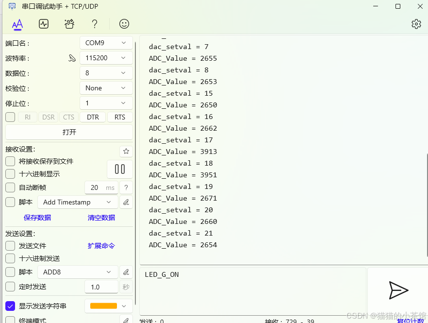
验证 DAC+ADC 的结果:
还可以采用其他方法观测结果是否正确:
万用表测 PA4 电压				随 dac_setval 上下变化(0~3.3V)
ADC 采样值与 DAC 输出对应		理论上 ADC_Value ≈ dac_setval(误差几位)
串口观察输出					ADC_Value 随 dac_setval 对称变化
示波器观测					输出电压呈锯齿波形(线性上升下降)
以上。 这便是 STM32 中 ADC(模数转换)+ DAC(数模转换) 的双向转换实验 的实现。
以上,欢迎有从事同行业的电子信息工程、互联网通信、嵌入式开发的朋友共同探讨与提问,我可以提供实战演示或模板库。希望内容能够对你产生帮助!