1. 引言
Vericut是一款专业的数控加工仿真软件,广泛应用于航空航天、汽车制造和精密加工等领域。MCH(Machine Configuration)文件是Vericut中定义机床几何结构、运动学参数和控制系统配置的核心文件。本文将通过一个典型的5轴联动加工中心配置实例,深入解析MCH文件的结构和构建方法。
该机床采用典型的"双摆台"结构,工件安装在B轴和C轴(实际为A轴)组成的双转台上,刀具通过Z轴和Y轴进行线性运动。这种结构特别适合于复杂曲面零件的多角度加工,是航空航天领域叶片、叶盘等零件加工的常用配置。
2. MCH文件基础结构
MCH文件采用XML格式,包含机床的基本信息、组件定义、运动链关系和几何模型等核心内容。以下是完整的基础结构框架:
xml
<?xml version="1.0"?>
<VcMachine Version="9.1.1" Machine="5Am" Unit="millimeter">
  <!-- 文件信息部分 -->
  <Information>
    <InfoUserName>Workstation</InfoUserName>
    <InfoDateTime>Mon Jul  7 17:03:44 2025</InfoDateTime>
    <InfoVericutVersion>9.5</InfoVericutVersion>
    <InfoBuildDate>June 20, 2024</InfoBuildDate>
    <InfoLibraryDate>06/20/24</InfoLibraryDate>
  </Information>

  <!-- 运动优先级类型 -->
  <PriorityType>single</PriorityType>

  <!-- 碰撞检测设置 -->
  <Collision>
  </Collision>

  <!-- 机床组件定义区域 -->
  <!-- 各组件将在后续详细定义 -->

  <!-- 预览图像 -->
  <Preview Image="iVBORw0KGgoAAAANSUhEUgAAAQAAAADYCAYAAAAEaD2QAACAAElEQVR4XuydB5RUxfb1WevziWSVLBJUcgYxgIAiOShIUHJO..."/>
</VcMachine>每个MCH文件都必须以<VcMachine>为根元素,其中Version属性指定Vericut版本兼容性,Machine属性定义机床名称,Unit属性设置全局单位系统。单位设置直接影响后续所有几何尺寸的解析,常用单位包括毫米(millimeter)和英寸(inch),其转换关系为:
1 inch = 25.4 mm 1\ \text{inch} = 25.4\ \text{mm} 1 inch=25.4 mm
3. 机床组件定义与运动学建模
机床组件是MCH文件的核心,每个组件通过<Component>元素定义,包含类型、可见性、运动参数和几何模型等信息。组件类型主要包括:
base:机床基础(床身)linear:线性运动轴rotary:旋转运动轴spindle:主轴组件tool:刀具安装点attach:工件夹具
3.1 基础组件定义
机床基础是运动链的参考基准,所有其他组件都直接或间接安装于基础之上。基础组件通常包含机床的主要结构几何模型:
xml
<Component Name="Base"
 Subsystem="1"
 Type="base" Visible="machine" Enabled="on" Draw="shaded" XRGB="0x00A0A0A0">
  <Attach></Attach>
  <Position X="0" Y="0" Z="0"/>
  <Rotation I="0" J="0" K="0"/>
  <Appearance Name="Machine Component" Ambient="0.2" Diffuse="0.7"
              Reflect="0.2" Specular="1" Shininess="6"
              Translucency="1" XRGB="0x00A0A0A0"/>
  <STL Unit="millimeter" Normal="outward" Visible="on" Enabled="on"
       HasOpenSurface="off" XRGB="0x0040E0D0">
    <File>G:\54yuikAm\床身.stl</File>
    <Appearance Name="Machine Component" Ambient="0.2" Diffuse="0.7"
                Reflect="0.2" Specular="1" Shininess="6"
                Translucency="1" XRGB="0x0040E0D0"/>
    <EdgeAngle>30</EdgeAngle>
    <ModelMatrix>
      <MatrixXAxis X="1" Y="0" Z="0"/>
      <MatrixYAxis X="0" Y="1" Z="0"/>
      <MatrixZAxis X="0" Y="0" Z="1"/>
      <MatrixOrigin X="0" Y="0" Z="0"/>
    </ModelMatrix>
  </STL>
</Component>组件的位置和方向通过<Position>和<Rotation>元素定义。位置使用笛卡尔坐标系 ( X , Y , Z ) (X, Y, Z) (X,Y,Z)表示,旋转采用欧拉角 ( I , J , K ) (I, J, K) (I,J,K)系统,分别绕X、Y、Z轴旋转。旋转矩阵 R R R的计算公式为:
R = R z ( K ) ⋅ R y ( J ) ⋅ R x ( I ) R = R_z(K) \cdot R_y(J) \cdot R_x(I) R=Rz(K)⋅Ry(J)⋅Rx(I)
其中绕X、Y、Z轴的旋转矩阵分别为:
R x ( θ ) = 1 0 0 0 cos θ − sin θ 0 sin θ cos θ R_x(\theta) = \begin{bmatrix} 1 & 0 & 0 \\ 0 & \cos\theta & -\sin\theta \\ 0 & \sin\theta & \cos\theta \end{bmatrix} Rx(θ)=⎣⎡1000cosθsinθ0−sinθcosθ⎦⎤
R y ( θ ) = cos θ 0 sin θ 0 1 0 − sin θ 0 cos θ R_y(\theta) = \begin{bmatrix} \cos\theta & 0 & \sin\theta \\ 0 & 1 & 0 \\ -\sin\theta & 0 & \cos\theta \end{bmatrix} Ry(θ)=⎣⎡cosθ0−sinθ010sinθ0cosθ⎦⎤
R z ( θ ) = cos θ − sin θ 0 sin θ cos θ 0 0 0 1 R_z(\theta) = \begin{bmatrix} \cos\theta & -\sin\theta & 0 \\ \sin\theta & \cos\theta & 0 \\ 0 & 0 & 1 \end{bmatrix} Rz(θ)=⎣⎡cosθsinθ0−sinθcosθ0001⎦⎤
3.2 线性轴组件
线性轴组件定义机床的平移运动,包括X、Y、Z轴。每个线性轴通过<Link>元素定义运动参数:
xml
<Component Name="X"
 Subsystem="1"
 Type="linear" Visible="machine" Enabled="on" Draw="shaded" XRGB="0x00A0A0A0">
  <Attach>Base</Attach>
  <Position X="0" Y="0" Z="0"/>
  <Rotation I="0" J="0" K="0"/>
  <Appearance Name="Machine Component" Ambient="0.2" Diffuse="0.7"
              Reflect="0.2" Specular="1" Shininess="6"
              Translucency="1" XRGB="0x00A0A0A0"/>
  <Link Axis="-X" PartSide="auto" Register="X"
   RapidRate="5000" Accel="125" Decel="125"
   MaxLinearVelocity="5000" MaxCornerVelocity="600">
    <AxisPriority PriorityGroup="0" PriorityPos="1"
                  InterpolatedPos="on" PriorityNeg="1" InterpolatedNeg="on"/>
  </Link>
  <STL Unit="millimeter" Normal="outward" Visible="on" Enabled="on"
       HasOpenSurface="off" XRGB="0x007CFC00">
    <File>G:\5Am\X轴.stl</File>
    <Appearance Name="Machine Component" Ambient="0.2" Diffuse="0.7"
                Reflect="0.2" Specular="1" Shininess="6"
                Translucency="1" XRGB="0x007CFC00"/>
    <EdgeAngle>30</EdgeAngle>
    <ModelMatrix>
      <MatrixXAxis X="1" Y="0" Z="0"/>
      <MatrixYAxis X="0" Y="1" Z="0"/>
      <MatrixZAxis X="0" Y="0" Z="1"/>
      <MatrixOrigin X="0" Y="0" Z="0"/>
    </ModelMatrix>
  </STL>
</Component>运动参数中,RapidRate定义快速移动速度,Accel和Decel分别定义加速度和减速度,MaxLinearVelocity限制最大线速度,MaxCornerVelocity控制拐角处最大速度。这些参数直接影响加工效率和表面质量。
对于线性插补运动,当机床同时移动多个轴时,各轴的实际速度 v i v_i vi需要满足:
v i = Δ L i T ≤ v i , max v_i = \frac{\Delta L_i}{T} \leq v_{i,\text{max}} vi=TΔLi≤vi,max
其中 Δ L i \Delta L_i ΔLi为第 i i i轴的移动距离, T T T为运动时间, v i , max v_{i,\text{max}} vi,max为该轴的最大允许速度。
3.3 旋转轴组件
旋转轴组件定义机床的旋转运动,通常为A、B、C轴。旋转轴的运动参数与线性轴类似,但运动类型为旋转:
xml
<Component Name="B"
 Subsystem="1"
 Type="rotary" Visible="machine" Enabled="on" Draw="shaded"
 XRGB="0x00A0A0A0" RotarySpin="off">
  <Attach>X</Attach>
  <Position X="0" Y="0" Z="0"/>
  <Rotation I="180" J="0" K="180"/>
  <Appearance Name="Machine Component" Ambient="0.2" Diffuse="0.7"
              Reflect="0.2" Specular="1" Shininess="6"
              Translucency="1" XRGB="0x00A0A0A0"/>
  <Link Axis="Y" PartSide="auto" Register="B"
   RapidRate="5000" Accel="125" Decel="125"
   MaxLinearVelocity="5000" MaxCornerVelocity="600">
    <AxisPriority PriorityGroup="0" PriorityPos="1"
                  InterpolatedPos="on" PriorityNeg="1" InterpolatedNeg="on"/>
  </Link>
  <STL Unit="millimeter" Normal="outward" Visible="on" Enabled="on"
       HasOpenSurface="off" XRGB="0x00FFFFFF">
    <File>G:\5Am\B轴.stl</File>
    <Appearance Name="Machine Component" Ambient="0.2" Diffuse="0.7"
                Reflect="0.2" Specular="1" Shininess="6"
                Translucency="1" XRGB="0x00FFFFFF"/>
    <EdgeAngle>30</EdgeAngle>
    <ModelMatrix>
      <MatrixXAxis X="6.12323399574e-17" Y="0" Z="-1"/>
      <MatrixYAxis X="0" Y="1" Z="0"/>
      <MatrixZAxis X="1" Y="0" Z="6.12323399574e-17"/>
      <MatrixOrigin X="0" Y="0" Z="0"/>
    </ModelMatrix>
  </STL>
</Component>旋转轴的Rotation属性定义了组件的初始方向。示例中B轴的初始旋转为 I = 180 ° I=180° I=180°, K = 180 ° K=180° K=180°,这通常用于调整转台的初始姿态。旋转矩阵中的小数值(如 6.12323399574 × 1 0 − 17 6.12323399574 \times 10^{-17} 6.12323399574×10⁻¹⁷)实际上是浮点数计算误差,理论值应为0,表示由于有限精度计算产生的舍入误差。
对于5轴机床,旋转轴的运动范围通常有限制。B轴常见的运动范围为 − 120 ° -120° −120°到 + 120 ° +120° +120°,C轴为 0 ° 0° 0°到 360 ° 360° 360°连续旋转。这些限制需要在机床控制器中设置,并在Vericut中通过行程限制参数定义。
3.4 主轴和刀具组件
主轴组件是刀具的安装基准,刀具组件定义刀具的安装位置和方向:
xml
<Component Name="Spindle"
 Subsystem="1"
 Type="spindle" Visible="machine" Enabled="on" Draw="shaded" XRGB="0x00A0A0A0">
  <Attach>Y</Attach>
  <Position X="0" Y="0" Z="0"/>
  <Rotation I="0" J="0" K="0"/>
  <Appearance Name="Machine Component" Ambient="0.2" Diffuse="0.7"
              Reflect="0.2" Specular="1" Shininess="6"
              Translucency="1" XRGB="0x00A0A0A0"/>
  <Link Axis="Z" PartSide="no" Register="">
  </Link>
  <STL Unit="millimeter" Normal="outward" Visible="off" Enabled="on"
       HasOpenSurface="off" XRGB="0x80000000">
    <File>G:\5Am\主轴.stl</File>
    <EdgeAngle>30</EdgeAngle>
    <ModelMatrix>
      <MatrixXAxis X="1" Y="0" Z="0"/>
      <MatrixYAxis X="0" Y="1" Z="0"/>
      <MatrixZAxis X="0" Y="0" Z="1"/>
      <MatrixOrigin X="-162.9065" Y="110.58" Z="162.0667"/>
    </ModelMatrix>
  </STL>
</Component>
xml
<Component Name="Tool"
 Subsystem="1"
 Type="tool" Visible="all" Enabled="on" Draw="shaded" XRGB="0x00A0A0A0">
  <Attach>Spindle</Attach>
  <Position X="-162.9065" Y="110.58" Z="162.0667"/>
  <Rotation I="0" J="0" K="0"/>
  <Appearance Name="Machine Component" Ambient="0.2" Diffuse="0.7"
              Reflect="0.2" Specular="1" Shininess="6"
              Translucency="1" XRGB="0x00A0A0A0"/>
  <Tool TurretIndex="1"/>
  <Link Axis="Z" PartSide="auto" Register="">
  </Link>
</Component>刀具位置(-162.9065, 110.58, 162.0667)定义了刀具相对于主轴的安装点。在5轴加工中,刀具中心点(Tool Center Point, TCP)的位置计算需要考虑所有运动轴的变换。对于本文的双摆台结构,工件坐标系到机床坐标系的变换矩阵为:
T machine = T base ⋅ T X ⋅ T B ⋅ T C ⋅ T workpiece T_{\text{machine}} = T_{\text{base}} \cdot T_X \cdot T_B \cdot T_C \cdot T_{\text{workpiece}} Tmachine=Tbase⋅TX⋅TB⋅TC⋅Tworkpiece
其中 T base T_{\text{base}} Tbase为机床基础变换, T X T_X TX为X轴变换, T B T_B TB为B轴变换, T C T_C TC为C轴变换, T workpiece T_{\text{workpiece}} Tworkpiece为工件坐标系变换。
4. 运动链分析与运动学计算
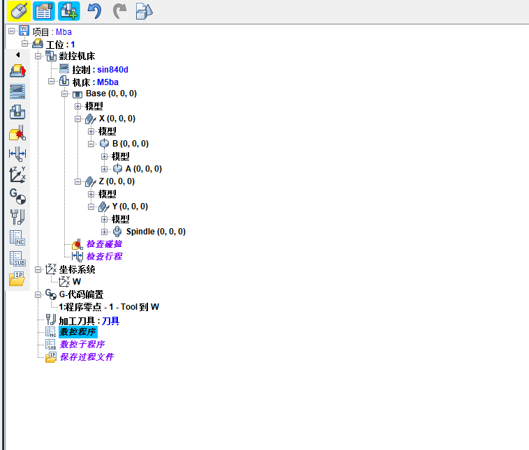
4.1 运动链结构分析
从MCH文件可以提取出完整的运动链结构:
xml
<!-- 工件侧运动链 -->
<Component Name="Base" Type="base">...</Component>
<Component Name="X" Type="linear" Attach="Base">...</Component>
<Component Name="B" Type="rotary" Attach="X">...</Component>
<Component Name="C" Type="rotary" Attach="B">...</Component>
<Component Name="Attach" Type="attach" Attach="C">...</Component>

<!-- 刀具侧运动链 -->
<Component Name="Base" Type="base">...</Component>
<Component Name="Z" Type="linear" Attach="Base">...</Component>
<Component Name="Y" Type="linear" Attach="Z">...</Component>
<Component Name="Spindle" Type="spindle" Attach="Y">...</Component>
<Component Name="Tool" Type="tool" Attach="Spindle">...</Component>
这种运动链结构在运动学上属于"混合型5轴机床",工件通过X、B、C三轴运动,刀具通过Z、Y两轴运动。运动学正解计算刀具中心点位置时,需要将刀具坐标系转换到工件坐标系:
P workpiece = ( T workpiece ) − 1 ⋅ ( T C ) − 1 ⋅ ( T B ) − 1 ⋅ ( T X ) − 1 ⋅ T base − 1 ⋅ T base ⋅ T Z ⋅ T Y ⋅ T spindle ⋅ P tool P_{\text{workpiece}} = (T_{\text{workpiece}})^{-1} \cdot (T_C)^{-1} \cdot (T_B)^{-1} \cdot (T_X)^{-1} \cdot T_{\text{base}}^{-1} \cdot T_{\text{base}} \cdot T_Z \cdot T_Y \cdot T_{\text{spindle}} \cdot P_{\text{tool}} Pworkpiece=(Tworkpiece)−1⋅(TC)−1⋅(TB)−1⋅(TX)−1⋅Tbase−1⋅Tbase⋅TZ⋅TY⋅Tspindle⋅Ptool
4.2 运动学逆解算法
对于5轴加工,通常给定刀具轴线方向向量 n ⃗ = ( n x , n y , n z ) \vec{n} = (n_x, n_y, n_z) n =(nx,ny,nz)和刀具中心点位置 P = ( x , y , z ) P = (x, y, z) P=(x,y,z),需要求解各轴位置 ( X , Y , Z , B , C ) (X, Y, Z, B, C) (X,Y,Z,B,C)。对于双摆台结构,逆解算法如下:
python
import numpy as np
import math

def inverse_kinematics_5axis(tool_position, tool_orientation, machine_params):
    """
    5轴机床逆运动学求解
    tool_position: 刀具中心点坐标 (x, y, z)
    tool_orientation: 刀具方向向量 (nx, ny, nz)
    machine_params: 机床结构参数
    返回: 各轴位置 (X, Y, Z, B, C)
    """
    # 提取机床参数
    pivot_distance = machine_params['pivot_distance']  # 转台旋转中心到工件坐标系原点距离
    tool_length = machine_params['tool_length']  # 刀具长度

    # 归一化刀具方向向量
    n = np.array(tool_orientation)
    n = n / np.linalg.norm(n)

    # 计算旋转轴角度
    # B轴角度计算(绕Y轴旋转)
    B = math.atan2(math.sqrt(n[0]**2 + n[2]**2), n[1])

    # C轴角度计算(绕Z轴旋转)
    if abs(B) < 1e-6:  # B接近0时,C角任意
        C = 0
    else:
        C = math.atan2(n[0], n[2])

    # 计算旋转矩阵
    R_B = np.array([
        [math.cos(B), 0, math.sin(B)],
        [0, 1, 0],
        [-math.sin(B), 0, math.cos(B)]
    ])

    R_C = np.array([
        [math.cos(C), -math.sin(C), 0],
        [math.sin(C), math.cos(C), 0],
        [0, 0, 1]
    ])

    # 完整旋转矩阵
    R = R_C @ R_B

    # 计算线性轴位置
    # 考虑转台旋转中心偏移
    pivot_offset = np.array([0, pivot_distance, 0])

    # 刀具在转台坐标系中的位置
    tool_in_rotary = np.array(tool_position) - pivot_offset

    # 反向旋转到初始位置
    tool_in_initial = R.T @ tool_in_rotary

    # 考虑刀具长度补偿
    tool_tip_offset = np.array([0, 0, -tool_length])
    tool_in_initial = tool_in_initial - tool_tip_offset

    # 提取线性轴位置
    X = tool_in_initial[0]
    Y = tool_in_initial[1] - machine_params['y_offset']  # Y轴偏移补偿
    Z = tool_in_initial[2]

    # 角度单位转换(弧度转度)
    B_deg = math.degrees(B)
    C_deg = math.degrees(C)

    return X, Y, Z, B_deg, C_deg

# 示例使用
machine_params = {
    'pivot_distance': 150.0,  # 转台旋转中心到工件距离
    'tool_length': 100.0,     # 刀具长度
    'y_offset': 110.58        # Y轴初始偏移
}

# 测试数据
tool_position = [100, 200, 150]
tool_orientation = [0, 0, 1]  # 垂直向下

result = inverse_kinematics_5axis(tool_position, tool_orientation, machine_params)
print(f"各轴位置: X={result[0]:.3f}, Y={result[1]:.3f}, Z={result[2]:.3f}, "
      f"B={result[3]:.3f}°, C={result[4]:.3f}°")
4.3 速度规划和插补算法
5轴联动加工需要协调多个轴的运动,确保加工精度和表面质量。常用的插补算法包括线性插补和样条插补:
python
class FiveAxisInterpolator:
    """5轴插补器"""

    def __init__(self, feed_rate, acceleration, jerk_limit):
        self.feed_rate = feed_rate  # 进给速度 mm/min
        self.acceleration = acceleration  # 加速度 mm/s²
        self.jerk_limit = jerk_limit  # 加加速度限制 mm/s³
        self.tolerance = 1e-6  # 计算容差

    def linear_interpolation(self, start_pose, end_pose, delta_time):
        """
        5轴线性插补
        start_pose: 起始位姿 [X, Y, Z, B, C]
        end_pose: 终止位姿 [X, Y, Z, B, C]
        delta_time: 时间间隔 s
        返回: 插补点位姿列表
        """
        start = np.array(start_pose)
        end = np.array(end_pose)

        # 计算总位移
        linear_distance = np.linalg.norm(end[:3] - start[:3])
        angular_distance = np.linalg.norm(end[3:] - start[3:])

        # 计算总时间(考虑线性运动和旋转运动的协调)
        linear_time = linear_distance / (self.feed_rate / 60.0)  # 转换为mm/s
        angular_time = angular_distance / (self.feed_rate / 60.0 * 0.1)  # 旋转轴速度限制

        total_time = max(linear_time, angular_time)

        # S曲线速度规划
        def s_curve_velocity(t, T_total):
            """S型速度曲线"""
            if t < 0:
                return 0
            elif t < T_total / 3:
                # 加速段
                return self.acceleration * t
            elif t < 2 * T_total / 3:
                # 匀速段
                return self.feed_rate / 60.0
            elif t <= T_total:
                # 减速段
                return self.feed_rate / 60.0 - self.acceleration * (t - 2 * T_total / 3)
            else:
                return 0

        # 生成插补点
        interpolated_poses = []
        current_time = 0

        while current_time <= total_time:
            # 计算当前时间比例(考虑速度曲线)
            if total_time > 0:
                # 基于S曲线计算实际运动比例
                current_speed = s_curve_velocity(current_time, total_time)
                if current_time > 0:
                    distance_ratio = current_speed * current_time / linear_distance
                else:
                    distance_ratio = 0
            else:
                distance_ratio = 1

            distance_ratio = np.clip(distance_ratio, 0, 1)

            # 线性插补
            current_pose = start + (end - start) * distance_ratio

            interpolated_poses.append(current_pose.tolist())
            current_time += delta_time

        return interpolated_poses

    def tool_center_point_control(self, poses, tool_length):
        """
        刀具中心点控制(TCP控制)
        保持刀具中心点轨迹,自动计算各轴补偿
        poses: 刀具中心点位姿 [X, Y, Z, B, C]
        tool_length: 刀具长度
        返回: 各轴实际位置
        """
        actual_positions = []

        for pose in poses:
            x, y, z, b, c = pose

            # 将角度转换为弧度
            b_rad = np.radians(b)
            c_rad = np.radians(c)

            # 计算旋转矩阵
            R_b = np.array([
                [np.cos(b_rad), 0, np.sin(b_rad)],
                [0, 1, 0],
                [-np.sin(b_rad), 0, np.cos(b_rad)]
            ])

            R_c = np.array([
                [np.cos(c_rad), -np.sin(c_rad), 0],
                [np.sin(c_rad), np.cos(c_rad), 0],
                [0, 0, 1]
            ])

            R_total = R_c @ R_b

            # 刀具方向向量
            tool_direction = R_total @ np.array([0, 0, 1])

            # 计算实际主轴位置(考虑刀具长度)
            spindle_position = np.array([x, y, z]) - tool_direction * tool_length

            actual_positions.append([*spindle_position, b, c])

        return actual_positions

# 使用示例
interpolator = FiveAxisInterpolator(
    feed_rate=1000,  # 1000 mm/min
    acceleration=100,  # 100 mm/s²
    jerk_limit=1000  # 1000 mm/s³
)

start_pose = [0, 0, 0, 0, 0]
end_pose = [100, 50, 30, 45, 90]

interpolated = interpolator.linear_interpolation(start_pose, end_pose, 0.01)
print(f"生成 {len(interpolated)} 个插补点")
print(f"第一个点: {interpolated[0]}")
print(f"最后一个点: {interpolated[-1]}")
5. 碰撞检测与验证
Vericut提供强大的碰撞检测功能,可以检测刀具与工件、夹具、机床组件之间的干涉。碰撞检测基于各组件的几何模型和实时位置计算:
python
class CollisionDetector:
    """碰撞检测器"""

    def __init__(self, machine_components):
        self.components = machine_components
        self.collision_pairs = []

    def setup_collision_pairs(self):
        """设置需要检测的碰撞对"""
        # 通常需要检测:
        # 1. 刀具 vs 工件
        # 2. 刀具 vs 夹具
        # 3. 刀具 vs 机床组件
        # 4. 主轴 vs 机床组件
        # 5. 工件 vs 机床组件

        self.collision_pairs = [
            ('Tool', 'Workpiece'),
            ('Tool', 'Fixture'),
            ('Spindle', 'Machine'),
            ('Workpiece', 'Machine')
        ]

    def check_collision(self, component1, component2, positions):
        """
        检查两个组件是否碰撞
        使用分离轴定理(Separating Axis Theorem)进行OBB碰撞检测
        """
        # 获取组件的包围盒(Oriented Bounding Box)
        obb1 = self.get_oriented_bounding_box(component1, positions)
        obb2 = self.get_oriented_bounding_box(component2, positions)

        # 分离轴定理检测
        axes = []

        # 组件1的三个轴
        for i in range(3):
            axes.append(obb1['axes'][i])

        # 组件2的三个轴
        for i in range(3):
            axes.append(obb2['axes'][i])

        # 轴之间的叉积
        for i in range(3):
            for j in range(3):
                cross_axis = np.cross(obb1['axes'][i], obb2['axes'][j])
                if np.linalg.norm(cross_axis) > 1e-6:
                    axes.append(cross_axis / np.linalg.norm(cross_axis))

        # 检查所有分离轴
        for axis in axes:
            # 计算两个包围盒在轴上的投影
            proj1 = self.project_obb(obb1, axis)
            proj2 = self.project_obb(obb2, axis)

            # 检查投影是否重叠
            if not self.overlap(proj1, proj2):
                return False  # 找到分离轴,无碰撞

        return True  # 所有轴都重叠,发生碰撞

    def get_oriented_bounding_box(self, component, positions):
        """获取组件的定向包围盒"""
        # 实际实现中需要从STL文件计算
        # 这里简化为基于位置和尺寸的估计

        pos = positions.get(component, {'position': [0,0,0], 'rotation': [0,0,0]})

        # 假设组件尺寸(实际应从几何模型获取)
        dimensions = {'Tool': [10, 10, 100],
                     'Workpiece': [200, 100, 50],
                     'Fixture': [150, 150, 30],
                     'Spindle': [80, 80, 200],
                     'Machine': [1000, 800, 600]}

        size = dimensions.get(component, [100, 100, 100])

        # 计算旋转矩阵
        rx, ry, rz = pos['rotation']
        R = self.euler_to_matrix(rx, ry, rz)

        # 三个轴方向
        axes = [R[:,0], R[:,1], R[:,2]]

        return {
            'center': np.array(pos['position']),
            'axes': axes,
            'extents': np.array(size) / 2
        }

    def euler_to_matrix(self, rx, ry, rz):
        """欧拉角转旋转矩阵"""
        Rx = np.array([[1, 0, 0],
                      [0, np.cos(rx), -np.sin(rx)],
                      [0, np.sin(rx), np.cos(rx)]])

        Ry = np.array([[np.cos(ry), 0, np.sin(ry)],
                      [0, 1, 0],
                      [-np.sin(ry), 0, np.cos(ry)]])

        Rz = np.array([[np.cos(rz), -np.sin(rz), 0],
                      [np.sin(rz), np.cos(rz), 0],
                      [0, 0, 1]])

        return Rz @ Ry @ Rx

    def project_obb(self, obb, axis):
        """计算OBB在轴上的投影区间"""
        center_projection = np.dot(obb['center'], axis)

        # 计算半长
        half_length = 0
        for i in range(3):
            half_length += abs(np.dot(obb['axes'][i], axis)) * obb['extents'][i]

        return (center_projection - half_length, center_projection + half_length)

    def overlap(self, interval1, interval2):
        """检查两个区间是否重叠"""
        return not (interval1[1] < interval2[0] or interval2[1] < interval1[0])

    def batch_collision_check(self, all_positions):
        """批量碰撞检测"""
        collisions = []

        for comp1, comp2 in self.collision_pairs:
            if comp1 in all_positions and comp2 in all_positions:
                if self.check_collision(comp1, comp2, all_positions):
                    collisions.append((comp1, comp2))

        return collisions

# 使用示例
components = ['Tool', 'Workpiece', 'Fixture', 'Spindle', 'Machine']
detector = CollisionDetector(components)
detector.setup_collision_pairs()

# 模拟位置数据
positions = {
    'Tool': {'position': [100, 50, 30], 'rotation': [0, 0, 0]},
    'Workpiece': {'position': [0, 0, 0], 'rotation': [0, 0, 0]},
    'Fixture': {'position': [0, 0, -20], 'rotation': [0, 0, 0]},
    'Spindle': {'position': [100, 50, 130], 'rotation': [0, 0, 0]},
    'Machine': {'position': [0, 0, 0], 'rotation': [0, 0, 0]}
}

collisions = detector.batch_collision_check(positions)
if collisions:
    print(f"检测到碰撞: {collisions}")
else:
    print("无碰撞")
6. 机床精度分析与补偿
机床精度受几何误差、热误差和负载变形等多种因素影响。通过误差建模和补偿可以提高加工精度:
python
class MachineErrorCompensation:
    """机床误差补偿"""

    def __init__(self, machine_type):
        self.machine_type = machine_type
        self.error_models = {}
        self.setup_error_models()

    def setup_error_models(self):
        """设置误差模型"""
        # 几何误差模型参数
        # 对于5轴机床,典型几何误差有21项
        if self.machine_type == '5axis_double_swivel':
            # 线性轴误差
            self.error_models['linear'] = {
                'position_errors': {  # 定位误差
                    'X': self.polynomial_error_model,
                    'Y': self.polynomial_error_model,
                    'Z': self.polynomial_error_model
                },
                'straightness_errors': {  # 直线度误差
                    'XY': self.polynomial_error_model,
                    'XZ': self.polynomial_error_model,
                    'YX': self.polynomial_error_model,
                    'YZ': self.polynomial_error_model,
                    'ZX': self.polynomial_error_model,
                    'ZY': self.polynomial_error_model
                },
                'angular_errors': {  # 角度误差
                    'roll': self.polynomial_error_model,    # 滚转
                    'pitch': self.polynomial_error_model,   # 俯仰
                    'yaw': self.polynomial_error_model      # 偏航
                }
            }

            # 旋转轴误差
            self.error_models['rotary'] = {
                'position_errors': {
                    'B': self.polynomial_error_model,
                    'C': self.polynomial_error_model
                },
                'tilt_errors': {
                    'Bx': self.polynomial_error_model,
                    'By': self.polynomial_error_model,
                    'Cx': self.polynomial_error_model,
                    'Cy': self.polynomial_error_model
                }
            }

    def polynomial_error_model(self, position, coefficients):
        """多项式误差模型"""
        # 系数: [c0, c1, c2, c3, ...]
        error = 0
        for i, coeff in enumerate(coefficients):
            error += coeff * (position ** i)
        return error

    def homogeneous_transformation_matrix(self, errors):
        """基于误差生成齐次变换矩阵"""
        # 误差向量: [δx, δy, δz, εx, εy, εz]
        δx, δy, δz, εx, εy, εz = errors

        # 小角度近似旋转矩阵
        R = np.array([
            [1, -εz, εy],
            [εz, 1, -εx],
            [-εy, εx, 1]
        ])

        # 齐次变换矩阵
        T = np.eye(4)
        T[:3, :3] = R
        T[:3, 3] = [δx, δy, δz]

        return T

    def calculate_volumetric_error(self, commanded_position, actual_position):
        """
        计算体积误差
        Volumetric Error = ||实际位置 - 指令位置||
        """
        return np.linalg.norm(np.array(actual_position) - np.array(commanded_position))

    def error_compensation(self, commanded_pose, error_params):
        """
        误差补偿计算
        commanded_pose: 指令位姿 [X, Y, Z, B, C]
        error_params: 误差参数
        返回: 补偿后的指令位姿
        """
        x, y, z, b, c = commanded_pose

        # 计算各轴误差
        errors = {}

        # 线性轴误差
        for axis in ['X', 'Y', 'Z']:
            pos = {'X': x, 'Y': y, 'Z': z}[axis]

            # 定位误差
            pos_error = self.error_models['linear']['position_errors'][axis](
                pos, error_params.get(f'{axis}_pos', [0,0,0,0])
            )

            # 直线度误差
            straightness_error = 0
            for dir_axis in ['X', 'Y', 'Z']:
                if dir_axis != axis:
                    key = f'{axis}{dir_axis}'
                    if key in self.error_models['linear']['straightness_errors']:
                        coeff = error_params.get(f'{key}_straight', [0,0,0,0])
                        straightness_error += self.error_models['linear']['straightness_errors'][key](pos, coeff)

            # 角度误差
            angular_error = 0
            for angle_type in ['roll', 'pitch', 'yaw']:
                coeff = error_params.get(f'{axis}_{angle_type}', [0,0,0,0])
                angular_error += self.error_models['linear']['angular_errors'][angle_type](pos, coeff)

            errors[axis] = {
                'position': pos_error + straightness_error,
                'angle': angular_error
            }

        # 旋转轴误差(简化处理)
        b_error = self.error_models['rotary']['position_errors']['B'](
            b, error_params.get('B_pos', [0,0,0,0])
        )
        c_error = self.error_models['rotary']['position_errors']['C'](
            c, error_params.get('C_pos', [0,0,0,0])
        )

        # 应用补偿
        compensated_x = x - errors['X']['position']
        compensated_y = y - errors['Y']['position']
        compensated_z = z - errors['Z']['position']
        compensated_b = b - b_error
        compensated_c = c - c_error

        return [compensated_x, compensated_y, compensated_z, compensated_b, compensated_c]

    def thermal_error_model(self, temperature_data, time_elapsed):
        """
        热误差模型
        机床在运行过程中因温度变化产生的误差
        """
        # 简化线性热误差模型
        thermal_expansion_coeff = 11.7e-6  # 钢的线膨胀系数 /°C

        # 假设温度梯度
        temp_gradient = {
            'spindle': temperature_data.get('spindle', 25),
            'bed': temperature_data.get('bed', 25),
            'ambient': temperature_data.get('ambient', 25)
        }

        # 计算热变形
        length = 500  # 典型机床结构长度 mm
        delta_temp = temp_gradient['spindle'] - temp_gradient['bed']
        thermal_error = thermal_expansion_coeff * length * delta_temp

        # 时间相关项(热惯性)
        time_constant = 3600  # 热时间常数 s
        time_factor = 1 - np.exp(-time_elapsed / time_constant)

        return thermal_error * time_factor

# 使用示例
compensator = MachineErrorCompensation('5axis_double_swivel')

# 误差参数(示例值,实际需要通过测量获得)
error_params = {
    'X_pos': [0.001, 0.00002, 0, 0],  # X轴定位误差多项式系数
    'Y_pos': [0.002, 0.00001, 0, 0],  # Y轴定位误差
    'Z_pos': [0.0015, 0.000015, 0, 0], # Z轴定位误差
    'XY_straight': [0, 0.00001, 0, 0],  # X轴在Y方向的直线度
    'B_pos': [0.05, 0.0001, 0, 0],     # B轴定位误差
    'C_pos': [0.03, 0.00005, 0, 0]     # C轴定位误差
}

commanded_pose = [100.0, 50.0, 30.0, 45.0, 90.0]
compensated_pose = compensator.error_compensation(commanded_pose, error_params)

print(f"指令位姿: {commanded_pose}")
print(f"补偿后位姿: {[f'{v:.4f}' for v in compensated_pose]}")

# 热误差计算
temp_data = {'spindle': 35, 'bed': 28, 'ambient': 25}
thermal_error = compensator.thermal_error_model(temp_data, 7200)  # 运行2小时
print(f"热误差估计: {thermal_error:.6f} mm")
7. 完整机床配置文件生成
基于上述分析,可以生成完整的5轴机床MCH配置文件:
xml
<?xml version="1.0"?>
<VcMachine Version="9.1.1" Machine="5Axis_Mill" Unit="millimeter">
  <!-- 文件信息 -->
  <Information>
    <InfoUserName>CNC_Programmer</InfoUserName>
    <InfoDateTime>2024-01-15 10:30:00</InfoDateTime>
    <InfoVericutVersion>9.5</InfoVericutVersion>
    <InfoBuildDate>June 20, 2024</InfoBuildDate>
    <InfoLibraryDate>06/20/24</InfoLibraryDate>
    <InfoDescription>5-Axis Double Swivel Table Milling Machine</InfoDescription>
  </Information>

  <!-- 运动优先级 -->
  <PriorityType>single</PriorityType>

  <!-- 碰撞检测设置 -->
  <Collision>
    <CheckComponentPairs>
      <Pair Component1="Tool" Component2="Workpiece"/>
      <Pair Component1="Tool" Component2="Fixture"/>
      <Pair Component1="Spindle" Component2="MachineBase"/>
      <Pair Component1="Workpiece" Component2="MachineBase"/>
    </CheckComponentPairs>
    <Clearance Value="1.0"/>
  </Collision>

  <!-- 机床组件定义 -->
  <!-- 基础组件 -->
  <Component Name="MachineBase" Type="base" Subsystem="1">
    <Attach></Attach>
    <Position X="0" Y="0" Z="0"/>
    <Rotation I="0" J="0" K="0"/>
    <STL Unit="millimeter">
      <File>Models/MachineBase.stl</File>
      <ModelMatrix>
        <MatrixXAxis X="1" Y="0" Z="0"/>
        <MatrixYAxis X="0" Y="1" Z="0"/>
        <MatrixZAxis X="0" Y="0" Z="1"/>
        <MatrixOrigin X="0" Y="0" Z="0"/>
      </ModelMatrix>
    </STL>
  </Component>

  <!-- X轴线性运动 -->
  <Component Name="X_Axis" Type="linear" Subsystem="1" Attach="MachineBase">
    <Position X="0" Y="0" Z="0"/>
    <Rotation I="0" J="0" K="0"/>
    <Link Axis="-X" Register="X" RapidRate="6000"
          MaxLinearVelocity="6000" Accel="200" Decel="200">
      <AxisPriority PriorityGroup="0" PriorityPos="1"
                    InterpolatedPos="on" PriorityNeg="1" InterpolatedNeg="on"/>
    </Link>
    <STL Unit="millimeter">
      <File>Models/X_Axis.stl</File>
      <ModelMatrix>
        <MatrixXAxis X="1" Y="0" Z="0"/>
        <MatrixYAxis X="0" Y="1" Z="0"/>
        <MatrixZAxis X="0" Y="0" Z="1"/>
        <MatrixOrigin X="0" Y="0" Z="0"/>
      </ModelMatrix>
    </STL>
  </Component>

  <!-- B轴旋转运动 -->
  <Component Name="B_Axis" Type="rotary" Subsystem="1" Attach="X_Axis">
    <Position X="0" Y="0" Z="0"/>
    <Rotation I="180" J="0" K="180"/>
    <Link Axis="Y" Register="B" RapidRate="360"
          MaxLinearVelocity="5000" Accel="100" Decel="100">
      <Limits Minimum="-120" Maximum="120"/>
      <AxisPriority PriorityGroup="0" PriorityPos="1"
                    InterpolatedPos="on" PriorityNeg="1" InterpolatedNeg="on"/>
    </Link>
    <STL Unit="millimeter">
      <File>Models/B_Axis.stl</File>
      <ModelMatrix>
        <MatrixXAxis X="0" Y="0" Z="-1"/>
        <MatrixYAxis X="0" Y="1" Z="0"/>
        <MatrixZAxis X="1" Y="0" Z="0"/>
        <MatrixOrigin X="0" Y="0" Z="0"/>
      </ModelMatrix>
    </STL>
  </Component>

  <!-- C轴旋转运动 -->
  <Component Name="C_Axis" Type="rotary" Subsystem="1" Attach="B_Axis">
    <Position X="0" Y="0" Z="0"/>
    <Rotation I="0" J="0" K="0"/>
    <Link Axis="X" Register="C" RapidRate="360"
          MaxLinearVelocity="5000" Accel="100" Decel="100">
      <Limits Minimum="-999999" Maximum="999999"/> <!-- 无限旋转 -->
      <AxisPriority PriorityGroup="0" PriorityPos="1"
                    InterpolatedPos="on" PriorityNeg="1" InterpolatedNeg="on"/>
    </Link>
    <STL Unit="millimeter">
      <File>Models/C_Axis.stl</File>
      <ModelMatrix>
        <MatrixXAxis X="1" Y="0" Z="0"/>
        <MatrixYAxis X="0" Y="1" Z="0"/>
        <MatrixZAxis X="0" Y="0" Z="1"/>
        <MatrixOrigin X="0" Y="0" Z="0"/>
      </ModelMatrix>
    </STL>
  </Component>

  <!-- 工件夹具 -->
  <Component Name="WorkpieceFixture" Type="attach" Subsystem="1" Attach="C_Axis">
    <Position X="0" Y="0" Z="0"/>
    <Rotation I="0" J="0" K="0"/>
    <STL Unit="millimeter">
      <File>Models/WorkpieceFixture.stl</File>
    </STL>
  </Component>

  <!-- Z轴线性运动 -->
  <Component Name="Z_Axis" Type="linear" Subsystem="1" Attach="MachineBase">
    <Position X="0" Y="0" Z="0"/>
    <Rotation I="0" J="0" K="0"/>
    <Link Axis="Z" Register="Z" RapidRate="5000"
          MaxLinearVelocity="5000" Accel="150" Decel="150">
      <AxisPriority PriorityGroup="0" PriorityPos="1"
                    InterpolatedPos="on" PriorityNeg="1" InterpolatedNeg="on"/>
    </Link>
    <STL Unit="millimeter">
      <File>Models/Z_Axis.stl</File>
      <ModelMatrix>
        <MatrixXAxis X="1" Y="0" Z="0"/>
        <MatrixYAxis X="0" Y="1" Z="0"/>
        <MatrixZAxis X="0" Y="0" Z="1"/>
        <MatrixOrigin X="-162.9065" Y="-110.58" Z="162.0667"/>
      </ModelMatrix>
    </STL>
  </Component>

  <!-- Y轴线性运动 -->
  <Component Name="Y_Axis" Type="linear" Subsystem="1" Attach="Z_Axis">
    <Position X="0" Y="0" Z="0"/>
    <Rotation I="0" J="0" K="0"/>
    <Link Axis="Y" Register="Y" RapidRate="5000"
          MaxLinearVelocity="5000" Accel="150" Decel="150">
      <AxisPriority PriorityGroup="0" PriorityPos="1"
                    InterpolatedPos="on" PriorityNeg="1" InterpolatedNeg="on"/>
    </Link>
    <STL Unit="millimeter">
      <File>Models/Y_Axis.stl</File>
      <ModelMatrix>
        <MatrixXAxis X="1" Y="0" Z="0"/>
        <MatrixYAxis X="0" Y="1" Z="0"/>
        <MatrixZAxis X="0" Y="0" Z="1"/>
        <MatrixOrigin X="-162.9065" Y="110.58" Z="162.0667"/>
      </ModelMatrix>
    </STL>
  </Component>

  <!-- 主轴组件 -->
  <Component Name="Spindle" Type="spindle" Subsystem="1" Attach="Y_Axis">
    <Position X="0" Y="0" Z="0"/>
    <Rotation I="0" J="0" K="0"/>
    <Link Axis="Z" PartSide="no" Register="">
    </Link>
    <STL Unit="millimeter" Visible="off">
      <File>Models/Spindle.stl</File>
      <ModelMatrix>
        <MatrixXAxis X="1" Y="0" Z="0"/>
        <MatrixYAxis X="0" Y="1" Z="0"/>
        <MatrixZAxis X="0" Y="0" Z="1"/>
        <MatrixOrigin X="-162.9065" Y="110.58" Z="162.0667"/>
      </ModelMatrix>
    </STL>
  </Component>

  <!-- 刀具安装点 -->
  <Component Name="Tool" Type="tool" Subsystem="1" Attach="Spindle">
    <Position X="-162.9065" Y="110.58" Z="162.0667"/>
    <Rotation I="0" J="0" K="0"/>
    <Tool TurretIndex="1"/>
    <Link Axis="Z" PartSide="auto" Register="">
    </Link>
  </Component>

  <!-- 机床行程限制 -->
  <TravelLimits>
    <Axis Name="X" Minimum="-500" Maximum="500"/>
    <Axis Name="Y" Minimum="-400" Maximum="400"/>
    <Axis Name="Z" Minimum="-300" Maximum="300"/>
    <Axis Name="B" Minimum="-120" Maximum="120"/>
    <Axis Name="C" Minimum="-999999" Maximum="999999"/>
  </TravelLimits>

  <!-- 机床性能参数 -->
  <Performance>
    <MaxFeedRate Value="10000"/> <!-- mm/min -->
    <MaxSpindleSpeed Value="24000"/> <!-- RPM -->
    <PositioningAccuracy Value="0.005"/> <!-- mm -->
    <Repeatability Value="0.002"/> <!-- mm -->
  </Performance>

  <!-- 预览图像 -->
  <Preview Image="iVBORw0KGgoAAAANSUhEUgAA...(Base64编码图像数据)"/>
</VcMachine>
8. 总结
本文详细解析了Vericut 5轴机床MCH文件的结构与构建方法,涵盖了从基础组件定义到高级运动学计算的完整流程。关键要点包括:
- MCH文件采用XML格式,通过组件树结构描述机床的几何和运动关系
- 运动链定义决定机床类型,本文的双摆台结构适合复杂曲面加工
- 运动学计算是5轴加工的核心,包括正解、逆解和插补算法
- 碰撞检测确保加工安全,基于几何模型的实时干涉检查
- 误差补偿提高加工精度,通过几何误差和热误差建模改善加工质量
实际应用中,需要根据具体机床的机械结构调整运动链定义,并通过激光干涉仪等测量设备获取准确的误差参数。Vericut的MCH文件为机床仿真提供了完整的数字孪生模型,是实现虚拟加工、程序验证和工艺优化的基础。
通过合理配置MCH文件,可以最大限度发挥5轴机床的加工能力,实现复杂零件的高效、高精度加工,在航空航天、模具制造和精密加工等领域具有重要应用价值。