Renesas RH850-U2A Mutual Exclusion
- [1 Mutual Exclusion Overview](#1 Mutual Exclusion Overview)
- [2 Mutual Exclusion Function](#2 Mutual Exclusion Function)
-
- [2.1 Shared Data that does not Require Mutual Exclusion Processing](#2.1 Shared Data that does not Require Mutual Exclusion Processing)
- [2.2 Operation of the LDL and STC Instructions](#2.2 Operation of the LDL and STC Instructions)
- [2.3 Performing Mutual Exclusion by Using the SET1 Instruction](#2.3 Performing Mutual Exclusion by Using the SET1 Instruction)
- [2.4 Performing Mutual Exclusion by Using the CAXI Instruction](#2.4 Performing Mutual Exclusion by Using the CAXI Instruction)
1 Mutual Exclusion Overview
The local RAM and cluster RAM are available as resources for exclusive control. As atomic operation instructions, the instructions of LDL/STC, CAXI, SET1, CLR1, and NOT1 can be performed for the local RAM and cluster RAM. These registers are also accessible by the LD and ST instructions but are not regarded as atomic operation.
2 Mutual Exclusion Function
2.1 Shared Data that does not Require Mutual Exclusion Processing
This CPU maintains data access coherence for the following types of data access even in a multiprocessor environment.
Access in which the data is aligned to the size that matches the data type (aligned access)
-- LD, ST, SLD, SST, LDL, STC, and bit manipulation instructions (TST1)
Access by using a bit manipulation instruction (SET1, CLR1, or NOT1) (read-modify-write)
Access by using the CAXI instruction (read-modify-write)
With some exceptions, mutual exclusion is achieved by using these types of data access. In other words, it is guaranteed that while one CPU is executing the instructions that perform the above data accesses, another CPU is not accessing the data. This is known as an instruction being executed atomically or an instruction guaranteeing the atomicity.
Note that the atomic execution of an instruction means that a data access bus transaction completes with no disruption; it does not necessarily mean that a series of transactions has been completed.
2.2 Operation of the LDL and STC Instructions
The LDL and STC instructions can be used to obtain atomic read-modify-write operations for accurate processing in the updating of memory by multicore systems. The LDL and STC instructions operate as follows.
(1) Link
Only one link (LLbit) can be created per CPU. The link includes information on the address for which it was created, and control is applied according to whether an STC instruction succeeds or fails at this address and whether the link is lost. The link also includes the data size information when it the link is created and therefore any STC instruction which has a data size different from that of the LDL instruction that created a link always fails, and the link is deleted.
(2) Link generation
Each CPU is capable of generating a link to the local RAM and the cluster RAM.
Executing the LDL instruction on the target RAM for the operation leads to the link address being registered, the link flag being set, and a link being generated in response to reading by the instruction.
(a) The local RAM for the given processor
(b) The cluster RAM
Each CPU is capable of generating a link to either (a) or (b).
(3) Success in storing
After a link has been generated, storing will only proceed in response to executing an STC instruction corresponding to the generated link.
(4) Failure in storing
If a link is lost, storing does not proceed even when an STC instruction for the corresponding address is processed. Storing also does not proceed when an STC instruction that does not correspond to the link is processed.
(5) Condition for successful storing
If the following condition is met, the STC instruction is judged to be for the address corresponding to the link.
-- The address and size for the LDL instruction that generated the link matches that for the STC instruction.
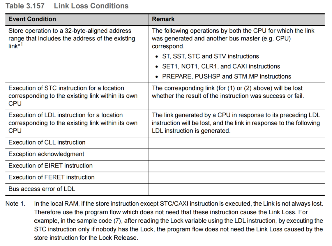
(6) Loss of the link
A link is lost when certain event or address conditions are satisfied. Table 3.157 shows the link loss conditions. A link is lost if any of the conditions shown in this table satisfied.
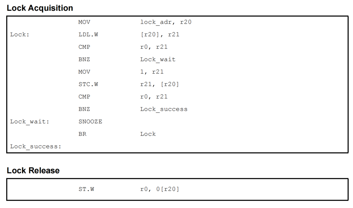
(7) Sample Code
The sample code of a spinlock executed by using the LDL.W and STC.W instructions is shown below.
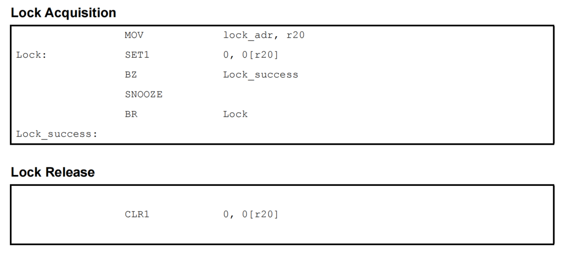
2.3 Performing Mutual Exclusion by Using the SET1 Instruction
The SET1 instruction can be used to perform mutual exclusion over multiple data arrays. By executing the SET1 instruction on the same bit in the memory and then checking the PSW.Z flag, which indicates the execution result, it can be determined whether lock acquisition succeeded or failed.
(1) Sample Code
The sample code of a spinlock executed by using the SET1 instruction is shown below.
2.4 Performing Mutual Exclusion by Using the CAXI Instruction
The CAXI instruction can be used to perform mutual exclusion over multiple data arrays. By executing the CAXI instruction on the same word in the memory and then checking the destination register, it can be determined whether lock acquisition succeeded or failed.
(1) Sample Code
The sample code of a spinlock executed by using the CAXI instruction is shown below.
