0,硬件原理图
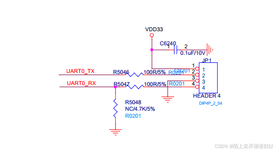
1,确认串口使用uart0
/*
 * UART
 */
#define UART0_IOBASE		0xb8147000	/* Uart0 register base address mapping  */
#define UART0_FREQ		(100000000) /* Serial Clock */ // 100MHz
//#define UART0_FREQ		(CONFIG_OCP_CLOCK_FREQ/8)	/* Serial Clock */ // V6, switch
//#define UART0_FREQ		(CONFIG_OCP_CLOCK_FREQ*12/10)	/* Serial Clock */ // V6, usb otg
//#define UART0_FREQ		6250000 //(CONFIG_OCP_CLOCK_FREQ/4)	/* Serial Clock */ // V7
//#define UART0_FREQ		(CONFIG_OCP_CLOCK_FREQ/4)	/* Serial Clock */ // V7

/* Register offset from UARTx_IOBASE */
#ifdef CONFIG_RTL_8197F_VG
#define UART_RBR                0x00
#define UART_THR                0x00
#else
//#define UART_RBR		0x00
#define UART_RBR		0x24
//#define UART_THR		0x00
#define UART_THR		0x24
#endif
#define UART_IER		0x04
#define UART_IIR		0x08
#define UART_FCR		0x08
#define UART_LCR		0x0C
#define UART_LSR		0x14
#define UART_DLL		0x00
#define UART_DLH		0x04

/* uart LCR register bits */
#define UART_LCR_PEN		0x00000008	/* parity enable bit */
#define UART_LCR_EPS		0X00000010
#define UART_LCR_PARITY		(UART_LCR_PEN | UART_LCR_EPS)
#define UART_LCR_STOP		0x00000004	/* stop bit          */
#define UART_LCR_DLS		0x00000003	/* 8 bits mode       */
#define UART_LCR_DLAB		0x00000080	/* DLAB bit          */


/* Uart baudrate */
#define UART_BAUD_RATEL		(UART_BAUD_DEFAULT & 0x00ff)
#define UART_BAUD_RATEH		((UART_BAUD_DEFAULT & 0xff00) >> 8)
#define UART_IOBASE		UART0_IOBASE

/******************************************************************************
*
* dwc_serial_init - initialize a channel
*
* This routine initializes the number of data bits, parity
* and set the selected baud rate. Interrupts are disabled.
* Set the modem control signals if the option is selected.
*
* RETURNS: N/A
*/

static int dwc_serial_init (void)
{
	REG32(UART_IOBASE+UART_IER) = 0;

	REG32(UART_IOBASE+UART_LCR) = UART_LCR_DLAB;
	REG32(UART_IOBASE+UART_DLL) = UART_BAUD_RATEL;
	REG32(UART_IOBASE+UART_DLH) = UART_BAUD_RATEH;
//REG32(UART_IOBASE+0x1C) = 0xA0030; // 57600, 115200
//REG32(UART_IOBASE+0x20) = 0xC0; // 57600, 115200
	REG32(UART_IOBASE+UART_LCR) = UART_LCR_DLS;
	return 0;
}
2,手动测试串口使用情况
手动写A/B/C进行测试
8197F# mw 0xb8147000 0x41
A8197F# mw 0xb8147000 0x42
B8197F# mw 0xb8147000 0x47
G8197F#
测试代码
#include "asm/stack_asm.h"

/*
 * 调试开关:定义 DEBUG_UART 可启用调试打印
 */
#define DEBUG_UART

#ifdef DEBUG_UART
/* UART 硬件地址(根据实测,THR 在偏移 0x00) */
#define UART_BASE       0xb8147000
#define UART_LSR_OFF    0x14
#define UART_THR_OFF    0x00

/* 发送一个立即数字符 */
.macro  uart_send_char_imm ch
    li      t0, UART_BASE
    li      t1, \ch
1:
    lw      t2, UART_LSR_OFF(t0)
    andi    t2, t2, 0x20        /* THRE 位 */
    beqz    t2, 1b
    nop
    sw      t1, UART_THR_OFF(t0)
.endm

/* 发送字符串(字符串标签) */
.macro  uart_send_str str
    la      t1, \str
1:
    lb      t2, 0(t1)
    beqz    t2, 2f
    nop
    uart_send_char_imm t2       /* 注意:这里直接使用立即数宏,但 t2 是寄存器,不能这样用! */
    addiu   t1, t1, 1
    b       1b
    nop
2:
.endm

.section .rodata
debug_str1:
    .asciz "test@OsStartToRun\r\n"
#endif /* DEBUG_UART */

    .section ".text", "ax"
    .set noreorder
    .global OsStartToRun
    .global OsTaskSchedule

/*
 * VOID OsStartToRun(LosTaskCB * topTask)
 */
OsStartToRun:
#ifdef DEBUG_UART
    /* 直接打印固定字符串 */
    la      t1, debug_str1
1:
    lb      t2, 0(t1)
    beqz    t2, 2f
    nop
    /* 发送字符 */
    li      t0, UART_BASE
3:
    lw      t3, UART_LSR_OFF(t0)
    andi    t3, t3, 0x20
    beqz    t3, 3b
    nop
    sw      t2, UART_THR_OFF(t0)
    addiu   t1, t1, 1
    b       1b
    nop
2:
#endif

    /* 原有代码 */
    lw      sp, 0(a0)
    RESTORE_ALL
    eret
    nop
可以看到有串口打印test@OsStartToRun