【 声明:版权所有,欢迎转载,请勿用于商业用途。 联系信箱:feixiaoxing @163.com】
虽然现在stm32用的很多,很多国产的mcu不是很贵,但是他们和8051比较,还是有一点价格的差异。这一点,如果量不大的情况下,可能不是很在乎。但是产品量比较大的话,其实就非常可观了。所以,对于gpio/uart/pwm/ad/da/时钟中断这类简单应用,很多时候,我们都会选择8051单片机进行开发,价格甚至可以降到几毛钱。不管是工具选择,还是使用过程,都非常方便。当然,如果是8266 wifi+单片机,也是常规的做法。
1、8051编译器
8051的编译器也是keil,一般是推荐先安装51版本的keil,再安装arm版本的keil。两者工程不一样,前者是uvproj,后者是uvprojx。实在安装顺序反了,也没有关系,我们可以通过自己编写bat来编译。
https://www.keil.com/download/product/2、自己准备编译bat文件
如果实在ide弄不出来,其实也没关系,写一个bat也是可以自己编译的,比如这里的run.bat,
@echo off
SET PATH=%PATH%;E:\Keil_v5\C51\BIN
SET C51INC=E:\Keil_v5\C51\INC
SET C51LIB=E:\Keil_v5\C51\LIB

del *.OBJ *.hex *.lst *.m51 2>nul
C51 main.c
A51 STARTUP.A51
BL51 main.OBJ, STARTUP.OBJ TO main
OH51 main
pause
编译过程需要STARTUP.A51,还有一个main.c。其中main.c自己写,而STARTUP.A51可以在安装的keil c51目录找一下即可。找不到的话,这里拷贝改一下名字也行,
$NOMOD51
;------------------------------------------------------------------------------
;  This file is part of the C51 Compiler package
;  Copyright (c) 1988-2005 Keil Elektronik GmbH and Keil Software, Inc.
;  Version 8.01
;
;  *** <<< Use Configuration Wizard in Context Menu >>> ***
;------------------------------------------------------------------------------
;  STARTUP.A51:  This code is executed after processor reset.
;
;  To translate this file use A51 with the following invocation:
;
;     A51 STARTUP.A51
;
;  To link the modified STARTUP.OBJ file to your application use the following
;  Lx51 invocation:
;
;     Lx51 your object file list, STARTUP.OBJ  controls
;
;------------------------------------------------------------------------------
;
;  User-defined <h> Power-On Initialization of Memory
;
;  With the following EQU statements the initialization of memory
;  at processor reset can be defined:
;
; <o> IDATALEN: IDATA memory size <0x0-0x100>
;     <i> Note: The absolute start-address of IDATA memory is always 0
;     <i>       The IDATA space overlaps physically the DATA and BIT areas.
IDATALEN        EQU     80H
;
; <o> XDATASTART: XDATA memory start address <0x0-0xFFFF>
;     <i> The absolute start address of XDATA memory
XDATASTART      EQU     0
;
; <o> XDATALEN: XDATA memory size <0x0-0xFFFF>
;     <i> The length of XDATA memory in bytes.
XDATALEN        EQU     0
;
; <o> PDATASTART: PDATA memory start address <0x0-0xFFFF>
;     <i> The absolute start address of PDATA memory
PDATASTART      EQU     0H
;
; <o> PDATALEN: PDATA memory size <0x0-0xFF>
;     <i> The length of PDATA memory in bytes.
PDATALEN        EQU     0H
;
;</h>
;------------------------------------------------------------------------------
;
;<h> Reentrant Stack Initialization
;
;  The following EQU statements define the stack pointer for reentrant
;  functions and initialized it:
;
; <h> Stack Space for reentrant functions in the SMALL model.
;  <q> IBPSTACK: Enable SMALL model reentrant stack
;     <i> Stack space for reentrant functions in the SMALL model.
IBPSTACK        EQU     0       ; set to 1 if small reentrant is used.
;  <o> IBPSTACKTOP: End address of SMALL model stack <0x0-0xFF>
;     <i> Set the top of the stack to the highest location.
IBPSTACKTOP     EQU     0xFF +1     ; default 0FFH+1
; </h>
;
; <h> Stack Space for reentrant functions in the LARGE model.
;  <q> XBPSTACK: Enable LARGE model reentrant stack
;     <i> Stack space for reentrant functions in the LARGE model.
XBPSTACK        EQU     0       ; set to 1 if large reentrant is used.
;  <o> XBPSTACKTOP: End address of LARGE model stack <0x0-0xFFFF>
;     <i> Set the top of the stack to the highest location.
XBPSTACKTOP     EQU     0xFFFF +1   ; default 0FFFFH+1
; </h>
;
; <h> Stack Space for reentrant functions in the COMPACT model.
;  <q> PBPSTACK: Enable COMPACT model reentrant stack
;     <i> Stack space for reentrant functions in the COMPACT model.
PBPSTACK        EQU     0       ; set to 1 if compact reentrant is used.
;
;   <o> PBPSTACKTOP: End address of COMPACT model stack <0x0-0xFFFF>
;     <i> Set the top of the stack to the highest location.
PBPSTACKTOP     EQU     0xFF +1     ; default 0FFH+1
; </h>
;</h>
;------------------------------------------------------------------------------
;
;  Memory Page for Using the Compact Model with 64 KByte xdata RAM
;  <e>Compact Model Page Definition
;
;  <i>Define the XDATA page used for PDATA variables.
;  <i>PPAGE must conform with the PPAGE set in the linker invocation.
;
; Enable pdata memory page initalization
PPAGEENABLE     EQU     0       ; set to 1 if pdata object are used.
;
; <o> PPAGE number <0x0-0xFF>
; <i> uppermost 256-byte address of the page used for PDATA variables.
PPAGE           EQU     0
;
; <o> SFR address which supplies uppermost address byte <0x0-0xFF>
; <i> most 8051 variants use P2 as uppermost address byte
PPAGE_SFR       DATA    0A0H
;
; </e>
;------------------------------------------------------------------------------

; Standard SFR Symbols
ACC     DATA    0E0H
B       DATA    0F0H
SP      DATA    81H
DPL     DATA    82H
DPH     DATA    83H

                NAME    ?C_STARTUP


?C_C51STARTUP   SEGMENT   CODE
?STACK          SEGMENT   IDATA

                RSEG    ?STACK
                DS      1

                EXTRN CODE (?C_START)
                PUBLIC  ?C_STARTUP

                CSEG    AT      0
?C_STARTUP:     LJMP    STARTUP1

                RSEG    ?C_C51STARTUP

STARTUP1:

IF IDATALEN <> 0
                MOV     R0,#IDATALEN - 1
                CLR     A
IDATALOOP:      MOV     @R0,A
                DJNZ    R0,IDATALOOP
ENDIF

IF XDATALEN <> 0
                MOV     DPTR,#XDATASTART
                MOV     R7,#LOW (XDATALEN)
  IF (LOW (XDATALEN)) <> 0
                MOV     R6,#(HIGH (XDATALEN)) +1
  ELSE
                MOV     R6,#HIGH (XDATALEN)
  ENDIF
                CLR     A
XDATALOOP:      MOVX    @DPTR,A
                INC     DPTR
                DJNZ    R7,XDATALOOP
                DJNZ    R6,XDATALOOP
ENDIF

IF PPAGEENABLE <> 0
                MOV     PPAGE_SFR,#PPAGE
ENDIF

IF PDATALEN <> 0
                MOV     R0,#LOW (PDATASTART)
                MOV     R7,#LOW (PDATALEN)
                CLR     A
PDATALOOP:      MOVX    @R0,A
                INC     R0
                DJNZ    R7,PDATALOOP
ENDIF

IF IBPSTACK <> 0
EXTRN DATA (?C_IBP)

                MOV     ?C_IBP,#LOW IBPSTACKTOP
ENDIF

IF XBPSTACK <> 0
EXTRN DATA (?C_XBP)

                MOV     ?C_XBP,#HIGH XBPSTACKTOP
                MOV     ?C_XBP+1,#LOW XBPSTACKTOP
ENDIF

IF PBPSTACK <> 0
EXTRN DATA (?C_PBP)
                MOV     ?C_PBP,#LOW PBPSTACKTOP
ENDIF

                MOV     SP,#?STACK-1

; This code is required if you use L51_BANK.A51 with Banking Mode 4
;<h> Code Banking
; <q> Select Bank 0 for L51_BANK.A51 Mode 4
#if 0
;     <i> Initialize bank mechanism to code bank 0 when using L51_BANK.A51 with Banking Mode 4.
EXTRN CODE (?B_SWITCH0)
                CALL    ?B_SWITCH0      ; init bank mechanism to code bank 0
#endif
;</h>
                LJMP    ?C_START

                END
3、准备一个main.c
最简单的main.c就是闪灯,
// main.c - STC89C52RC LED
#include <reg52.h>

sbit LED = P2^0;    // LED 接在 P2.0 口(低电平点亮)

void delay_ms(unsigned int ms)
{
    unsigned int i, j;
    for (i = 0; i < ms; i++)
        for (j = 0; j < 123; j++);  // 12MHz 下约 1ms
}

void main(void)
{
    while (1)
    {
        LED = 0;
        delay_ms(100);

        LED = 1;
        delay_ms(100);
    }
}
有了这个main.c,加上之前的STARTUP.A51,这样点击一下bat,就可以编译了。最终的话,可以看到一个hex文件。
4、写一个删除bat脚本
如果出现编译错误,也会生成hex文件。这个时候可以加个pause,看下log。需要删除中间文件,就可以写一个delete.bat,
del  MAIN
del main.hex
del main.LST
del MAIN.M51
del main.OBJ
del STARTUP.LST
del STARTUP.OBJ
5、下载hex文件
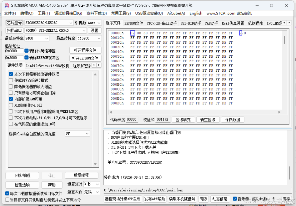
8051基本都是用串口下载,下载的软件是stc-isp。下载的板子都是8051+一个usb转串口。所以我们只需要usb连到pc上面,然后用stc-isp下载即可,本质上就是串口编程。
下载有这么几个步骤,**1)首先需要选中芯片类型,即STC89C52RC/LE52RC,这一步非常重要;**2)其次选中串口;3)选择需要下载的hex文件;4)点击下载/编程;**5)拨动两次单片机上面的开关,一定是拨动开关,不是reset,只有这样才能下载,不然下载不了。**不出意外的话,经过这些步骤,就可以在stc-isp上面看到进度条了。
此时找一个面包板,搭建一下环境,就可以看到led闪烁了。
注1:
当然现在mm32、py32的mcu也很便宜。**对于已经使用51单片机的项目,可以继续使用51单片机。**新项目的话,可以考虑m0 mcu。
注2:
还有一种情况,就是串口通信,这也用得很多。单片的串口一般就是3.0和3.1,其中3.0是接收,3.1是发送。这里用了printf,编译生成的字节会一下子多出来不少,超过1k,之前可能只有几百个字节。这里的串口其实就是烧录的串口。
#include <reg52.h>
#include <stdio.h>      // Required for printf

unsigned int cnt = 0;

void delay_ms(unsigned int ms)
{
    unsigned int i, j;
    for (i = 0; i < ms; i++)
        for (j = 0; j < 125; j++);  // Approximately 1ms at 12MHz
}

void UART_Init(void)
{
    TMOD = 0x20;        // Timer1, mode 2 (8-bit auto-reload)
    TH1 = 0xFD;         // Baud rate 9600 (11.0592MHz crystal)
    TL1 = 0xFD;
    TR1 = 1;            // Start timer1
    SCON = 0x50;        // Serial mode 1 (8-bit UART), enable reception
    TI = 1;             // Set transmit flag to allow printf output
}

void main(void)
{
    UART_Init();
    while (1)
    {
        printf("%d\n", cnt++);   // Output counter value with newline
        delay_ms(10);            // Delay 10ms between outputs
    }
}
注3:
8051的中断和arm mcu比较起来,还是比较简单的,写起来也很容易。这里还有一个好玩的现象,那就是8051的unsigned int是16位,这一点要注意下。
#include <reg52.h>
#include <stdio.h>      // Required for printf

sbit LED = P2^0;

unsigned int cnt = 0;
unsigned int timer_cnt = 0;

void Timer0_ISR(void) interrupt 1
{
    TH0 = 0xFC;         // High 8-bit: 1ms @ 12MHz
    TL0 = 0x18;         // Low 8-bit: 1ms @ 12MHz

    timer_cnt++;
    if (timer_cnt >= 1000)     // 1000ms (1000 * 1ms)
    {
        timer_cnt = 0;
        LED = ~LED;     // Toggle LED
    }
}

void delay_ms(unsigned int ms)
{
    unsigned int i, j;
    for (i = 0; i < ms; i++)
        for (j = 0; j < 125; j++);  // Approximately 1ms at 12MHz
}

void Timer_Init(void)
{
    TMOD &= 0xF0;       // Clear T0 control bits (preserve T1 settings)
    TMOD |= 0x01;       // Set T0 to mode 1 (16-bit timer)

    TH0 = 0xFC;         // Timer for 1ms (12MHz crystal)
    TL0 = 0x18;         // Calculation: 65536 - 1000 = 64536 = 0xFC18

    ET0 = 1;            // Enable timer0 interrupt
    EA  = 1;            // Enable global interrupt
    TR0 = 1;            // Start timer0
}

void UART_Init(void)
{
    TMOD &= 0x0F;       // ✅ Clear T1 control bits (preserve T0 settings)
    TMOD |= 0x20;       // Set T1 to mode 2 (8-bit auto-reload)

    TH1 = 0xFD;         // Baud rate 9600 (11.0592MHz crystal)
    TL1 = 0xFD;
    TR1 = 1;            // Start timer1
    SCON = 0x50;        // Serial mode 1 (8-bit UART), enable reception
    TI = 1;             // Set transmit flag to allow printf output
}

void main(void)
{
    Timer_Init();
    UART_Init();

    while (1)
    {
        printf("%d\n", cnt++);   // Output counter value with newline
        delay_ms(10);            // Delay 10ms between outputs
    }
}
注4:
输入输出交互。最简单的输入,就是按键,记得加一个上拉电阻即可。
#include <reg52.h>

sbit LED = P2^0;      // LED connected to P2.0 (active low)
sbit KEY = P3^2;      // Button connected to P3.2 (INT0 pin, with internal pull-up)

bit led_state = 0;    // LED state: 0=OFF, 1=ON

// Simple debounce delay (about 10ms @ 12MHz)
void delay_ms(unsigned int ms)
{
    unsigned int i, j;
    for (i = 0; i < ms; i++)
        for (j = 0; j < 125; j++);
}

void main(void)
{
    LED = 1;           // Initial OFF (high level turns off)
    led_state = 0;

    while (1)
    {
        if (KEY == 0)           // Button pressed detected (active low)
        {
            delay_ms(10);       // Debounce delay

            if (KEY == 0)       // Confirm the button is actually pressed
            {
                led_state = ~led_state;  // Toggle LED state
                LED = ~led_state;        // Output to LED (Note: LED is active low)

                while (KEY == 0);  // Wait for button release
                delay_ms(5);       // Release debounce
            }
        }
    }
}