接线
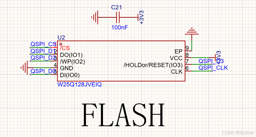
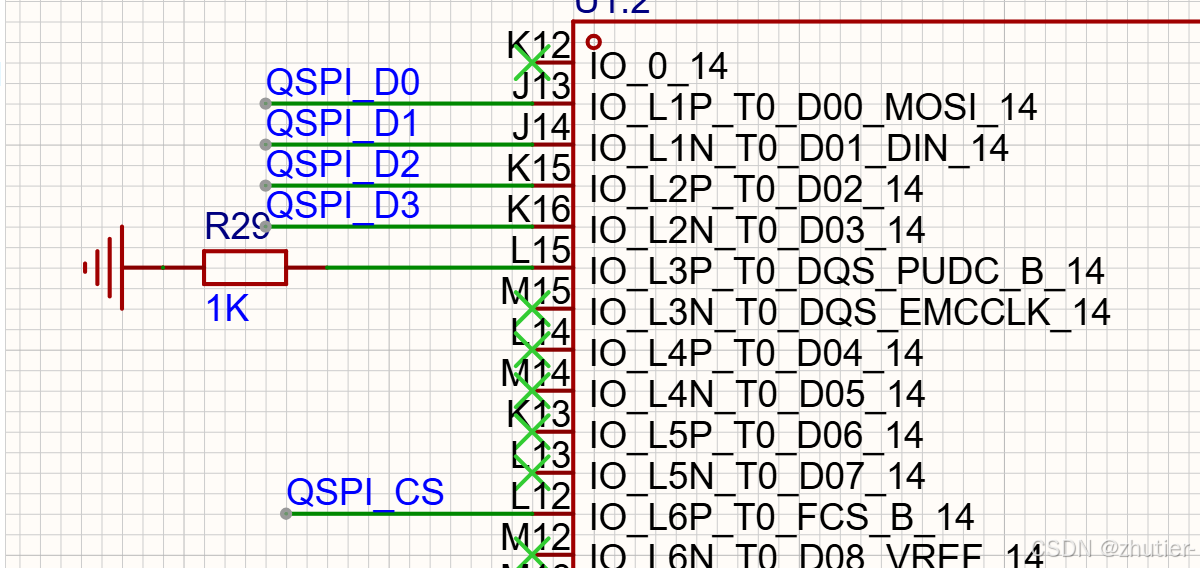
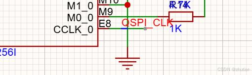
FLASH和FPGA的连接是固定的,所以无需再做引脚的配置。
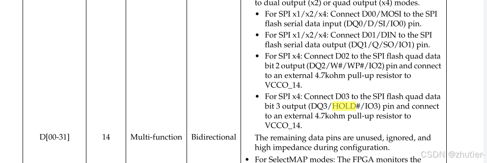
使用的W25Q128JVEIQ 第四个字符Q代表Quad SPI, 可以用SPIx4
连接参考:UG470
写一个简单的LEDblink验证:
`timescale 1ns / 1ps

module Ledblink(
    input sys_clk,
    input rst_n,
    output reg led,
    output wire uart_tx,
    input  wire uart_rx     // 接 CH340 TXD(从电脑接收数据)
    );
reg [31:0] count;


always @(posedge sys_clk or negedge rst_n) begin
    if(!rst_n)
        begin
            count <= 0;
            led <= 0;
        end
    else
        begin
            count <= count + 1;

        if(count == 50000000)
            begin
                led <= ~led;
                count <= 0;
            end
         end
end

endmodule
设置SPI宽度,在.xdc文件里加入:
set_property BITSTREAM.CONFIG.SPI_BUSWIDTH 4 [current_design]生成bit文件后
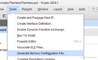
找到Tools-Generate Memory Configuration File
按如下图选择好器件,mcs文件命名,和SPI模式
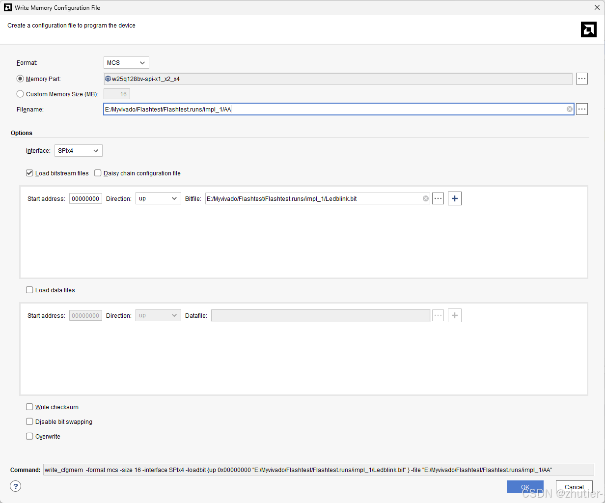
然后即可生成mcs文件