组网需求
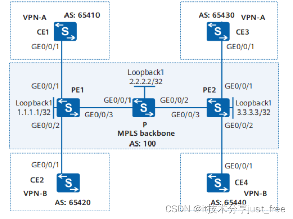
如 图 7-13 , CE1 、 CE3 属于 VPN-A , CE2 、 CE4 属于 VPN-B ; VPN-A 使用的 VPN-target
属性为 111:1 , VPN-B 使用的 VPN-target 属性为 222:2 。不同 VPN 用户之间不能互相访
问。
图 7-13 配置 Dot1q 终结子接口接入 L3VPN 组网图
配置思路
采用如下的思路配置 Dot1q 子接口接入 L3VPN :
- 骨干网中,与 CE 相连的 PE 上需配置 VPN 实例,并把与 CE 相连的接口和相应的 VPN
实例绑定;绑定之后配置与 CE 相连的接口的 IP 地址。 - PE 与 PE 之间配置 OSPF 实现 PE 之间的互通。
- 配置 MPLS 基本能力和 MPLS LDP ,建立 MPLS LSP 。
- 配置 MP-IBGP 交换 VPN 路由信息。
- CE 与 PE 之间配置 EBGP 交换 VPN 路由信息。
- 在 PE 连接 CE 的接口上配置 Dot1q 子接口接入 L3VPN 。
说明
VCMP 的角色是 Client 时,不能配置 VLAN 终结子接口。
操作步骤
步骤 1 在 MPLS 骨干网上配置 IGP 协议,实现骨干网 PE 和 P 的互通
配置 PE1 。
<HUAWEI> system-view
HUAWEI sysname PE1
PE1 router id 1.1.1.1
PE1 interface loopback 1
PE1-LoopBack1 ip address 1.1.1.1 32
PE1-LoopBack1 quit
PE1 vlan batch 30
PE1 interface gigabitethernet 0/0/3
PE1-GigabitEthernet0/0/3 port link-type hybrid
PE1-GigabitEthernet0/0/3 port hybrid pvid vlan 30
PE1-GigabitEthernet0/0/3 port hybrid untagged vlan 30
PE1-GigabitEthernet0/0/3 quit
PE1 interface vlanif 30
PE1-Vlanif30 ip address 7.7.7.7 24
PE1-Vlanif30 quit
PE1 ospf
PE1-ospf-1 area 0
PE1-ospf-1-area-0.0.0.0 network 7.7.7.0 0.0.0.255
PE1-ospf-1-area-0.0.0.0 network 1.1.1.1 0.0.0.0
PE1-ospf-1-area-0.0.0.0 quit
PE1-ospf-1 quit
配置 P 。
<HUAWEI> system-view
HUAWEI sysname P
P router id 2.2.2.2
P interface loopback 1
P-LoopBack1 ip address 2.2.2.2 32
P-LoopBack1 quit
P vlan batch 30 60
P interface gigabitethernet 0/0/1
P-GigabitEthernet0/0/1 port link-type hybrid
P-GigabitEthernet0/0/1 port hybrid pvid vlan 30
P-GigabitEthernet0/0/1 port hybrid untagged vlan 30
P-GigabitEthernet0/0/1 quit
P interface gigabitethernet 0/0/2
P-GigabitEthernet0/0/2 port link-type hybrid
P-GigabitEthernet0/0/2 port hybrid pvid vlan 60
P-GigabitEthernet0/0/2 port hybrid untagged vlan 60
P-GigabitEthernet0/0/2 quit
P interface vlanif 30
P-Vlanif30 ip address 7.7.7.8 24
P-Vlanif30 quit
P interface vlanif 60
P-Vlanif60 ip address 6.6.6.6 24
P-Vlanif60 quit
P ospf
P-ospf-1 area 0
P-ospf-1-area-0.0.0.0 network 7.7.7.0 0.0.0.255
P-ospf-1-area-0.0.0.0 network 6.6.6.0 0.0.0.255
P-ospf-1-area-0.0.0.0 network 2.2.2.2 0.0.0.0
P-ospf-1-area-0.0.0.0 quit
P-ospf-1 quit
配置 PE2 。
<HUAWEI> system-view
HUAWEI sysname PE2
PE2 router id 3.3.3.3
PE2 interface loopback 1
PE2-LoopBack1 ip address 3.3.3.3 32
PE2-LoopBack1 quit
PE2 vlan batch 60
PE2 interface gigabitethernet 0/0/3
PE2-GigabitEthernet0/0/3 port link-type hybrid
PE2-GigabitEthernet0/0/3 port hybrid pvid vlan 60
PE2-GigabitEthernet0/0/3 port hybrid untagged vlan 60
PE2-GigabitEthernet0/0/3 quit
PE2 interface vlanif 60
PE2-Vlanif60 ip address 6.6.6.7 24
PE2-Vlanif60 quit
PE2 ospf
PE2-ospf-1 area 0
PE2-ospf-1-area-0.0.0.0 network 6.6.6.0 0.0.0.255
PE2-ospf-1-area-0.0.0.0 network 3.3.3.3 0.0.0.0
PE2-ospf-1-area-0.0.0.0 quit
PE2-ospf-1 quit
配置完成后, PE1 和 P 、 P 和 PE2 之间应能建立 OSPF 邻居关系,执行 display ospf peer
命令可以看到邻居状态为 Full 。执行 display ip routing-table 命令可以看到 PE 之间学
习到对方的 Loopback1 路由。
以 PE1 的显示为例:
PE1 display ip routing-table
Route Flags: R - relay, D - download to fibȀ T - to vpn-instance
Routing Tables: Public
Destinations : 8 Routes : 8
Destination/Mask Proto Pre Cost Flags NextHop Interface
1.1.1.1/32 Direct 0 0 D 127.0.0.1 LoopBack1
2.2.2.2/32 OSPF 10 1 D 7.7.7.8 Vlanif30
3.3.3.3/32 OSPF 10 2 D 7.7.7.8 Vlanif30
6.6.6.0/24 OSPF 10 2 D 7.7.7.8 Vlanif30
7.7.7.0/24 Direct 0 0 D 7.7.7.7 Vlanif30
7.7.7.7/32 Direct 0 0 D 127.0.0.1 Vlanif30
127.0.0.0/8 Direct 0 0 D 127.0.0.1 InLoopBack0
127.0.0.1/32 Direct 0 0 D 127.0.0.1 InLoopBack0
PE1 display ospf peer
OSPF Process 1 with Router ID 1.1.1.1
Neighbors
Area 0.0.0.0 interface 7.7.7.7(Vlanif30)'s neighbors
Router ID: 2.2.2.2 Address: 7.7.7.8
State: Full Mode:Nbr is Master Priority: 1
DR: 7.7.7.8 BDR: 7.7.7.7 MTU: 0
Dead timer due in 37 sec
Retrans timer interval: 5
Neighbor is up for 00:00:20
Authentication Sequence: 0
步骤 2 在 MPLS 骨干网上配置 MPLS 基本能力和 MPLS LDP ,建立 LDP LSP
配置 PE1 。
PE1 mpls lsr-id 1.1.1.1
PE1 mpls
PE1-mpls quit
PE1 mpls ldp
PE1-mpls-ldp quit
PE1 interface vlanif 30
PE1-Vlanif30 mpls
PE1-Vlanif30 mpls ldp
PE1-Vlanif30 quit
配置 P 。
P mpls lsr-id 2.2.2.2
P mpls
P-mpls quit
P mpls ldp
P-mpls-ldp quit
P interface vlanif 30
P-Vlanif30 mpls
P-Vlanif30 mpls ldp
P-Vlanif30 quit
P interface vlanif 60
P-Vlanif60 mpls
P-Vlanif60 mpls ldp
P-Vlanif60 quit
配置 PE2 。
PE2 mpls lsr-id 3.3.3.3
PE2 mpls
PE2-mpls quit
PE2 mpls ldp
PE2-mpls-ldp quit
PE2 interface vlanif 60
PE2-Vlanif60 mpls
PE2-Vlanif60 mpls ldp
PE2-Vlanif60 quit
上述配置完成后, PE1 与 P 、 P 与 PE2 之间应能建立 LDP 会话,执行 display mpls ldp
session 命令可以看到显示结果中 Status 项为" Operational "。执行 display mpls ldp
lsp 命令,可以看到 LDP LSP 的建立情况。
以 PE1 的显示为例:
PE1 display mpls ldp session
LDP Session(s) in Public Network
Codes: LAM(Label Advertisement Mode), SsnAge Unit(DDDD:HH:MM)
A '*' before a session means the session is being deleted.
PeerID Status LAM SsnRole SsnAge KASent/Rcv
2.2.2.2:0 Operational DU Passive 0000:15:29 3717/3717
TOTAL: 1 session(s) Found.
PE1 display mpls ldp lsp
LDP LSP Information
Flag after Out IF: (I) - LSP Is Only Iterated by RLFA
DestAddress/Mask In/OutLabel UpstreamPeer NextHop OutInterface
1.1.1.1/32 3/NULL 2.2.2.2 127.0.0.1 InLoop0
*1.1.1.1/32 Liberal/1024 DS/2.2.2.2
2.2.2.2/32 NULL/3 - 7.7.7.8 Vlanif30
2.2.2.2/32 1024/3 2.2.2.2 7.7.7.8 Vlanif30
3.3.3.3/32 NULL/1025 - 7.7.7.8 Vlanif30
3.3.3.3/32 1025/1025 2.2.2.2 7.7.7.8 Vlanif30
TOTAL: 5 Normal LSP(s) Found.
TOTAL: 1 Liberal LSP(s) Found.
TOTAL: 0 Frr LSP(s) Found.
A '*' before an LSP means the LSP is not established
A '*' before a Label means the USCB or DSCB is stale
A '*' before a UpstreamPeer means the session is stale
A '*' before a DS means the session is stale
A '*' before a NextHop means the LSP is FRR LSP
步骤 3 在 PE 设备上配置 VPN 实例,将 CE 接入 PE
配置 PE1 。
PE1 ip vpn-instance vpna
PE1-vpn-instance-vpna route-distinguisher 100:1
PE1-vpn-instance-vpna-af-ipv4 vpn-target 111:1 both
PE1-vpn-instance-vpna-af-ipv4 quit
PE1-vpn-instance-vpna quit
PE1 ip vpn-instance vpnb
PE1-vpn-instance-vpnb route-distinguisher 100:2
PE1-vpn-instance-vpnb-af-ipv4 vpn-target 222:2 both
PE1-vpn-instance-vpnb-af-ipv4 quit
PE1-vpn-instance-vpnb quit
PE1 vcmp role silent
PE1 interface gigabitethernet 0/0/1
PE1-GigabitEthernet0/0/1 port link-type hybrid
PE1-GigabitEthernet0/0/1 quit
PE1 interface gigabitethernet 0/0/1.1
PE1-GigabitEthernet0/0/1.1 dot1q termination vid 10
PE1-GigabitEthernet0/0/1.1 ip binding vpn-instance vpna
PE1-GigabitEthernet0/0/1.1 ip address 10.1.1.2 24
PE1-GigabitEthernet0/0/1.1 arp broadcast enable
PE1-GigabitEthernet0/0/1.1 quit
PE1 interface gigabitethernet 0/0/2
PE1-GigabitEthernet0/0/2 port link-type hybrid
PE1-GigabitEthernet0/0/2 quit
PE1 interface gigabitethernet 0/0/2.1
PE1-GigabitEthernet0/0/2.1 dot1q termination vid 20
PE1-GigabitEthernet0/0/2.1 ip binding vpn-instance vpnb
PE1-GigabitEthernet0/0/2.1 ip address 10.2.1.2 24
PE1-GigabitEthernet0/0/2.1 arp broadcast enable
PE1-GigabitEthernet0/0/2.1 quit
配置 PE2 。
PE2 ip vpn-instance vpna
PE2-vpn-instance-vpna route-distinguisher 200:1
PE2-vpn-instance-vpna-af-ipv4 vpn-target 111:1 both
PE2-vpn-instance-vpna-af-ipv4 quit
PE2-vpn-instance-vpna quit
PE2 ip vpn-instance vpnb
PE2-vpn-instance-vpnb route-distinguisher 200:2
PE2-vpn-instance-vpnb-af-ipv4 vpn-target 222:2 both
PE2-vpn-instance-vpnb-af-ipv4 quit
PE2-vpn-instance-vpnb quit
PE2 vcmp role silent
PE2 interface gigabitethernet 0/0/1
PE2-GigabitEthernet0/0/1 port link-type hybrid
PE2-GigabitEthernet0/0/1 quit
PE2 interface gigabitethernet 0/0/1.1
PE2-GigabitEthernet0/0/1.1 dot1q termination vid 10
PE2-GigabitEthernet0/0/1.1 ip binding vpn-instance vpna
PE2-GigabitEthernet0/0/1.1 ip address 10.3.1.2 24
PE2-GigabitEthernet0/0/1.1 arp broadcast enable
PE2-GigabitEthernet0/0/1.1 quit
PE2 interface gigabitethernet 0/0/2
PE2-GigabitEthernet0/0/2 port link-type hybrid
PE2-GigabitEthernet0/0/2 quit
PE2 interface gigabitethernet 0/0/2.1
PE2-GigabitEthernet0/0/2.1 dot1q termination vid 20
PE2-GigabitEthernet0/0/2.1 ip binding vpn-instance vpnb
PE2-GigabitEthernet0/0/2.1 ip address 10.4.1.2 24
PE2-GigabitEthernet0/0/2.1 arp broadcast enable
PE2-GigabitEthernet0/0/2.1 quit
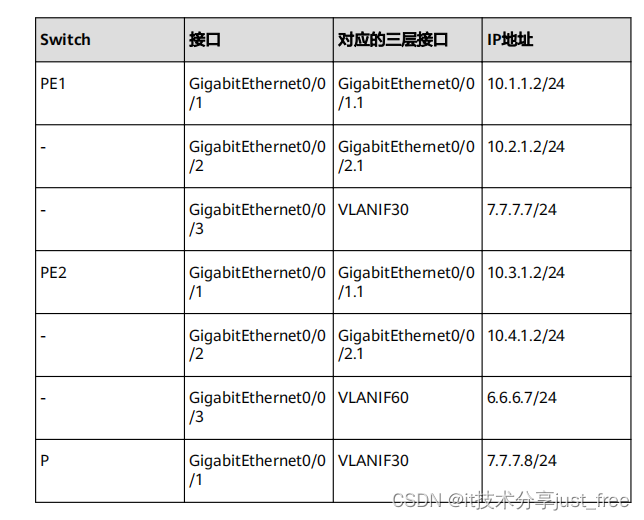
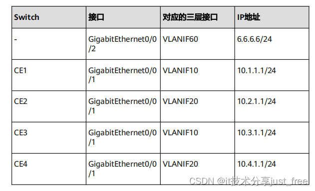
按 图 7-13 配置 CE1 的接口 IP 地址。 CE2 、 CE3 和 CE4 的配置与 CE1 类似,不再赘述。
<HUAWEI> system-view
HUAWEI sysname CE1
CE1 vlan batch 10
CE1 interface gigabitethernet 0/0/1
CE1-GigabitEthernet0/0/1 port link-type hybrid
CE1-GigabitEthernet0/0/1 port hybrid pvid vlan 10
CE1-GigabitEthernet0/0/1 port hybrid tagged vlan 10
CE1-GigabitEthernet0/0/1 quit
CE1 interface vlanif 10
CE1-Vlanif10 ip address 10.1.1.1 24
CE1-Vlanif10 quit
配置完成后,在 PE 设备上执行 display ip vpn-instance verbose 命令可以看到 VPN 实
例的配置情况。各 PE 能 Ping 通自己接入的 CE 。
说明
当 PE 上有多个绑定了同一个 VPN 的接口,则使用 ping -vpn-instance 命令 Ping 对端 PE 接入的 CE
时,要指定源 IP 地址,即要指定 ping -vpn-instance vpn-instance-name -a source-ip-address
dest-ip-address 命令中的参数 -a source-ip-address ,否则可能 Ping 不通。
以 PE1 为例:
PE1 display ip vpn-instance verbose
Total VPN-Instances configured : 2
Total IPv4 VPN-Instances configured : 2
Total IPv6 VPN-Instances configured : 0
VPN-Instance Name and ID : vpna, 1
Interfaces : Gigabitethernet0/0/1.1
Address family ipv4
Create date : 2013-08-28 21:01:00+00:00
Up time : 0 days, 22 hours, 24 minutes and 53 seconds
Route Distinguisher : 100:1
Export VPN Targets : 111:1
Import VPN Targets : 111:1
Label Policy : label per instance
Per-Instance Label : 4098
Log Interval : 5
VPN-Instance Name and ID : vpnb, 2
Interfaces : Gigabitethernet0/0/2.1
Address family ipv4
Create date : 2013-08-28 21:01:00+00:00
Up time : 0 days, 22 hours, 24 minutes and 53 seconds
Route Distinguisher : 100:2
Export VPN Targets : 222:2
Import VPN Targets : 222:2
Label Policy : label per instance
Per-Instance Label : 4099
Log Interval : 5
PE1 ping -vpn-instance vpna 10.1.1.1
PING 10.1.1.1: 56 data bytes, press CTRL_C to break
Reply from 10.1.1.1: bytes=56 Sequence=1 ttl=255 time=5 ms
Reply from 10.1.1.1: bytes=56 Sequence=2 ttl=255 time=3 ms
Reply from 10.1.1.1: bytes=56 Sequence=3 ttl=255 time=3 ms
Reply from 10.1.1.1: bytes=56 Sequence=4 ttl=255 time=3 ms
Reply from 10.1.1.1: bytes=56 Sequence=5 ttl=255 time=16 ms
--- 10.1.1.1 ping statistics ---
5 packet(s) transmitted
5 packet(s) received
0.00% packet loss
round-trip min/avg/max = 3/6/16 ms
步骤 4 在 PE 与 CE 之间建立 EBGP 对等体关系,引入 VPN 路由
配置 CE1 。 CE2 、 CE3 和 CE4 的配置与 CE1 类似,不再赘述。
CE1 bgp 65410
CE1-bgp peer 10.1.1.2 as-number 100
CE1-bgp import-route direct
配置 PE1 。 PE2 的配置与 PE1 类似,不再赘述。
PE1 bgp 100
PE1-bgp ipv4-family vpn-instance vpna
PE1-bgp-vpna peer 10.1.1.1 as-number 65410
PE1-bgp-vpna import-route direct
PE1-bgp-vpna quit
PE1-bgp ipv4-family vpn-instance vpnb
PE1-bgp-vpnb peer 10.2.1.1 as-number 65420
PE1-bgp-vpnb import-route direct
PE1-bgp-vpnb quit
PE1-bgp quit
配置完成后,在 PE 设备上执行 display bgp vpnv4 vpn-instance peer 命令,可以看到
PE 与 CE 之间的 BGP 对等体关系已建立,并达到 Established 状态。
以 PE1 与 CE1 的对等体关系为例:
PE1 display bgp vpnv4 vpn-instance vpna peer
BGP local router ID : 1.1.1.1
Local AS number : 100
VPN-Instance vpna, Router ID 1.1.1.1:
Total number of peers : 1 Peers in established state : 1
Peer V AS MsgRcvd MsgSent OutQ Up/Down State PrefRcv
10.1.1.1 4 65410 11 9 0 00:07:25 Established 1
步骤 5 在 PE 之间建立 MP-IBGP 对等体关系
配置 PE1 。
PE1 bgp 100
PE1-bgp peer 3.3.3.3 as-number 100
PE1-bgp peer 3.3.3.3 connect-interface loopback 1
PE1-bgp ipv4-family vpnv4
PE1-bgp-af-vpnv4 peer 3.3.3.3 enable
PE1-bgp-af-vpnv4 quit
PE1-bgp quit
配置 PE2 。
PE2 bgp 100
PE2-bgp peer 1.1.1.1 as-number 100
PE2-bgp peer 1.1.1.1 connect-interface loopback 1
PE2-bgp ipv4-family vpnv4
PE2-bgp-af-vpnv4 peer 1.1.1.1 enable
PE2-bgp-af-vpnv4 quit
PE2-bgp quit
配置完成后,在 PE 设备上执行 display bgp peer 或 display bgp vpnv4 all peer 命令,
可以看到 PE 之间的 BGP 对等体关系已建立,并达到 Established 状态。
PE1 display bgp peer
BGP local router ID : 1.1.1.1
Local AS number : 100
Total number of peers : 1 Peers in established state : 1
Peer V AS MsgRcvd MsgSent OutQ Up/Down State PrefRcv
3.3.3.3 4 100 12 6 0 00:02:21 Established 0
PE1 display bgp vpnv4 all peer
BGP local router ID : 1.1.1.1
Local AS number : 100
Total number of peers : 3 Peers in established state : 3
Peer V AS MsgRcvd MsgSent OutQ Up/Down State PrefRcv
3.3.3.3 4 100 12 18 0 00:09:38 Established 0
Peer of IPv4-family for vpn instance :
VPN-Instance vpna, Router ID 1.1.1.1:
10.1.1.1 4 65410 25 25 0 00:17:57 Established 1
VPN-Instance vpnb, Router ID 1.1.1.1:
10.2.1.1 4 65420 21 22 0 00:17:10 Established 1
步骤 6 检查配置结果
在 PE 设备上执行 display ip routing-table vpn-instance 命令,可以看到去往对端 CE
的路由。
以 PE1 的显示为例:
PE1 display ip routing-table vpn-instance vpna
Route Flags: R - relay, D - download to fibȀ T - to vpn-instance
Routing Tables: vpna
Destinations : 3 Routes : 3
Destination/Mask Proto Pre Cost Flags NextHop Interface
10.1.1.0/24 Direct 0 0 D 10.1.1.2 Gigabitethernet0/0/1.1
10.1.1.2/32 Direct 0 0 D 127.0.0.1 Gigabitethernet0/0/1.1
10.3.1.0/24 IBGP 255 0 RD 3.3.3.3 Vlanif30
PE1 display ip routing-table vpn-instance vpnb
Route Flags: R - relay, D - download to fibȀ T - to vpn-instance
Routing Tables: vpnb
Destinations : 3 Routes : 3
Destination/Mask Proto Pre Cost Flags NextHop Interface
10.2.1.0/24 Direct 0 0 D 10.2.1.2 Gigabitethernet0/0/2.1
10.2.1.2/32 Direct 0 0 D 127.0.0.1 Gigabitethernet0/0/2.1
10.4.1.0/24 IBGP 255 0 RD 3.3.3.3 Vlanif30
同一 VPN 的 CE 能够相互 Ping 通,不同 VPN 的 CE 不能相互 Ping 通。
例如: CE1 能够 Ping 通 CE3 ( 10.3.1.1 ),但不能 Ping 通 CE4 ( 10.4.1.1 )。
CE1 ping 10.3.1.1
PING 10.3.1.1: 56 data bytes, press CTRL_C to break
Reply from 10.3.1.1: bytes=56 Sequence=1 ttl=253 time=72 ms
Reply from 10.3.1.1: bytes=56 Sequence=2 ttl=253 time=34 ms
Reply from 10.3.1.1: bytes=56 Sequence=3 ttl=253 time=50 ms
Reply from 10.3.1.1: bytes=56 Sequence=4 ttl=253 time=50 ms
Reply from 10.3.1.1: bytes=56 Sequence=5 ttl=253 time=34 ms
--- 10.3.1.1 ping statistics ---
5 packet(s) transmitted
5 packet(s) received
0.00% packet loss
round-trip min/avg/max = 34/48/72 ms
CE1 ping 10.4.1.1
PING 10.4.1.1: 56 data bytes, press CTRL_C to break
Request time out
Request time out
Request time out
Request time out
Request time out
--- 10.4.1.1 ping statistics ---
5 packet(s) transmitted
0 packet(s) received
100.00% packet loss
---- 结束
配置文件
PE1 的配置文件
sysname PE1
router id 1.1.1.1
vlan batch 30
ip vpn-instance vpna
ipv4-family
route-distinguisher 100:1
vpn-target 111:1 export-extcommunity
vpn-target 111:1 import-extcommunity
ip vpn-instance vpnb
ipv4-family
route-distinguisher 100:2
vpn-target 222:2 export-extcommunity
vpn-target 222:2 import-extcommunity
mpls lsr-id 1.1.1.1
mpls
mpls ldp
interface Vlanif30
ip address 7.7.7.7 255.255.255.0
mpls
mpls ldp
interface GigabitEthernet0/0/1
port link-type hybrid
interface GigabitEthernet0/0/1.1
dot1q termination vid 10
ip binding vpn-instance vpna
ip address 10.1.1.2 255.255.255.0
arp broadcast enable
interface GigabitEthernet0/0/2
port link-type hybrid
interface GigabitEthernet0/0/2.1
dot1q termination vid 20
ip binding vpn-instance vpnb
ip address 10.2.1.2 255.255.255.0
arp broadcast enable
interface GigabitEthernet0/0/3
port link-type hybrid
port hybrid pvid vlan 30
port hybrid untagged vlan 30
interface LoopBack1
ip address 1.1.1.1 255.255.255.255
bgp 100
peer 3.3.3.3 as-number 100
peer 3.3.3.3 connect-interface LoopBack1
ipv4-family unicast
undo synchronization
peer 3.3.3.3 enable
ipv4-family vpnv4
policy vpn-target
peer 3.3.3.3 enable
ipv4-family vpn-instance vpna
import-route direct
peer 10.1.1.1 as-number 65410
ipv4-family vpn-instance vpnb
import-route direct
peer 10.2.1.1 as-number 65420
ospf 1
area 0.0.0.0
network 1.1.1.1 0.0.0.0
network 7.7.7.0 0.0.0.255
return
● P 的配置文件
sysname P
router id 2.2.2.2
vlan batch 30 60
mpls lsr-id 2.2.2.2
mpls
mpls ldp
interface Vlanif30
ip address 7.7.7.8 255.255.255.0
mpls
mpls ldp
interface Vlanif60
ip address 6.6.6.6 255.255.255.0
mpls
mpls ldp
interface GigabitEthernet0/0/1
port link-type hybrid
port hybrid pvid vlan 30
port hybrid untagged vlan 30
interface GigabitEthernet0/0/2
port link-type hybrid
port hybrid pvid vlan 60
port hybrid untagged vlan 60
interface LoopBack1
ip address 2.2.2.2 255.255.255.255
ospf 1
area 0.0.0.0
network 2.2.2.2 0.0.0.0
network 6.6.6.0 0.0.0.255
network 7.7.7.0 0.0.0.255
return
● PE2 的配置文件
sysname PE2
router id 3.3.3.3
vlan batch 60
ip vpn-instance vpna
ipv4-family
route-distinguisher 200:1
vpn-target 111:1 export-extcommunity
vpn-target 111:1 import-extcommunity
ip vpn-instance vpnb
ipv4-family
route-distinguisher 200:2
vpn-target 222:2 export-extcommunity
vpn-target 222:2 import-extcommunity
mpls lsr-id 3.3.3.3
mpls
mpls ldp
interface Vlanif60
ip address 6.6.6.7 255.255.255.0
mpls
mpls ldp
interface GigabitEthernet0/0/1
port link-type hybrid
interface GigabitEthernet0/0/1.1
dot1q termination vid 10
ip binding vpn-instance vpna
ip address 10.3.1.2 255.255.255.0
arp broadcast enable
interface GigabitEthernet0/0/2
port link-type hybrid
interface GigabitEthernet0/0/2.1
dot1q termination vid 20
ip binding vpn-instance vpnb
ip address 10.4.1.2 255.255.255.0
arp broadcast enable
interface GigabitEthernet0/0/3
port link-type hybrid
port hybrid pvid vlan 60
port hybrid untagged vlan 60
interface LoopBack1
ip address 3.3.3.3 255.255.255.255
bgp 100
peer 1.1.1.1 as-number 100
peer 1.1.1.1 connect-interface LoopBack1
ipv4-family unicast
undo synchronization
peer 1.1.1.1 enable
ipv4-family vpnv4
policy vpn-target
peer 1.1.1.1 enable
ipv4-family vpn-instance vpna
import-route direct
peer 10.3.1.1 as-number 65430
ipv4-family vpn-instance vpnb
import-route direct
peer 10.4.1.1 as-number 65440
ospf 1
area 0.0.0.0
network 3.3.3.3 0.0.0.0
network 6.6.6.0 0.0.0.255
return
CE1 的配置文件
sysname CE1
vlan batch 10
interface Vlanif10
ip address 10.1.1.1 255.255.255.0
interface GigabitEthernet0/0/1
port link-type hybrid
port hybrid pvid vlan 10
port hybrid tagged vlan 10
bgp 65410
peer 10.1.1.2 as-number 100
ipv4-family unicast
undo synchronization
import-route direct
peer 10.1.1.2 enable
return
● CE2 的配置文件
sysname CE2
vlan batch 20
interface Vlanif20
ip address 10.2.1.1 255.255.255.0
interface GigabitEthernet0/0/1
port link-type hybrid
port hybrid pvid vlan 20
port hybrid tagged vlan 20
bgp 65420
peer 10.2.1.2 as-number 100
ipv4-family unicast
undo synchronization
import-route direct
peer 10.2.1.2 enable
return
● CE3 的配置文件
sysname CE3
vlan batch 10
interface Vlanif10
ip address 10.3.1.1 255.255.255.0
interface GigabitEthernet0/0/1
port link-type hybrid
port hybrid pvid vlan 10
port hybrid tagged vlan 10
bgp 65430
peer 10.3.1.2 as-number 100
ipv4-family unicast
undo synchronization
import-route direct
peer 10.3.1.2 enable
return
● CE4 的配置文件
sysname CE4
vlan batch 20
interface Vlanif20
ip address 10.4.1.1 255.255.255.0
interface GigabitEthernet0/0/1
port link-type hybrid
port hybrid pvid vlan 20
port hybrid tagged vlan 20
bgp 65440
peer 10.4.1.2 as-number 100
ipv4-family unicast
undo synchronization
import-route direct
peer 10.4.1.2 enable
return