作者:Matthew Yu
来自:Fab academy
在数字化时代的浪潮中,柴火创客空间作为创新与实践的摇篮,不仅为Fab Academy 2024的学员们提供了一个充满活力的学习和创作环境,更是将科技的力量与人文关怀深度融合。今天,我们自豪地介绍柴火创客空间辅导毕业的其中一位学员Matthew Yu的终极项目------Mr.M,一个集成了大型语言模型(LLM)的本地个人助理。其独特的设计理念和强大的功能,重新定义了我们与智能设备之间的互动。让我们深入了解Mr. M的诞生历程!
项目介绍
项目概述
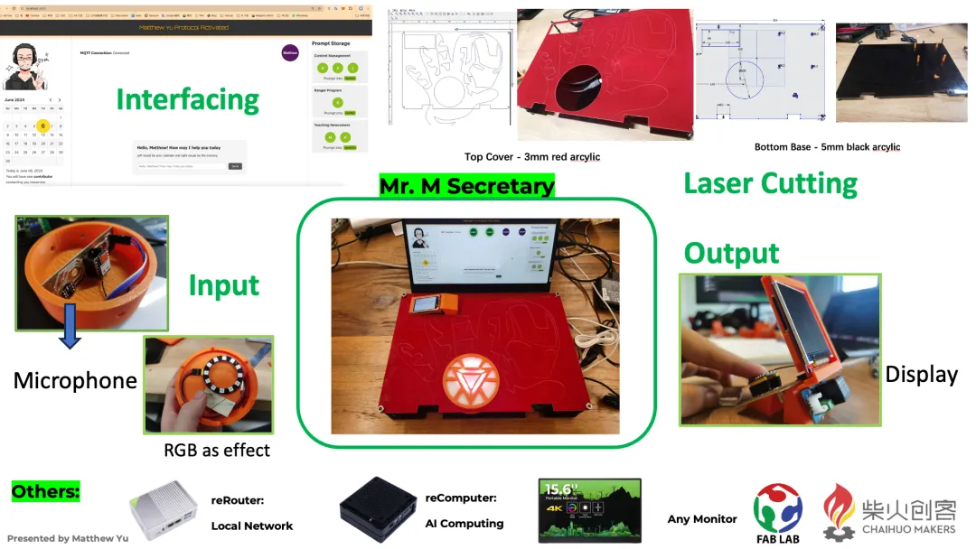
Mr.M基本工作:
-
它将在同一个 Wi-Fi 上接收来自 INMP441 和 XIAO ESP32C3 移动模块的音频消息(音频到波浪文件)。
-
然后它会将音频转换为单词(文本)并尝试理解它:对于已经提示的任务,将自动生成日历信息(JSX文件)。
-
相应的日历消息或一些也被提示的信息将通过MQTT发送到另一个移动模块,与ILI9341显示屏一起显示。
功能模块介绍
麦克风输入:

这个输入可能看起来不太好,这是它的具体结构:
PCB可以很好地贴合3D打印部件,但像左边一样,添加卡住柱子令人更加放心。
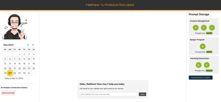
显示输出:

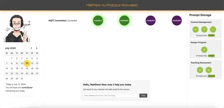
UI操作图像(我真的为此感到非常自豪):
材料清单
|--------------------------------------------------------|----|
| 原件 | 数量 |
| reComputer J4012 | x1 |
| reRouter | x1 |
| Monitor | x1 |
| XIAO ESP32C3 | x2 |
| INMP441 | x1 |
| 3 Pin Header SMD | x2 |
| Grove Female Header | x1 |
| ILI9341 | x1 |
| Grove RGB LED Ring | x1 |
| Power Supply Extension | x1 |
| Network Cable | x1 |
| Type-C Male Connector to Three Type-C Female Connector | x1 |
| M5*60 screw | x4 |
| M5 nut | x8 |
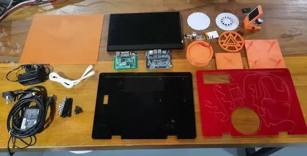
以下是材料总览:
微控制器接口与编程
首先是我的软件测试部分:
(输入)移动模块 - 原始音频数据到 WAV 文件:
功能:为电路板通电,它将记录并生成WAV文件并传输到服务器,其中IP由网络提供。
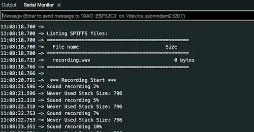
reComputer 可以读取 IP 并从临时服务器下载文件。
相关参考:(input) Mobile Module - Raw Audio Data to Words | Matthew's FabLab Journey (fabacademy.org)
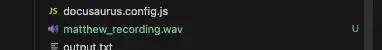
WAV文件转文本 reComputer:
将WAV文件转换为文本,并将文本输入到LLM(Ollama API)中:
-
WAV 文件位于显示器的右上角。
-
左下角是交互式页面(docusaurus pages)运行的地方
-
左上角是下载音频文件的地方
相关参考:(input) Mobile Module - Raw Audio Data to Words | Matthew's FabLab Journey (fabacademy.org)
为了实现这部分,我需要在我的 reComputer 上设置一个 LLM 驱动的机器人:

有关聊天机器人的更多详细信息:Chat Bot(Local Server) | Matthew's FabLab Journey
为了让这个机器人看起来更好,我使用 GPT 本身来生成代码。
有关UI操作页面设置的更多信息:Operating UI Setting | Matthew's FabLab Journey
音频文本到设计的日历标准(JSX):
我需要能够将我的单词(音频文本文件)翻译成docusaurus平台可以渲染的日历JSX标准文件:
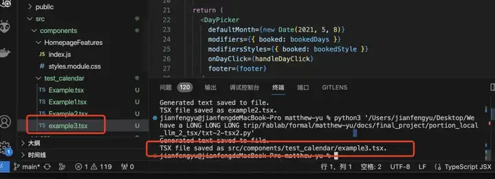
!注意:代码目前正在MAC上进行测试。但是 reComputer 和 MAC 都共享 Linux,因此代码是共享的。
有关本地LLM和自动生成tsx文件的更多信息:Local LLM and Auto-generation tsx file | Matthew's FabLab Journey (fabacademy.org)
为了正确使用 LLM,我需要使用 Prompt Enginner 很好地学习和应用:

有关提示设置的更多详细信息:Prompt Setup | Matthew's FabLab Journey (fabacademy.org)
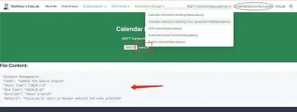
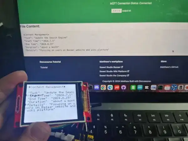
(输出)移动模块 - 接收和显示日历信:
在reComputer生成标准JSX日历文件后,从处理后的文本文件。我将把消息从文本文件传输到移动模块并显示它,同时还可以控制一些东西。

有关移动模块的更多详细信息 -接受和显示日历信息:(Output) Mobile Module - Receive and Display Calendar Information | Matthew's FabLab Journey
!注意:为了应用此功能,它需要 MQTT 函数,我已经在 reComputer 中应用,让它充当代理进行运行。

有关MQTT连接XIAO板子和Docusaurus-website的更多详细信息:MQTT connect with XIAO boards and Docusaurus-website | Matthew's FabLab Journey (fabacademy.org)
同时需要使用Docusaurus页面在network(reRouter)下构建和实现MQTT功能:
接口:
我使用我的作业网站页面设计机器人,并将所有无线功能放在一起。这些可以自动完成。
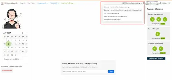
!注意:
自动化操作对于用户来说十分方便,但他们也可以在FAB Academy MQTT(MQTT broker (#18) · 议题 · Academany / Fab Academy / 2024 / Fab Academy 2024 Class · GitLab (fabcloud.org)) 下手动控制。例如:
电子设计与生产
(输入)移动模块 - 原始音频数据转换文字:
我希望这个模块可以接收我的声音,它可以显示一些 RGB LED 灯,表明它正在工作,或者其他事情。然后我在其中连接两个 3 针接头 SMD。
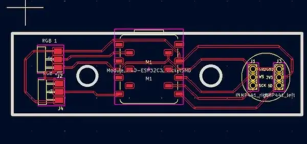
有关(输入)移动模块的更多详细信息参考:(input) Mobile Module - PCB design | Matthew's FabLab Journey (fabacademy.org)
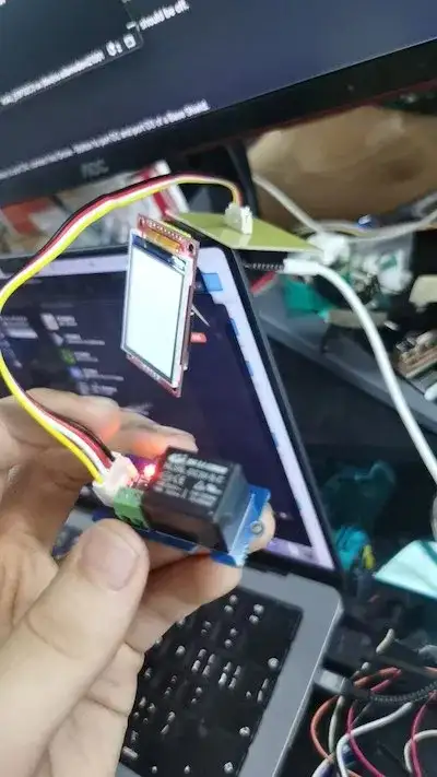
(输出)移动模块 - 接收和显示日历信息:
我希望这个模块接收日历信息,它可以控制一些东西,比如继电器。然后,我在PCB上添加了一个Grove端口和一个8 PinHeader P2.54mm:
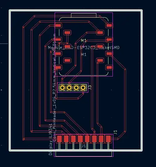
有关(输出)移动模块的更多详细信息:(Output) Mobile Module - PCB design | Matthew's FabLab Journey (fabacademy.org)
外观结构设计
输入模块设计:
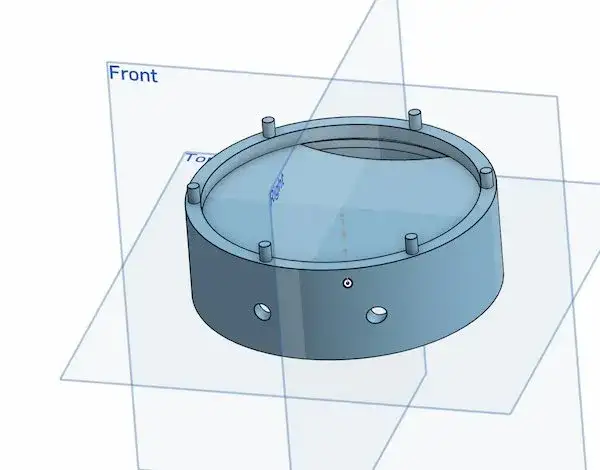
顶盖(3D打印):
中间部分(3D打印):
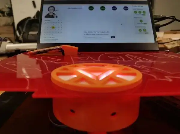
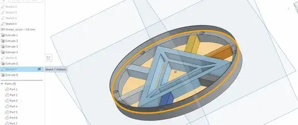
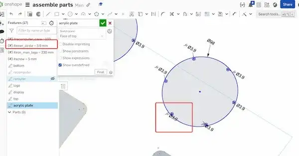
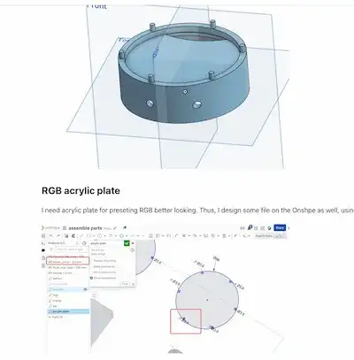
RGB灯罩部分(2D设计):
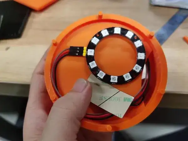
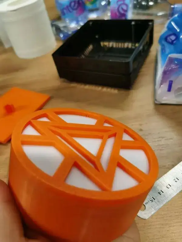
最终成品:
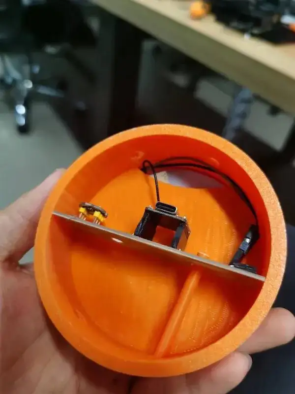
将RGB灯接线与XIAO天线一起延长至背部:
最后放置亚克力板盖上背部:

输出模块设计:
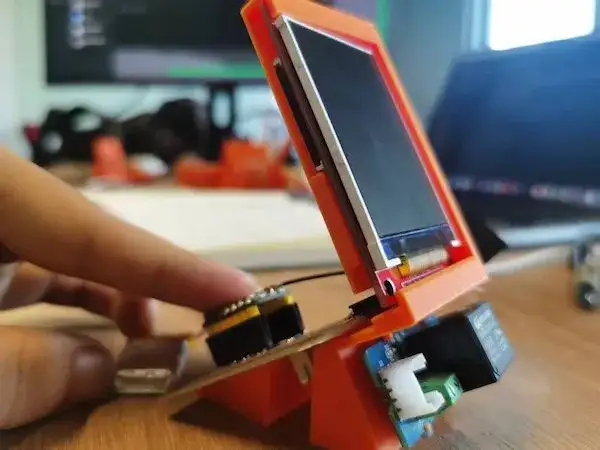
显示器支架和 Grove 继电器支架(3D 打印):
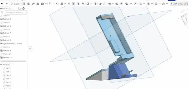
最终成品:
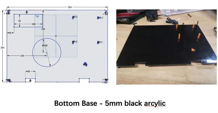
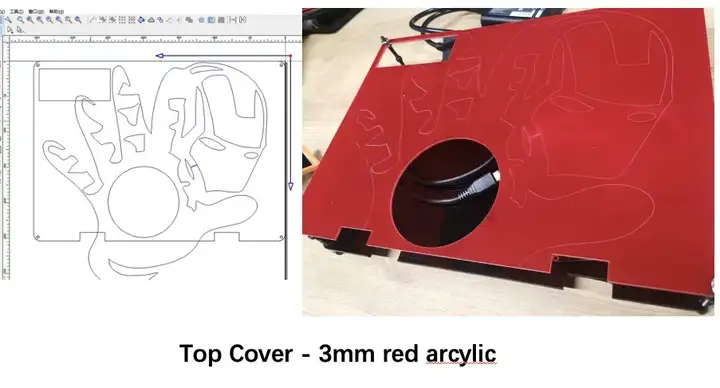
外壳设计-2D激光切割:
这部分工作是为了让作品看起来好看、整洁、合乎逻辑。
1、 RGB显示最好带有滤镜层。因此,在蓝图上切割一些亚克力板:
2、 由于我使用了一些大型设备/设备(reComputer 和 reRouter),我将使用两块大亚克力板将所有东西固定在一起:因此激光切割是必要的:
机箱设计-3D打印:
这部分是为了让作品看起来好看、整洁、合乎逻辑。
1、我的设备需要得到支持、修复,而不是到处移动。因此,我需要设计一些 3D 零件来固定它们:

出于其他考虑,我修改了初始方案:
整体搭建与封装
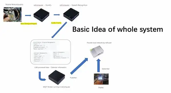
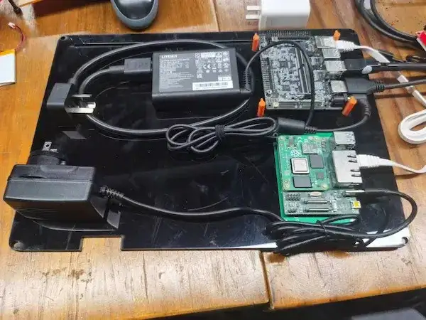
整体系统搭建基本思路:
-
主要计算设备:reComputer,提供MQTT代理,AI计算,运行LLM和浏览器网站。
-
网络设备(我想确保所有东西都是本地的):reRouter,提供Wi-Fi无线连接和电线连接。
-
一个带INMP441的语音输入移动模块
-
一个带有ILI9341的显示信息移动模块。
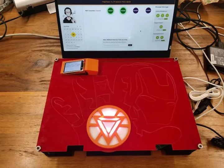
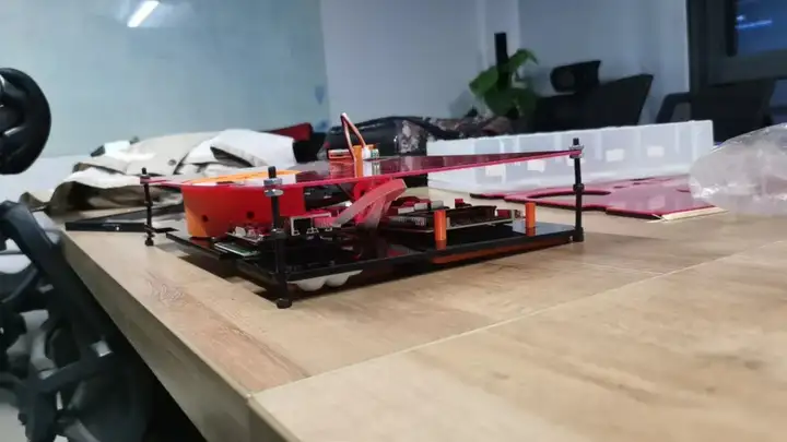
整体系统:
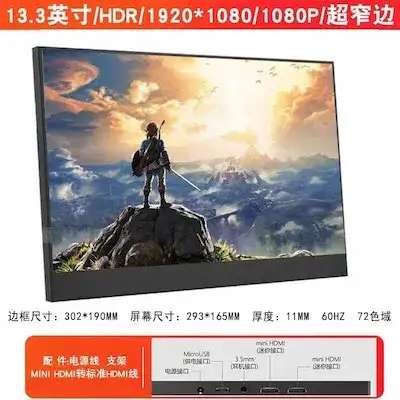
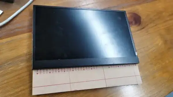
显示器与电源适配器:
对于显示器而言,为了整体项目可携带的目标,我不得不考虑一个可携带的监视器。我买了一个显示器,具体尺寸如图所示:
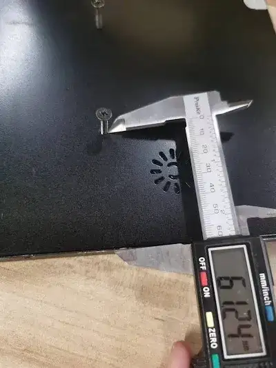
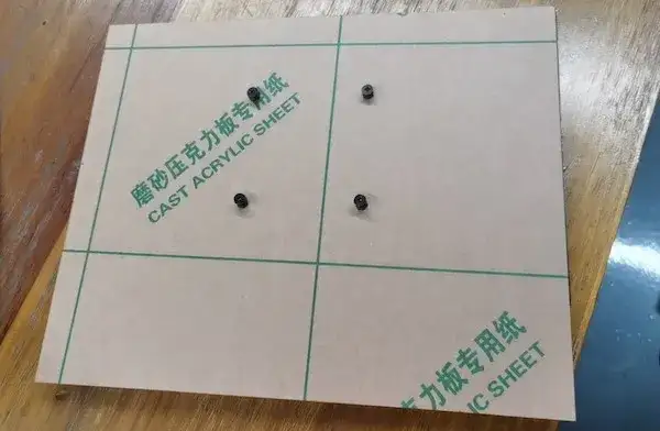
显示器后面有四个螺丝孔,然后我测量了螺丝孔到边缘的距离和孔之间的距离:

然后我需要计算显示板的长度,在这里一定要保证不会太长影响美观,也不会太短影响连接:
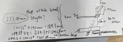
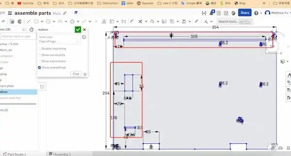
计算之后,我在OnShape上设计了显示器的附加板:
设计之后通过激光切割获得附加板:
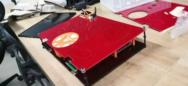
对于电源适配器,我也需要将安装绑在一起:
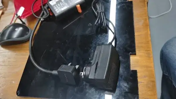
并且考虑到稳定显示器等问题,我需要在设计上保留每个板上的间隙:
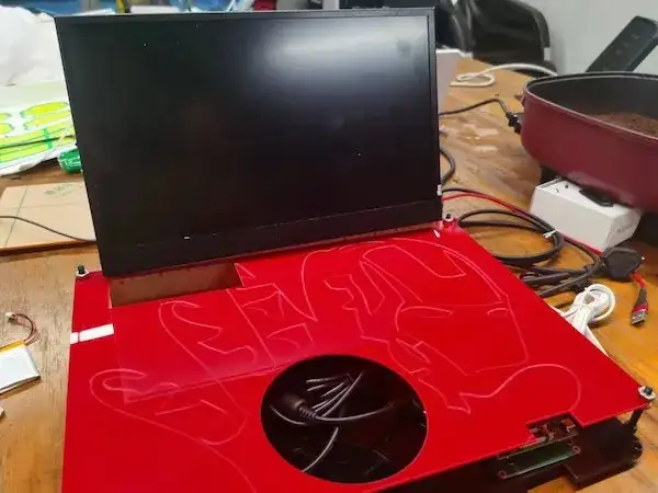
底部:

顶部:
切割电路板并将模块插入其中:
进行拧紧连接:
添加移动模块:
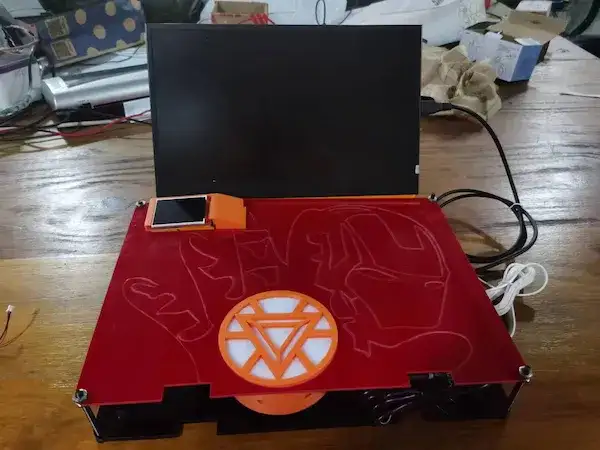
将移动模块移到外面:
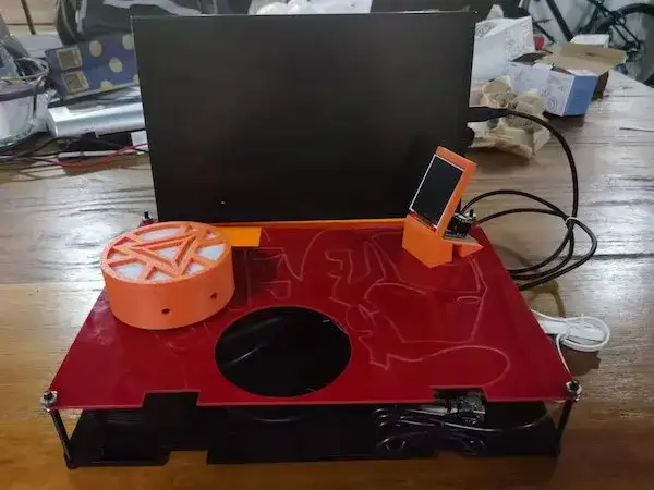
至此,一个基于XIAO ESP32C3的本地个人助理已经搭建完成!