1.配置eth-trunk进行绑定
LSW1interface Eth-Trunk 0
LSW1-Eth-Trunk0q
LSW1interface g0/0/2
LSW1-GigabitEthernet0/0/2eth-trunk 0
LSW1-GigabitEthernet0/0/2int g0/0/3
LSW1-GigabitEthernet0/0/3eth-trunk 0
LSW1-GigabitEthernet0/0/3display eth-trunk 0
2.创建vlan,划分接口类型
LSW1vlan 2
LSW1port-group group-member g0/0/4 to g0/0/5 Eth-Trunk 0
LSW1-port-groupport link-type trunk
LSW1-GigabitEthernet0/0/4port link-type trunk
LSW1-GigabitEthernet0/0/5port link-type trunk
LSW1-port-groupport trunk allow-pass vlan 2
LSW1-GigabitEthernet0/0/4port trunk allow-pass vlan 2
LSW1-GigabitEthernet0/0/5port trunk allow-pass vlan 2
LSW1-Eth-Trunk0port trunk allow-pass vlan 2

LSW2vlan 2
LSW2-vlan2q
LSW2port-group group-member g0/0/4 to g0/0/5 Eth-Trunk 0
LSW2-port-groupport trunk allow-pass vlan 2
LSW2-Eth-Trunk0port trunk allow-pass vlan 2

LSW3vlan 2
LSW3-vlan2q
LSW3-Ethernet0/0/3int e0/0/4
LSW3-Ethernet0/0/4port link-type access
LSW3-Ethernet0/0/4port default vlan 2
LSW3-Ethernet0/0/4q
LSW3port-group group-member e0/0/1 to e0/0/2
LSW3-port-groupport link-type trunk
LSW3-port-groupport trunk allow-pass vlan 2
LSW4vlan 2
LSW4-vlan2q
LSW4int e0/0/4
LSW4-Ethernet0/0/4port link-type access
LSW4-Ethernet0/0/4port default vlan 2
LSW4-Ethernet0/0/4q
LSW4port-group group-member e0/0/1 to e0/0/2
LSW4-port-groupport link-type trunk
LSW4-port-groupport trunk allow-pass vlan 2
3.配置生成树:
LSW1stp region-configuration
LSW1-mst-regionregion-name a
LSW1-mst-regioninstance 1 vlan 1
LSW1-mst-regioninstance 2 vlan 2
LSW1-mst-regionactive region-configuration
LSW1stp instance 1 root primary
LSW1stp instance 2 root secondary
LSW1stp instance 0 root primary

LSW2stp region-configuration
LSW2-mst-regioninstance 1 vlan 1
LSW2-mst-regioninstance 2 vlan 2
LSW2-mst-regionactive region-configuration
LSW2stp instance 1 root secondary
LSW2stp instance 2 root primary
LSW2stp instance 0 root secondary
LSW3stp region-configuration
LSW3-mst-regionregion-name a
LSW3-mst-regioninstance 1 vlan 1
LSW3-mst-regioninstance 2 vlan 2
LSW3-mst-regionactive region-configuration
LSW4stp region-configuration
LSW4-mst-regionregion-name a
LSW4-mst-regioninstance 1 vlan 1
LSW4-mst-regioninstance 2 vlan 2
LSW4-mst-regionactive region-configuration
LSW3port-group group-member e0/0/1 to e0/0/2
LSW3-port-groupstp edged-port enable
LSW3int e0/0/3
LSW3-Ethernet0/0/3stp instance 0 port priority 16
5.配置ip地址SVI:
LSW1int vlan 1
LSW1-Vlanif1ip add
LSW1-Vlanif1ip address 172.16.1.1 25
LSW1-Vlanif1int vlan 2
LSW1-Vlanif2ip address 172.16.1.129 25
LSW1-Vlanif2display ip interface brief

LSW2int vlan 1
LSW2-Vlanif1ip address 172.16.1.2 25
LSW2-Vlanif1int vlan 2
LSW2-Vlanif2ip address 172.16.1.130 25
LSW2-Vlanif2display ip interface brief

6.进行网关冗余VRRP:
LSW1int vlan 1
LSW1-Vlanif1vrrp vrid 1 virtual-ip 172.16.1.126
LSW1-Vlanif1vrrp vrid 1 priority 110
LSW1-Vlanif1vrrp vrid 1 track interface g0/0/1 reduced 20
LSW1int vlan 2
LSW1-Vlanif2vrrp vrid 1 virtual-ip 172.16.1.254

LSW2int vlan 1
LSW2-Vlanif1vrrp vrid 1 virtual-ip 172.16.1.126(vrid、virtual-ip需和LSW1保持一致)
LSW2int vlan 2
LSW2-Vlanif2vrrp vrid 1 virtual-ip 172.16.1.254
LSW2-Vlanif2vrrp vrid 1 priority 110
LSW2-Vlanif2vrrp vrid 1 track int g0/0/1 reduced 20
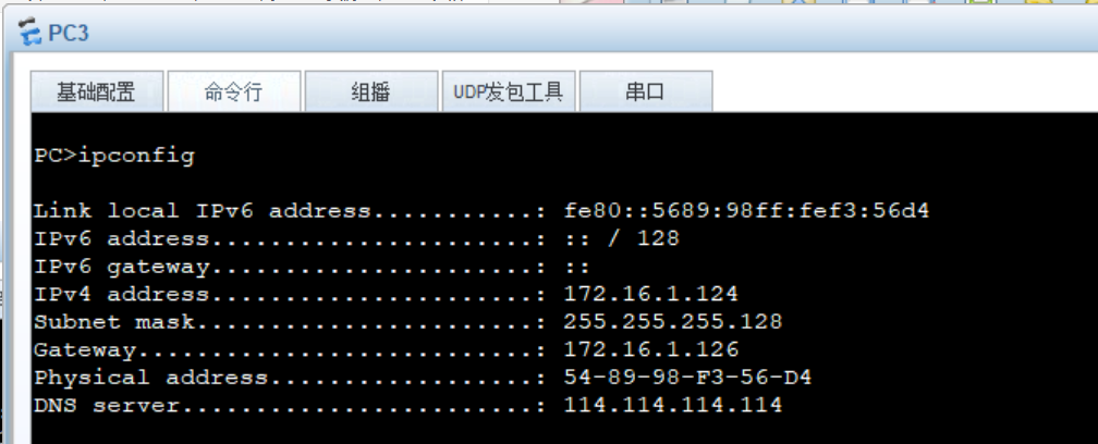
7.配置DHCP获取IP地址:
LSW1dhcp enable
LSW1ip pool a1
LSW1-ip-pool-a1net 172.16.1.0 mask 25
LSW1-ip-pool-a1gateway-list 172.16.1.126
LSW1-ip-pool-a1dns-list 114.114.114.114
LSW1-ip-pool-a1q
LSW1ip pool a2
LSW1-ip-pool-a2net 172.16.1.128 mask 25
LSW1-ip-pool-a2gateway-list 172.16.1.254
LSW1-ip-pool-a2dns-list 114.114.114.114
LSW1-ip-pool-a2q
LSW1int vlan 1
LSW1-Vlanif1dhcp select global
LSW1-Vlanif1int vlan 2
LSW1-Vlanif2dhcp select global
SW2dhcp enable
SW2ip pool a1
Info:It's successful to create an IP address pool.
SW2-ip-pool-a1net 172.16.1.0 mask 25
SW2-ip-pool-a1gateway-list 172.16.1.126
SW2-ip-pool-a1dns-list 114.114.114.114
SW2-ip-pool-a1q
SW2ip pool a2
Info:It's successful to create an IP address pool.
SW2-ip-pool-a2net 172.16.1.128 mask 25
SW2-ip-pool-a2gateway-list 172.16.1.254
SW2-ip-pool-a2dns-list 114.114.114.114
SW2-ip-pool-a2q
SW2int vlan 1
SW2-Vlanif1dhcp select global
SW2-Vlanif1int vlan 2
SW2-Vlanif2dhcp select global
8.对于上层路由器进行连接
SW1vlan 99
SW1-GigabitEthernet0/0/2int g0/0/1
SW1-GigabitEthernet0/0/1port link-type access
SW1-GigabitEthernet0/0/1port default vlan 99
SW1int vlan 99
SW1-Vlanif99ip add 172.16.0.2 30
SW2vlan 99
SW2-vlan99int g0/0/1
SW2-GigabitEthernet0/0/1port link-type access
SW2-GigabitEthernet0/0/1q
SW2int vlan 99
SW2-Vlanif99ip add 172.16.0.6 30
9.配置沉默接口:
LSW1ospf 1
SW1-ospf-1silent-interface all
SW1-ospf-1undo silent-interface GigabitEthernet 0/0/1
SW1-ospf-1undo silent-interface Vlanif 99
SW1-ospf-1undo silent-interface Eth-Trunk 0
SW1-ospf-1undo silent-interface Vlanif 1
SW2ospf 1
SW2-ospf-1silent-interface all
SW2-ospf-1undo silent-interface GigabitEthernet 0/0/1
SW2-ospf-1undo silent-interface Vlanif 99
SW2-ospf-1undo silent-interface Eth-Trunk 0
SW2-ospf-1undo silent-interface Vlanif 1
三、配置路由器部分:
1.配置ospf协议
R2ospf 1 router-id 2.2.2.2
R2-ospf-1area 0
R2-ospf-1-area-0.0.0.0net 172.16.0.0 0.0.0.255
SW1ospf 1 router-id 3.3.3.3
SW1-ospf-1area 0
SW1-ospf-1-area-0.0.0.0net 172.16.0.2 0.0.0.0
SW1-ospf-1area 1
SW1-ospf-1-area-0.0.0.1net 172.16.1.0 0.0.0.255
SW1-ospf-1-area-0.0.0.1
SW2ospf 1 router-id 4.4.4.4
SW2-ospf-1area 0
SW2-ospf-1-area-0.0.0.0net 172.16.0.6 0.0.0.0
SW2-ospf-1-area-0.0.0.0q
SW2-ospf-1area 1
SW2-ospf-1-area-0.0.0.1net 172.16.1.0 0.0.0.255
2.配置缺省路由
R2ip route-static 0.0.0.0 0 12.1.1.1
R2ospf 1 router-id 2.2.2.2
R2-ospf-1default-route-advertise
3.进行路由汇总:
SW1ospf 1
SW1-ospf-1area 1
SW1-ospf-1-area-0.0.0.1abr-summary 172.16.1.0 255.255.255.0
SW2ospf 1
SW2-ospf-1area 1
SW2-ospf-1-area-0.0.0.1abr-summary 172.16.1.0 255.255.255.0
4.防止路由黑洞
SW1ip route-static 172.16.1.0 24 NULL 0
SW2ip route-static 172.16.1.0 24 NULL 0
5.配置nat,进行上网:
R2acl 2000
R2-acl-basic-2000rule permit source 172.16.0.0 0.0.255.255
R2-acl-basic-2000q
R2int g0/0/0
R2-GigabitEthernet0/0/0nat outbound 2000


确定 ISP 连接接口及 IP 配置
- 明确 R1 与 ISP 相连的接口(假设为
GE 0/0/0) ,在 R1上仅进行 IP 地址相关配置。若已知 ISP 侧 IP 地址为12.1.1.1,则在 R1 设备上配置:
plaintext
[R1]interface GE0/0/0
[R1-GigabitEthernet0/0/0]ip address 12.1.1.2 30
此配置仅为接口设置 IP 地址,符合 "只能配置 IP 地址" 的要求 。
确保连接及路由可达
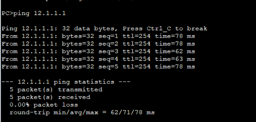
- 链路连通性测试 :在 R1 上使用
ping命令测试与 ISP 的连通性,如ping 12.1.1.1,确保物理链路和 IP 层连通正常。 - 路由配置 :在 R1 及相关网络设备(如 LSW1、LSW2 等 )上,通过 OSPF 等动态路由协议(已配置情况下 )或静态路由,保证内网到 ISP 方向路由可达。例如在 R1 上,已配置缺省路由
[R1]ip route-static 0.0.0.0 0 12.1.1.1,将所有未知流量导向 ISP ;在 LSW1 和 LSW2 上,通过 OSPF 学习到前往 R2 及 ISP 方向的路由。
安全策略限制
为进一步确保 ISP 只能配置 IP 地址,可在 R2 上配置访问控制列表(ACL ) ,限制对 ISP 设备的其他访问操作(假设 ISP 设备不允许除 IP 配置外的其他远程管理等操作 )。例如:
plaintext
[R1]acl 3000
[R1-acl-adv-3000]rule deny ip source any destination 12.1.1.1 0.0.0.0 (禁止内网主动访问 ISP 除 IP 相关配置外的其他服务 )
[R1-acl-adv-3000]rule permit ip source 12.1.1.2 0.0.0.0 destination any (允许 R2 与 ISP 正常通信 )
[R1-acl-adv-3000]quit
[R1]interface GE0/0/0
[R1-GigabitEthernet0/0/0]traffic-filter inbound acl 3000 (在入方向应用 ACL 策略 )
通过以上操作,在网络连接和安全控制层面实现 ISP 仅进行 IP 地址配置的要求 。
ping 12.1.1.1