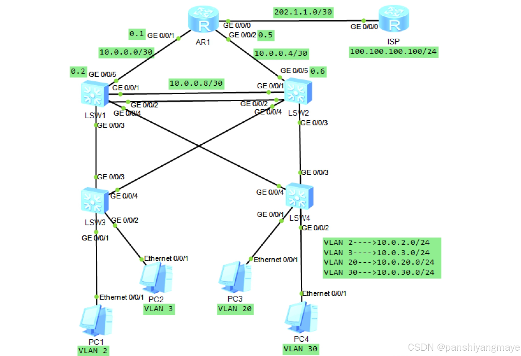
一、拓扑图
二、需求
1.按照图示的VLAN及IP地址需求,完成相关配置
2.要求SW1为VLAN 2/3的主根及主网关,SW2为vlan 20/30的主根及主网关,SW1和SW2互为备份
3.上层通过静态路由协议完成数据通信过程
4.AR1为企业出口路由器
5.要求全网可达
三、需求分析
1、VLAN及IP地址的配置:
- VLAN 2的IP地址段:10.0.2.0/24
- VLAN 3的IP地址段:10.0.3.0/24
- VLAN 20的IP地址段:10.0.20.0/24
- VLAN 30的IP地址段:10.0.30.0/24
2、路由器配置:
- AR1路由器IP地址:202.1.1.0/30
- ISP连接部分IP地址:100.100.100.100/24
3、主根及主网关配置:
- SW1交换机需设置为VLAN 2和VLAN 3的主根交换机,并作为这些VLAN的主网关。
- SW2交换机需设置为VLAN 20和VLAN 30的主根交换机,并作为这些VLAN的主网关。
- SW1和SW2交换机需配置为互为备份。
4、静态路由协议:
通过静态路由协议完成数据通信过程,确保网络路径的明确和稳定。
5、企业出口路由器:
AR1路由器作为企业出口路由器,负责与外部网络的连接和数据交换。
6、全网可达性需求:
网络配置需确保所有设备之间的通信畅通无阻,实现全网可达。
四、所有配置的文字描述及代码
1、配置VLAN,放通链路
(1)接入层设备
-
SW3配置:
[sw3]vlan batch 2 3 20 30
[sw3]interface g 0/0/1
[sw3-GigabitEthernet0/0/1]port link-type access
[sw3-GigabitEthernet0/0/1]port default vlan 2[sw3-GigabitEthernet0/0/1]int g 0/0/2
[sw3-GigabitEthernet0/0/2]port link-type access
[sw3-GigabitEthernet0/0/2]port default vlan 3[sw3-GigabitEthernet0/0/2]int g 0/0/3
[sw3-GigabitEthernet0/0/3]port link-type trunk
[sw3-GigabitEthernet0/0/3]port trunk allow-pass vlan 2 3 20 30[sw3-GigabitEthernet0/0/3]int g 0/0/4
[sw3-GigabitEthernet0/0/4]port link-type trunk
[sw3-GigabitEthernet0/0/4]port trunk allow-pass vlan 2 3 20 30 -
SW4的配置:
[sw4]vlan batch 2 3 20 30
[sw4]int g 0/0/1
[sw4-GigabitEthernet0/0/1]port link-type access
[sw4-GigabitEthernet0/0/1]port default vlan 20[sw4-GigabitEthernet0/0/1]int g 0/0/2
[sw4-GigabitEthernet0/0/2]po li a
[sw4-GigabitEthernet0/0/2]po de v 30[sw4-GigabitEthernet0/0/2]int g 0/0/3
[sw4-GigabitEthernet0/0/3]port link-type trunk
[sw4-GigabitEthernet0/0/3]port trunk allow-pass vlan 2 3 20 30[sw4-GigabitEthernet0/0/3]int g 0/0/4
[sw4-GigabitEthernet0/0/4]po li t
[sw4-GigabitEthernet0/0/4]po t all v 2 3 20 30
(2)汇聚层设备
-
SW1的配置:
[sw1]vlan batch 2 3 20 30
[sw1]interface Eth-Trunk 0
[sw1-Eth-Trunk0]trunkport GigabitEthernet 0/0/1 to 0/0/2
[sw1-Eth-Trunk0]port link-type trunk
[sw1-Eth-Trunk0]port trunk allow-pass vlan 2 3 20 30
[sw1-Eth-Trunk0]q[sw1]int g 0/0/3
[sw1-GigabitEthernet0/0/3]po li t
[sw1-GigabitEthernet0/0/3]po t all v 2 3 20 30[sw1-GigabitEthernet0/0/3]int g0/0/4
[sw1-GigabitEthernet0/0/4]po li t
[sw1-GigabitEthernet0/0/4]po t all v 2 3 20 30 -
SW2的配置:
[sw2]vlan batch 2 3 20 30
[sw2]interface Eth-Trunk 0
[sw2-Eth-Trunk0]trunkport GigabitEthernet 0/0/1 to 0/0/2[sw2-Eth-Trunk0]po li t
[sw2-Eth-Trunk0]po t all v 2 3 20 30[sw2-Eth-Trunk0]int g 0/0/3
[sw2-GigabitEthernet0/0/3]po li t
[sw2-GigabitEthernet0/0/3]po t all v 2 3 20 30[sw2-GigabitEthernet0/0/3]int g 0/0/4
[sw2-GigabitEthernet0/0/4]po li t
[sw2-GigabitEthernet0/0/4]po t all v 2 3 20 30
2、生成树协议
(1)让四台交换机认知到mstp内容,两条链路互为备份。
-
将VLAN 2和VLAN 3归为实例1,构造一棵生成树,使SW1为主根,SW2为备份根;
-
将VLAN 20和VLAN 30归为实例2,构造一棵生成树,使SW2为主根,SW1为备份根。
[sw1]stp en
[sw1]stp mode mstp
[sw1]stp region-configuration
[sw1-mst-region] region-name aa
[sw1-mst-region] revision-level 100
[sw1-mst-region] instance 1 vlan 2 to 3
[sw1-mst-region] instance 2 vlan 20 30
[sw1-mst-region] active region-configuration[sw2]stp en
[sw2]stp mode mstp
[sw2]stp region-configuration
[sw2-mst-region] region-name aa
[sw2-mst-region] revision-level 100
[sw2-mst-region] instance 1 vlan 2 to 3
[sw2-mst-region] instance 2 vlan 20 30
[sw2-mst-region] active region-configuration[sw3]stp en
[sw3]stp mode mstp
[sw3]stp region-configuration
[sw3-mst-region] region-name aa
[sw3-mst-region] revision-level 100
[sw3-mst-region] instance 1 vlan 2 to 3
[sw3-mst-region] instance 2 vlan 20 30
[sw3-mst-region] active region-configuration[sw4]stp en
[sw4]stp mode mstp
[sw4]stp region-configuration
[sw4-mst-region] region-name aa
[sw4-mst-region] revision-level 100
[sw4-mst-region] instance 1 vlan 2 to 3
[sw4-mst-region] instance 2 vlan 20 30
[sw4-mst-region] active region-configuration
(2)让SW1成为实例1的主根,SW2成为实例2的主根。
[sw1]stp instance 1 root primary
[sw1]stp instance 2 root secondary

[sw2]stp instance 1 root secondary
[sw2]stp instance 2 root primary
(3)在SW1的0/0/3接口开启根保护功能(防止新增的交换机抢占根角色)。
[sw1]int g 0/0/3
[sw1-GigabitEthernet0/0/3]stp root-protection
(4)加快收敛机制,在SW3和SW4的0/0/1和0/0/2开启边端口功能(让接口无需参与stp工作,直接进入转发状态)。
[sw3]int g 0/0/1
[sw3-GigabitEthernet0/0/1]stp edged-port enable

[sw3-GigabitEthernet0/0/1]int g 0/0/2
[sw3-GigabitEthernet0/0/2]stp edged-port enable

[sw4]int g 0/0/1
[sw4-GigabitEthernet0/0/1]stp edged-port enable

[sw4-GigabitEthernet0/0/1]int g 0/0/2
[sw4-GigabitEthernet0/0/2]stp edged-port enable
3、在SW1和SW2中配置VRRP
(1)三层接口用Vlanif,SW1成为VLAN 2和VLAN 3的主网关
[sw1]int Vlanif 2
[sw1-Vlanif2]ip add 10.0.2.1 24
[sw1-Vlanif2]vrrp vrid  1 virtual-ip 10.0.2.254 (虚拟接口)
[sw1-Vlanif2]vrrp vrid 1 priority 120 (优先级)
[sw1-Vlanif2]vrrp vrid 1 preempt-mode timer delay 20 (抢占延迟)
[sw1-Vlanif2]vrrp vrid 1 track interface GigabitEthernet 0/0/5 reduced 30
[sw1-Vlanif2]q

[sw1]int Vlanif 3
[sw1-Vlanif3]ip add 10.0.3.1 24
[sw1-Vlanif3]vrrp vrid 1 virtual-ip 10.0.3.254
[sw1-Vlanif3]vrrp vrid 1 priority 120
[sw1-Vlanif3]vrrp vrid 1 preempt-mode timer delay 20
[sw1-Vlanif3]vrrp vrid 1 track interface GigabitEthernet 0/0/5 reduced 30
(2)SW1成为VLAN 20和VLAN 30的备份网关,无需调整优先级、抢占延迟和上行链路监控。
[sw1]int Vlanif 20
[sw1-Vlanif20]ip add 10.0.20.1 24
[sw1-Vlanif20]vrrp vrid 1 virtual-ip 10.0.20.254
[sw1-Vlanif20]q

[sw1]int Vlanif 30
[sw1-Vlanif30]ip add 10.0.30.1 24
[sw1-Vlanif30]vrrp vrid 1 virtual-ip 10.0.30.254
(3)SW2中的VRRP配置与SW1相反,SW2是VLAN 2和VLAN 3的备份网关,是VLAN 20和VLAN 30的主网关。
[sw2]int Vlanif 2
[sw2-Vlanif2]ip ad 10.0.2.2 24
[sw2-Vlanif2]vrrp vrid 1 virtual-ip 10.0.2.254
[sw2-Vlanif2]q
[sw2]int Vlanif 3
[sw2-Vlanif3]ip ad 10.0.3.2 24
[sw2-Vlanif3]vrrp vrid 1 virtual-ip 10.0.3.254
[sw2-Vlanif3]q
[sw2]int Vlanif 20
[sw2-Vlanif20]ip ad 10.0.20.2 24
[sw2-Vlanif20]vrrp vrid 1 virtual-ip 10.0.20.254
[sw2-Vlanif20]vrrp vrid 1 priority 120
[sw2-Vlanif20]vrrp vrid 1 preempt-mode timer delay 20
[sw2-Vlanif20]vrrp vrid 1 track in GigabitEthernet 0/0/5 reduced 30
[sw2-Vlanif20]q
[sw2]int Vlanif 30
[sw2-Vlanif30]ip ad 10.0.30.2 24
[sw2-Vlanif30]vrrp vrid 1 virtual-ip 10.0.30.254
[sw2-Vlanif30]vrrp vrid 1 priority 120
[sw2-Vlanif30]vrrp vrid 1 preempt-mode timer delay 20
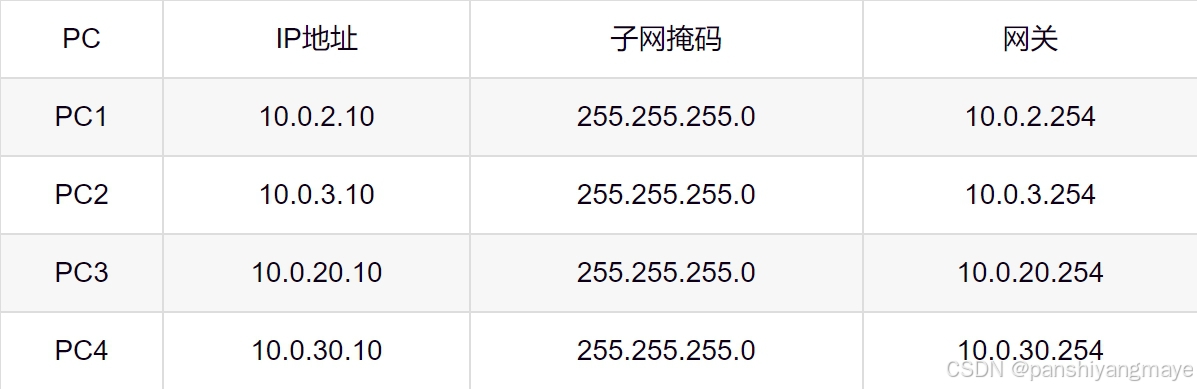
[sw2-Vlanif30]vrrp vrid 1 track in GigabitEthernet 0/0/5 reduced 304、用静态IP配置PC的IP地址
5、三层配置
SW1和SW2与AR1互联,配置VLAN和接口IP地址(互联接口在交换机上称为互联VLAN)。
-
SW1的配置:
[sw1]vlan 11
[sw1-vlan11]int g 0/0/5
[sw1-GigabitEthernet0/0/5]port link-type access
[sw1-GigabitEthernet0/0/5]port default vlan 11
[sw1-GigabitEthernet0/0/5]q[sw1]int Vlanif 11
[sw1-Vlanif11]ip ad 10.0.0.2 30 -
SW2的配置:
[sw2]vlan 12
[sw2-vlan12]int g 0/0/5
[sw2-GigabitEthernet0/0/5]port link-type access
[sw2-GigabitEthernet0/0/5]port default vlan 12
[sw2-GigabitEthernet0/0/5]q[sw2]int Vlanif 12
[sw2-Vlanif12]ip ad 10.0.0.6 30 -
AR1的配置:
[AR1]int g 0/0/1
[AR1-GigabitEthernet0/0/1]ip ad 10.0.0.1 30[AR1-GigabitEthernet0/0/1]int g 0/0/2
[AR1-GigabitEthernet0/0/2]ip ad 10.0.0.5 30
6、OSPF动态路由协议
(1)SW1和SW2分别宣告对应的五个接口,AR1宣告两个接口。
[sw1]ospf 1
[sw1-ospf-1]area  0
[sw1-ospf-1-area-0.0.0.0]network 10.0.2.1 0.0.0.0
[sw1-ospf-1-area-0.0.0.0]network 10.0.3.1 0.0.0.0
[sw1-ospf-1-area-0.0.0.0]network 10.0.0.2 0.0.0.0
[sw1-ospf-1-area-0.0.0.0]network 10.0.20.1 0.0.0.0
[sw1-ospf-1-area-0.0.0.0]network 10.0.30.1 0.0.0.0

[sw2]ospf 1
[sw2-ospf-1]area  0
[sw2-ospf-1-area-0.0.0.0]network 10.0.2.2 0.0.0.0
[sw2-ospf-1-area-0.0.0.0]network 10.0.3.2 0.0.0.0
[sw2-ospf-1-area-0.0.0.0]network 10.0.0.6 0.0.0.0
[sw2-ospf-1-area-0.0.0.0]network 10.0.20.2 0.0.0.0
[sw2-ospf-1-area-0.0.0.0]network 10.0.30.2 0.0.0.0

[AR1]ospf 1
[AR1-ospf-1]area 0
[AR1-ospf-1-area-0.0.0.0]network 10.0.0.1 0.0.0.0
[AR1-ospf-1-area-0.0.0.0]network 10.0.0.5 0.0.0.0
(2)让四个Vlanif接口成为静默接口(接口不允许发送和接收OSPF报文)。
[sw1-ospf-1]silent-interface Vlanif 2
[sw1-ospf-1]silent-interface Vlanif 3
[sw1-ospf-1]silent-interface Vlanif 20
[sw1-ospf-1]silent-interface Vlanif 30

[sw2-ospf-1]silent-interface Vlanif 2
[sw2-ospf-1]silent-interface Vlanif 3
[sw2-ospf-1]silent-interface Vlanif 20
[sw2-ospf-1]silent-interface Vlanif 30
(3)在SW1和SW2之间的链路配置VLAN,并放通链路、宣告。
[sw1]vlan 13
[sw1-vlan13]q

[sw1]int e 0
[sw1-Eth-Trunk0]port trunk allow-pass vlan 13
[sw1]int Vlanif 13
[sw1-Vlanif13]ip add 10.0.0.9 30
[sw1-Vlanif13]q

[sw1]ospf 1
[sw1-ospf-1]area 0
[sw1-ospf-1-area-0.0.0.0]network 10.0.0.9 0.0.0.0

[sw2]vlan 13
[sw2-vlan13]q

[sw2]int e 0
[sw2-Eth-Trunk0]port trunk allow-pass vlan 13
[sw2]int Vlanif 13
[sw2-Vlanif13]ip add 10.0.0.10 30
[sw2-Vlanif13]q

[sw2]ospf 1
[sw2-ospf-1]area 0
[sw2-ospf-1-area-0.0.0.0]network 10.0.0.10 0.0.0.0
7、PC连通外网
(1)给AR1和ISP之间的链路接口和ISP的环回接口配置IP地址。
[AR1]int g 0/0/0
[AR1-GigabitEthernet0/0/0]ip ad 202.1.1.1 30
[AR1]ip route-static 0.0.0.0 0 202.1.1.2
[AR1-ospf-1]default-route-advertise

[ISP]int g 0/0/0
[ISP-GigabitEthernet0/0/0]ip ad 202.1.1.2 30
[ISP-LoopBack0]q

[ISP]int l0
[ISP-LoopBack0]ip ad 100.100.100.100 24
(2)给AR1写一条缺省路由指向运营商,保证成功访问外网,并配置NAT,使企业内网(私网)和运营商(公网)连通。
[AR1]ip route-static 0.0.0.0 0 202.1.1.2
[AR1]ospf 1
[AR1-ospf-1]default-route-advertise
[AR1-ospf-1]q

[AR1]acl 2000
[AR1-acl-basic-2000]rule permit source 10.0.0.0 0.0.255.255
[AR1-GigabitEthernet0/0/0]nat outbound 2000
五、结果
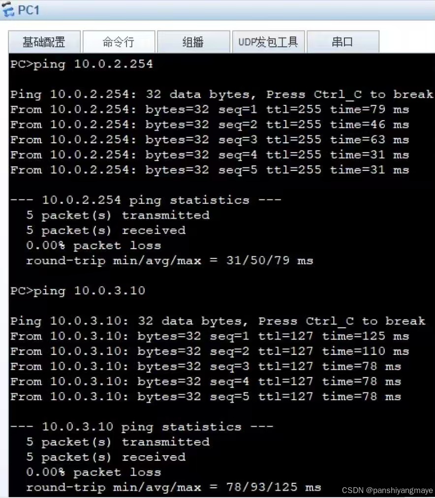
(1)用PC1分别ping PC2、PC3、PC4,检测连通性,此时四个VLAN互通。
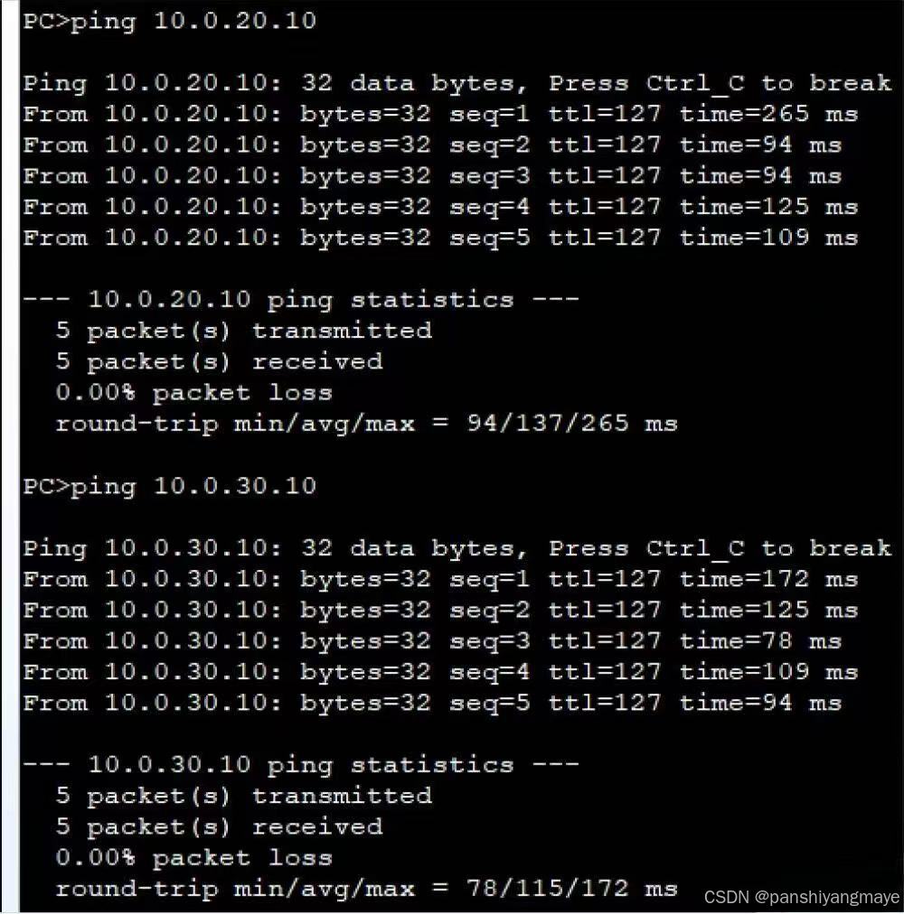
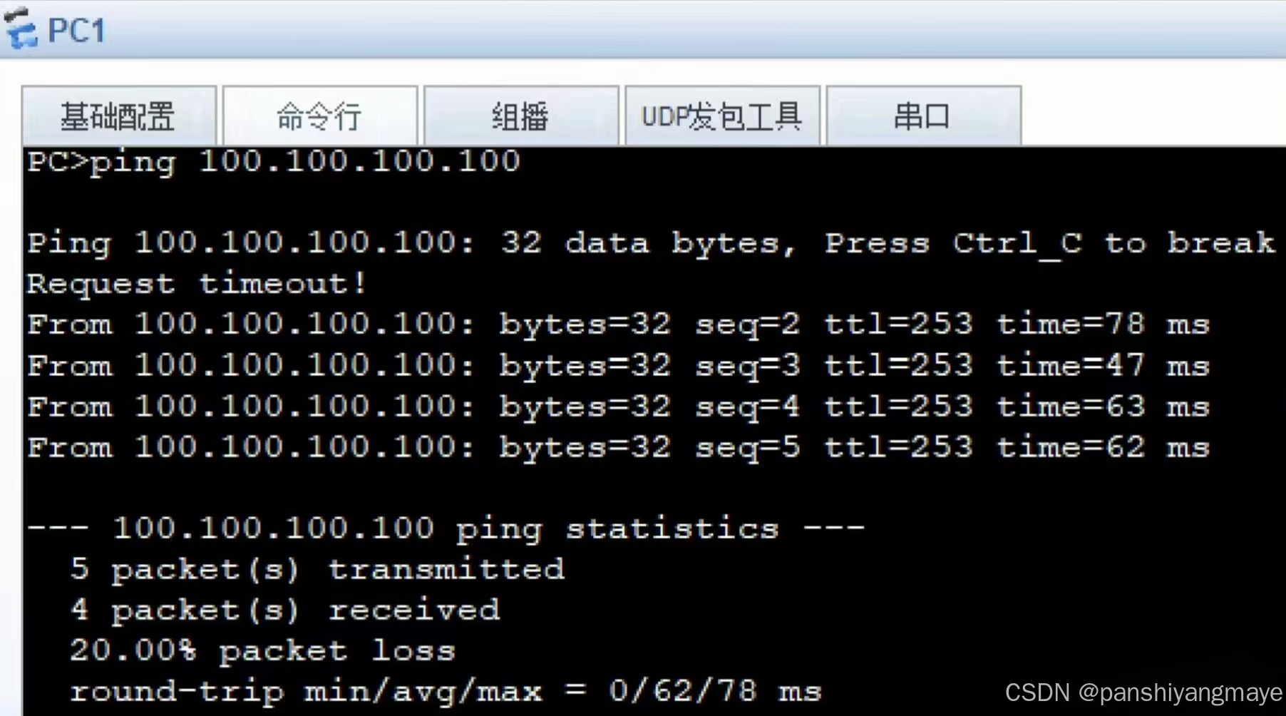
(2)在PC1 ping ISP的环回接口,检测连通性,实现全网可达。