几何体是什么
几何体就像3D模型的"骨架" ,它定义了物体的形状(比如一个立方体有几个角、球体有多圆),但不包含颜色、纹理等表面细节
其本质是一组数学数据,包含:
- 顶点(Vertices) : 3D空间中的点(想象立方体的8个角)
- 面(Faces) : 由3个顶点组成的三角形(所有复杂形状都由小三角面拼成)
- 法线(Normals) : 每个面的朝向(决定光线如何照射)
- UV坐标: 将2D贴图"包裹"到3D表面的定位点(类似地球仪的经纬线)
使用点模型可视化立方体几何体案例
效果如图

前面的章节已经学习过点模型Points,这里就不再赘述了,要实现如图效果需要先要了解下BoxGeometry的各个参数

前三个参数我们已经很熟悉了,这里要关注后面三个参数,它们都是用来控制分段的,代表的就是 X/Y/Z轴上的段数,先来实现第一个立方体我们便知是怎么回事
js
const material = new THREE.PointsMaterial({ // 创建点材质
    size: 0.05, // 点的大小
    color: 'deepskyblue' // 点的颜色
});

const points1 = new THREE.Points( // 创建点
    new THREE.BoxGeometry(1, 1, 1, 1, 1, 1), // 创建立方体几何
    material // 使用点材质
);
points1.position.set(-2,0,0)
scene.add(points1)
这里设置 XYZ轴上的分段都为1,我们修改X轴分段为5

从图中可以看到X轴上被分为5段,同理修改YZ轴上的分段我们就能得到本案例呈现的效果
材质索引案例
效果如图

需要了解的API
MeshDepthMaterial
MeshDepthMaterial 是将物体到相机的距离转化为灰度颜色的特殊材质
简单来说就是用灰度变化表示物体的远近关系,想象你用手机自拍时
- 离镜头最近的鼻子 → 在深度材质中显示为 白色
- 稍远的耳朵 → 显示为 浅灰色
- 远处的背景 → 显示为 深灰甚至黑色
让我们开始编码实现该案例, 创建材质数组,然后根据几何体的材质索引应用材质到几何体的每个面上
js
const materials = [
    new THREE.MeshNormalMaterial(),
    new THREE.MeshDepthMaterial(), // 深度材质
]

const geo = new THREE.BoxGeometry(1, 1, 1)
geo.groups.forEach((face,i)=> {
    face.materialIndex = face.materialIndex % materials.length; // 分配材质索引
})
const cube = new THREE.Mesh(geo, materials);
scene.add(cube);
canvas绘制几何体贴图案例
先看效果

这其实是一个非常简单的案例,使用canvas进行绘制,CanvasTexture创建纹理,之前的章节有谈及使用方式
js
const createCanvasTexture = (draw, size = 64) => {
    const canvas = document.createElement('canvas'),
    ctx = canvas.getContext('2d');
    canvas.width = size;
    canvas.height = size;
    draw(ctx, canvas)
    const texture = new THREE.CanvasTexture(canvas);
    texture.magFilter = THREE.NearestFilter;
    texture.minFilter = THREE.NearestFilter;
    return texture;
}

const textur_map = createCanvasTexture((ctx, canvas) => {
    ctx.fillStyle = 'deepskyblue';
    ctx.fillRect(0, 0, canvas.width, canvas.height);
    ctx.strokeStyle = 'deeppink';
    ctx.beginPath();
    ctx.lineWidth = 5;
    ctx.rect(1,1,canvas.width -2 ,canvas.height -2);
    ctx.stroke();
})

const cube = new THREE.Mesh(
    new THREE.BoxGeometry(1, 1, 1),
    new THREE.MeshBasicMaterial({map: textur_map})
);
关于灯光对canvas贴图影响的案例
先看效果

这里沿用上个案例的效果,更换Mesh材质为高光材质MeshPhongMaterial
js
const cube = new THREE.Mesh(
    new THREE.BoxGeometry( 1, 1, 1 ),
    new THREE.MeshPhongMaterial({
        map: texture_map,
        emissive: new THREE.Color(1, 1, 1),
        emissiveMap: texture_emissive,
        emissiveIntensity: 0.2,
    })
)
需要了解的API
MeshPhongMaterial
这是一种模拟光滑物体反光效果的材质(又称冯氏材质),比如塑料、陶瓷或金属漆面。它能呈现逼真的高光反射,让 3D 物体在光照下产生"亮闪闪"的光斑效果。
想象你用手电筒照射一个玻璃球:
- 漫反射光(基础颜色)→ 球体本身的颜色
- 镜面反射光(高光点)→ 手电筒在球面上形成的白色光斑
- 环境光 (暗部细节)→ 球体背光处的微弱补光
冯氏材质通过数学公式精确模拟这三种光线交互,形成逼真光泽感。
看下官方对emissiive和emissiveMap的说明

创建放射贴图,设置放射光颜色为白色
js
const texture_emissive = createCanvasTexture( (ctx, canvas) => {
    let i = 0;
    const w = 8, h = 5, len = w * h;
    const pw = canvas.width / w;
    const ph = canvas.height / h;
    while(i < len){
        const x = i % w;
        const y = Math.floor(i / w);
        const px = x * pw;
        const py = y * ph;
        const v = Math.random();
        const color = new THREE.Color(v, v, v);
        ctx.fillStyle =  color.getStyle();
        ctx.fillRect(px, py, pw, ph);
        i += 1;
    }
});
尝试修改放射光颜色为黑色,你将无法看见放射贴图效果
边缘几何体构建案例
效果如图

关于EdgesGeomrtry请查看Three.js-硬要自学系列33之专项学习基础材质在这篇文章中有介绍,代码如下
js
const geometry = new THREE.ConeGeometry( 1, 2, 32 ), // 半径,高度,分段数
edgeGeo = new THREE.EdgesGeometry( geometry, 1 ); // 边缘几何体,分段数
const line = new THREE.LineSegments( edgeGeo, new THREE.LineBasicMaterial( { color: 'deepskyblue' } ) );

scene.add( line );
UV贴图案例
效果如图

首先我们使用canvas来创建纹理,然后贴图
js
const canvas = document.createElement('canvas');
const ctx = canvas.getContext('2d');
canvas.width = canvas.height = 512;
ctx.fillStyle = 'white';
ctx.fillRect( 0, 0, canvas.width, canvas.height);
const w = 4;
const s = canvas.width / 4;
['red','lime','blue','yellow','cyan','purple'].forEach( (style, i) => {
    const gx = i % w;
    const gy = Math.floor( i / w );
    const x = gx * s;
    const y = gy * s;
    ctx.fillStyle = style;
    ctx.fillRect(x, y, s, s);
});
const texture = new THREE.CanvasTexture(canvas);
texture.magFilter = THREE.NearestFilter;
console.log(texture)

const material = new THREE.MeshBasicMaterial({map: texture,transparent: true,opacity: 0.5,side: THREE.DoubleSide});
const cube = new THREE.Mesh( geometry, material );
scene.add( cube)
我们能看到每个面都呈现出相同的纹理贴图,我们来修改下第一个面的UV坐标
js
// 获取几何体的uv属性
const att_uv = geometry.getAttribute('uv');
// 设置第一个顶点的uv坐标
att_uv.setXY(0, 0.25, 1.00);
// 设置第二个顶点的uv坐标
att_uv.setXY(1, 0.25, 0.75);
// 设置第三个顶点的uv坐标
att_uv.setXY(2, 0.50, 1.00);
// 设置第四个顶点的uv坐标
att_uv.setXY(3, 0.50, 0.75);
于是我们就看到如下界面,第一个面呈现绿色,是因为我们将uv坐标移动到了第二个绿色方块位置

调整下uv坐标到第三个方块上,就能很好理解了
js
// 设置第一个顶点的uv坐标
att_uv.setXY(0, 0.5, 1.00);
// 设置第二个顶点的uv坐标
att_uv.setXY(1, 0.5, 0.75);
// 设置第三个顶点的uv坐标
att_uv.setXY(2, 0.75, 1.00);
// 设置第四个顶点的uv坐标
att_uv.setXY(3, 0.75, 0.75);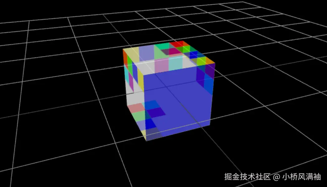
设置uv变换案例
先看效果

该案例中如何设置每个面的方式在上一章节中有介绍这里就不再赘述,这里主要来讲下数字变化这块的实现,以下是核心代码如下
js
const ORDERS = [
    [0,1,2,3],
    [0,2,1,3],
    [2,3,0,1],
    [3,1,2,0]
];

const update = (frame, frameMax) => {
    const a1 = frame / frameMax;
    mesh1.rotation.y = Math.PI * 2 * a1;
    mesh1.rotation.x = Math.PI * 8 * a1;
    if(frame % 30 === 0){
        let index_face = 0;
        while(index_face < 6){
            const index_cell = Math.floor( Math.random() * 6 );
            const order = ORDERS[ Math.floor( ORDERS.length * Math.random() ) ];
            setUVFace(att_uv, index_face, index_cell, order, CELL_SIZE);
            index_face += 1;
        }
    }
};
update(0, 900);
这里通过随机order来切换面索引来改变每个面应用不同的UV坐标,从而实现数字的切换,如果还不理解的话,先注释掉setUVFace,看看在不改变UV坐标下的样子,就应该好理解了

下面是setUVFace方法的实现
js
  /**
 * 设置UV坐标
 *
 * @param uv 要设置的UV坐标对象
 * @param faceIndex 面索引
 * @param cellIndex 单元索引
 * @param order UV坐标顺序
 * @param gridSize 网格大小
 */
const setUVFace = (uv, faceIndex, cellIndex, order, gridSize) => {
    const uvData = getUVData(faceIndex, cellIndex, gridSize);
    setUVData(uv, uvData, order );
};
下面是完整代码
js
import * as THREE from 'three';
import { initScene } from '../bootstrap/bootstrap.js'

initScene({fogColor: '#fff',helper: 'grid'})(({scene, camera, renderer, orbitControls }) => {
    const getUVData = (faceIndex, cellIndex, gridSize) => {
        faceIndex = faceIndex === undefined ? 0: faceIndex;
        cellIndex = cellIndex === undefined ? 0: cellIndex;
        gridSize = gridSize === undefined ? 4: gridSize;
        const cellX = cellIndex % gridSize;  // 0,1,2,3
        const cellY = Math.floor(cellIndex / gridSize);  // 0,1,2,3


        let di = 0;
        const uvd = 1 / gridSize;
        let uvData = [];
        while(di < 4){
            const i = faceIndex * 4 + di;
            const x = di % 2;
            const y = 1 - 1 * Math.floor(di / 2);
            const u = uvd * cellX + x * uvd;
            const v = 1 - uvd * ( cellY + 1 ) + y * uvd;
            uvData.push({i:i,u:u,v:v});
            di += 1;
        }
        return uvData;
    };

    const setUVData = (uv, uvData, order ) => {
        order = order || [0, 1, 2, 3];
        uvData.forEach((a, di, uvData) => {
            const b = uvData[ order[di] ]
            uv.setXY(a.i, b.u, b.v);
        });
        uv.needsUpdate = true;
    };

    /**
     * 设置UV坐标
     *
     * @param uv 要设置的UV坐标对象
     * @param faceIndex 面索引
     * @param cellIndex 单元索引
     * @param order UV坐标顺序
     * @param gridSize 网格大小
     */
    const setUVFace = (uv, faceIndex, cellIndex, order, gridSize) => {
        const uvData = getUVData(faceIndex, cellIndex, gridSize);
        setUVData(uv, uvData, order );
    };

    const CELL_SIZE = 4;
    const canvas = document.createElement('canvas'),
    ctx = canvas.getContext('2d');
    canvas.width = 128;
    canvas.height = 128;

    let i = 0;
    const len = CELL_SIZE * 2;
    const cellsize = canvas.width / CELL_SIZE;
    const COLORS = 'red,lime,blue,yellow,purple,cyan'.split(',');
    ctx.textAlign = 'center';
    ctx.textBaseline = 'middle';
    ctx.font = '32px arial';
    while(i < len){
        const gx = i % CELL_SIZE;
        const gy = Math.floor( i / CELL_SIZE );
        const x = cellsize * gx;
        const y = cellsize * gy

        const gradient = ctx.createLinearGradient(x, y, x + cellsize, y + cellsize);
        gradient.addColorStop(0.00, 'black');
        gradient.addColorStop(0.50, COLORS[i] || '#888888');
        gradient.addColorStop(1.00, 'black');

        ctx.fillStyle = gradient;
        ctx.fillRect(x, y, cellsize, cellsize);
        ctx.fillStyle = 'white';
        ctx.fillText(i + 1, x  + cellsize / 2, y + cellsize / 2);
        i += 1;
    }

    const geometry = new THREE.BoxGeometry(1, 1, 1);
    const att_uv = geometry.getAttribute('uv');

    const texture = new THREE.CanvasTexture(canvas);
    texture.magFilter = THREE.NearestFilter;


    const material = new THREE.MeshBasicMaterial({
        map: texture
    });

    const mesh1 = new THREE.Mesh(
        geometry,
        material
    );
    scene.add(mesh1);

    const FPS_UPDATE = 30,
    FPS_MOVEMENT = 20,
    FRAME_MAX = 900,
    CLOCK = new THREE.Clock(true);
    let secs = 0,
    frame = 0,
    lt = CLOCK.getElapsedTime();

    const ORDERS = [
        [0,1,2,3],
        [0,2,1,3],
        [2,3,0,1],
        [3,1,2,0]
    ];

    const update = (frame, frameMax) => {
        const a1 = frame / frameMax;
        mesh1.rotation.y = Math.PI * 2 * a1;
        mesh1.rotation.x = Math.PI * 8 * a1;
        if(frame % 30 === 0){
            let index_face = 0;
            while(index_face < 6){
                const index_cell = Math.floor( Math.random() * 6 );
                const order = ORDERS[ Math.floor( ORDERS.length * Math.random() ) ];
                setUVFace(att_uv, index_face, index_cell, order, CELL_SIZE);
                index_face += 1;
            }
        }
    };

    orbitControls.update();

    function animation() {
        const now = CLOCK.getElapsedTime(),
        secs = (now - lt);
        requestAnimationFrame( animation );
        if(secs > 1 / FPS_UPDATE){
            update( Math.floor(frame), FRAME_MAX);
            renderer.render(scene, camera);
            frame += FPS_MOVEMENT * secs;
            frame %= FRAME_MAX;
            lt = now;
        }
    }
    animation();

})