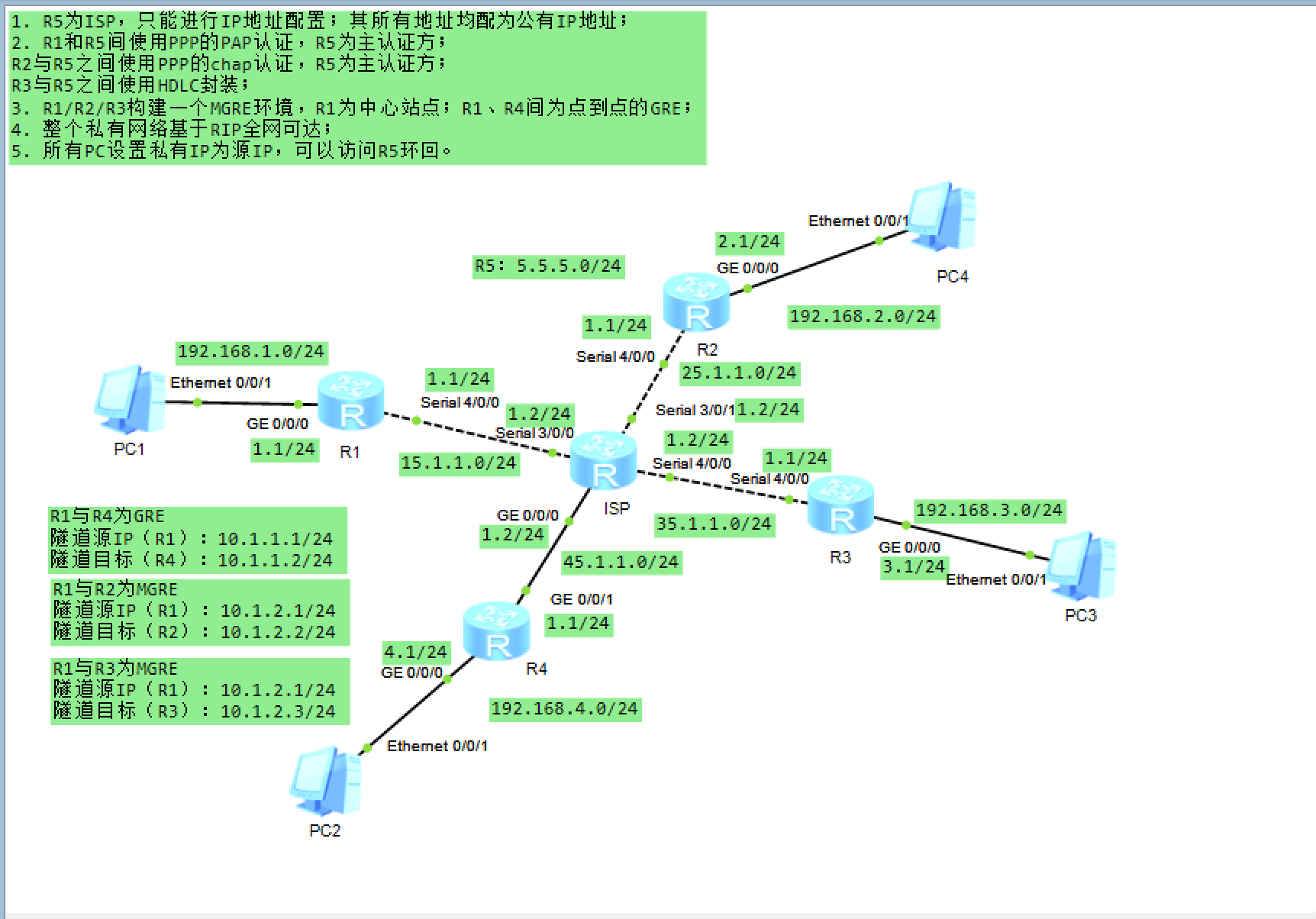
一、实验拓扑图
二、实验需求
-
R5为ISP,只能进行IP地址配置;其所有地址均配为公有IP地址;
-
R1和R5间使用PPP的PAP认证,R5为主认证方;
R2与R5之间使用PPP的chap认证,R5为主认证方;
R3与R5之间使用HDLC封装;
-
R1/R2/R3构建一个MGRE环境,R1为中心站点;R1、R4间为点到点的GRE;
-
整个私有网络基于RIP全网可达;
-
所有PC设置私有IP为源IP,可以访问R5环回。
三、实验思路
1、配置IP及环回口;
2、配置缺省路由,使公网能互通;
3、R1和R5之间使用PPP的PAP认证,R5为主认证方;
4、R2和R5之间使用PPP的CHAP认证,R5为主认证方;
5、R3与R5之间使用HDLC封装;
6、 构建MGRE、GRE环境;
7、 整个私有网络基于RIP全网可达;
8、所有PC设置私有IP为源IP,可以访问R5环回。----做easy IP
四、实验步骤
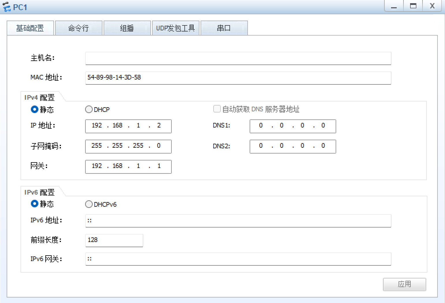
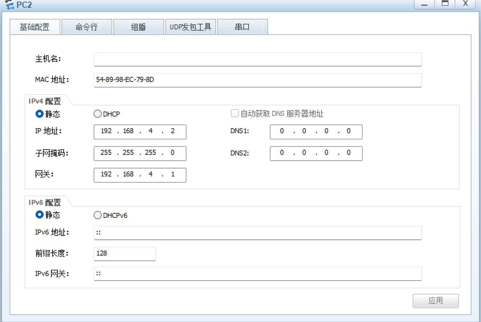
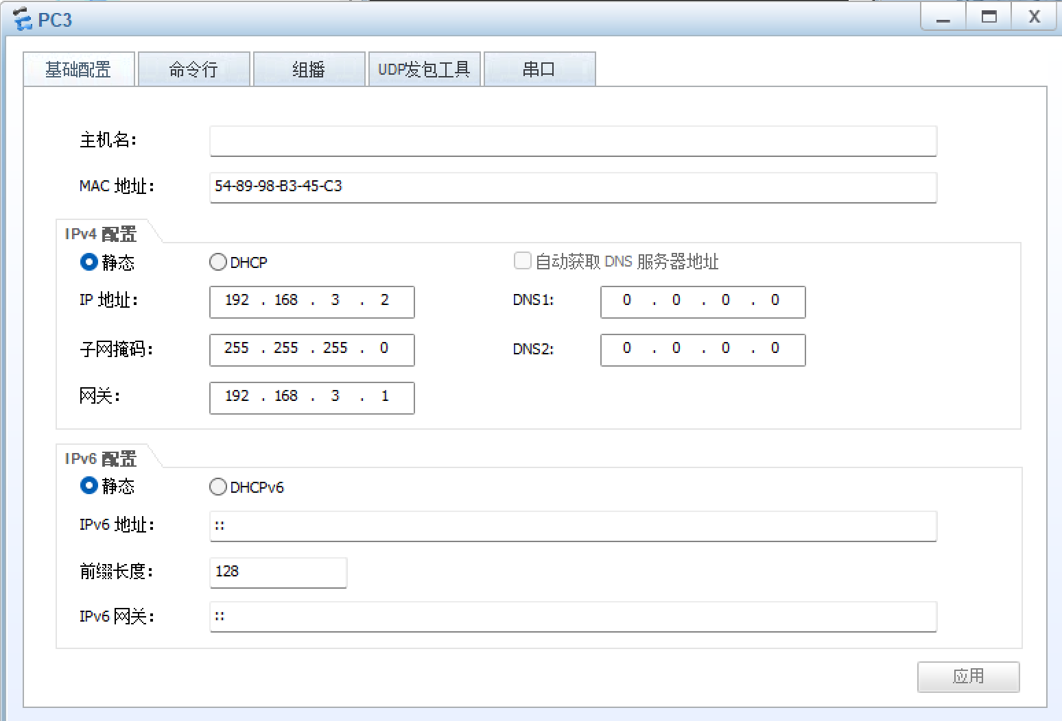
1、配IP
PC1
PC2
PC3
PC4
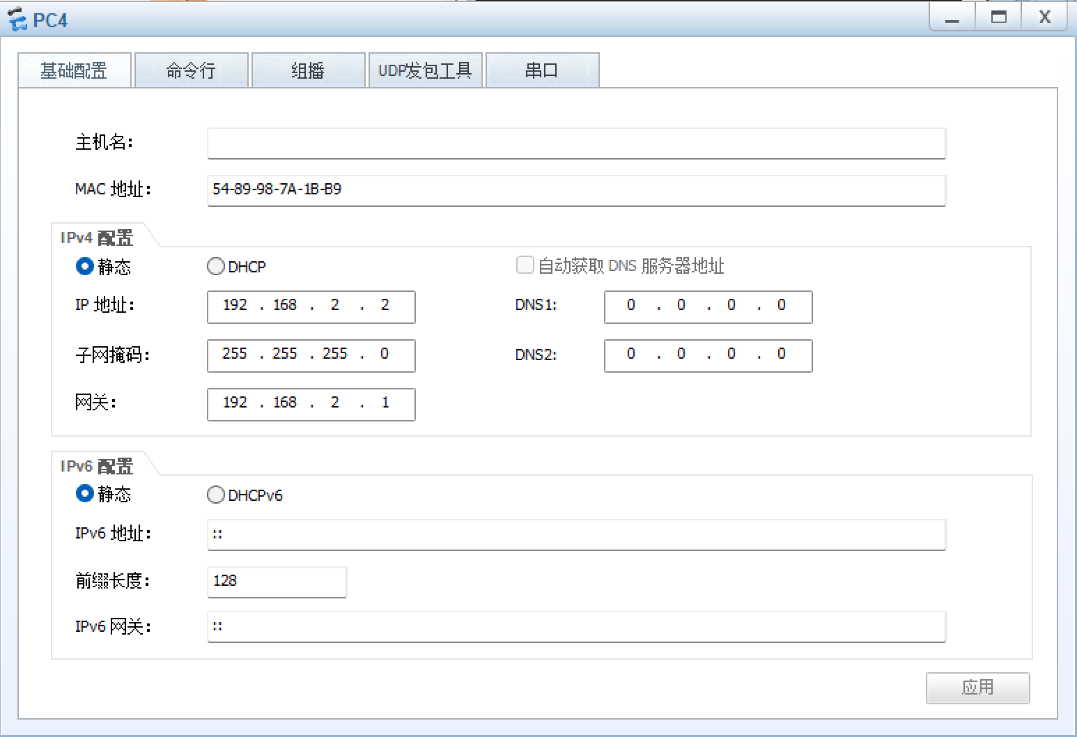
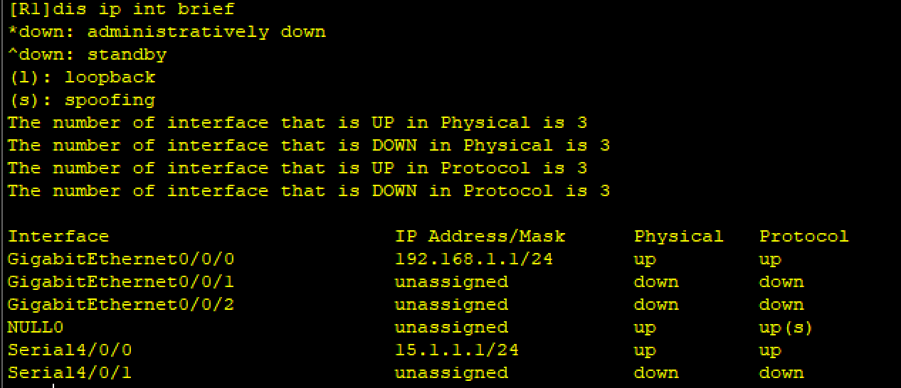
R1
R1int g0/0/0
R1-GigabitEthernet0/0/0ip add 192.168.1.1 24
R1-GigabitEthernet0/0/0int s4/0/0
R1-Serial4/0/0ip add 15.1.1.1 24
查看:
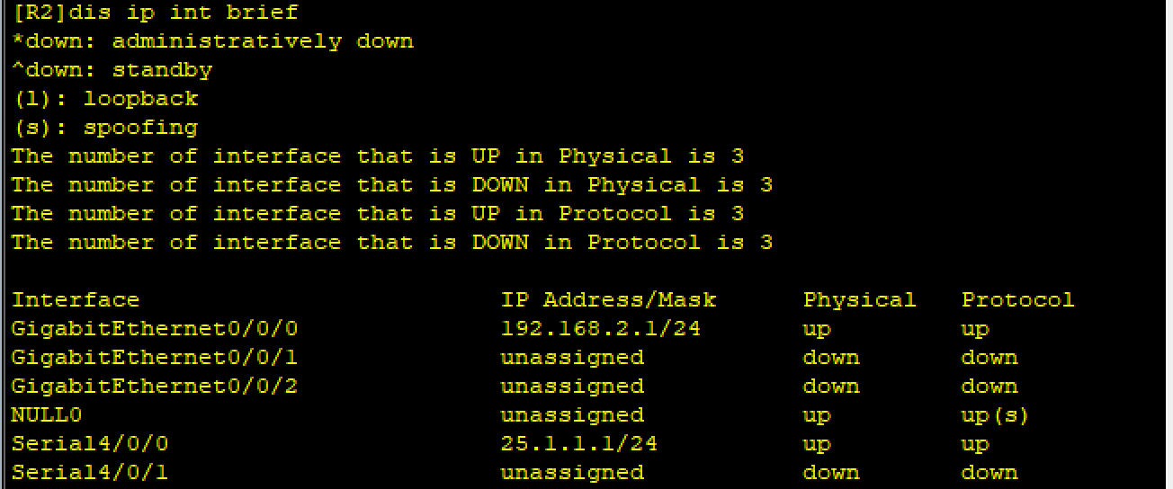
R2
R2int g0/0/0
R2-GigabitEthernet0/0/0ip add 192.168.2.1 24
R2-GigabitEthernet0/0/0int s4/0/0
R2-Serial4/0/0ip add 25.1.1.1 24
查看:
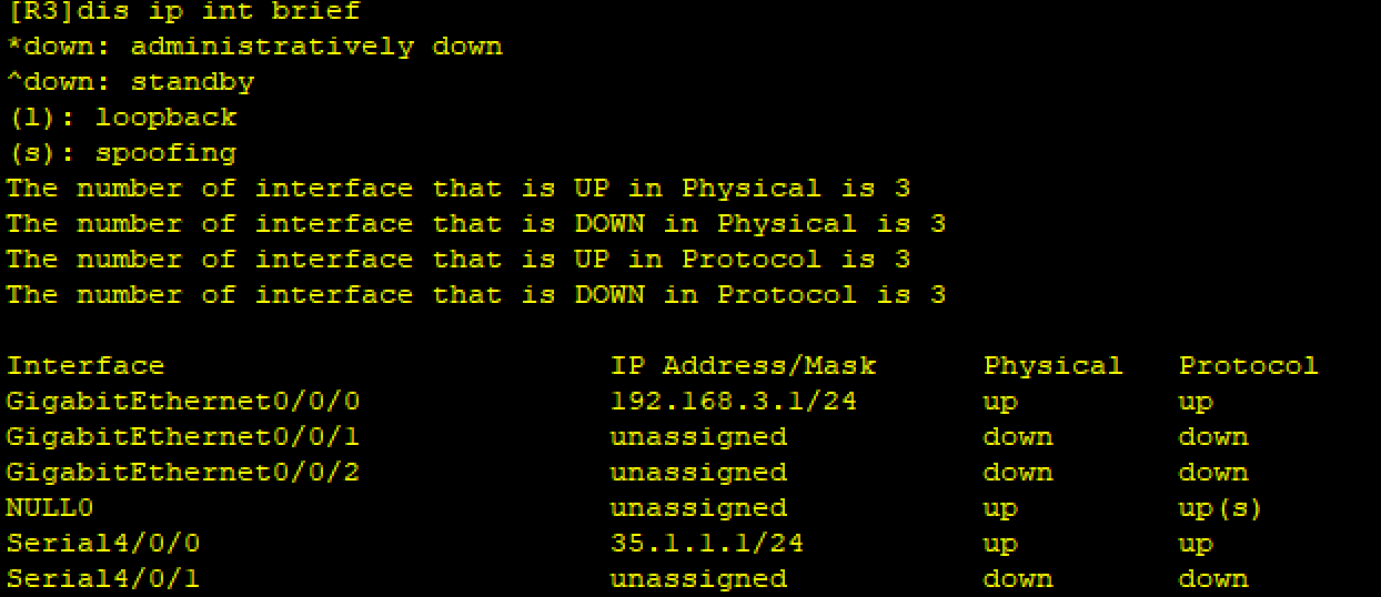
R3
R3int g0/0/0
R3-GigabitEthernet0/0/0ip add 192.168.3.1 24
R3-GigabitEthernet0/0/0int s4/0/0
R3-Serial4/0/0ip add 35.1.1.1 24
查看:
R4
R4int g0/0/0
R4-GigabitEthernet0/0/0ip add 192.168.4.1 24
R4-GigabitEthernet0/0/0int g0/0/1
R4-GigabitEthernet0/0/1ip add 45.1.1.1 24
查看:

R5
R5int g0/0/0
R5-GigabitEthernet0/0/0ip add 45.1.1.2 24
R5int s4/0/0
R5-Serial4/0/0ip add 35.1.1.2 24
R5-Serial4/0/0int s3/0/0
R5-Serial3/0/0ip add 15.1.1.2 24
R5-Serial3/0/0int s3/0/1
R5-Serial3/0/1ip add 25.1.1.2 24
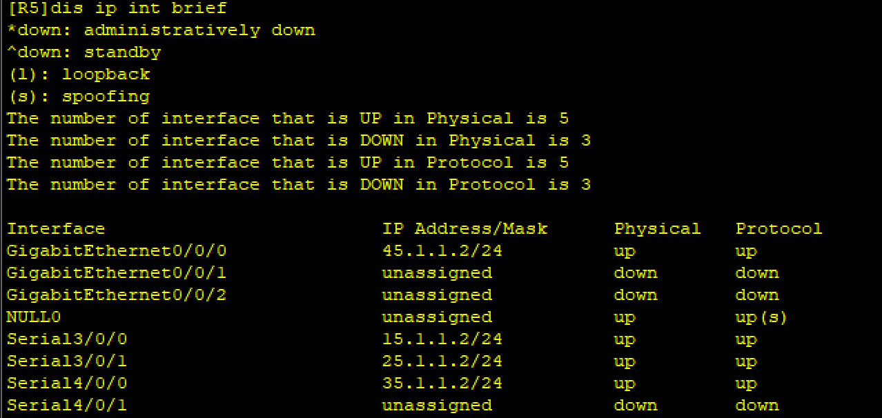
查看:
2、配环回口
R5
R5int l 0
R5-LoopBack0ip add 5.5.5.5 24
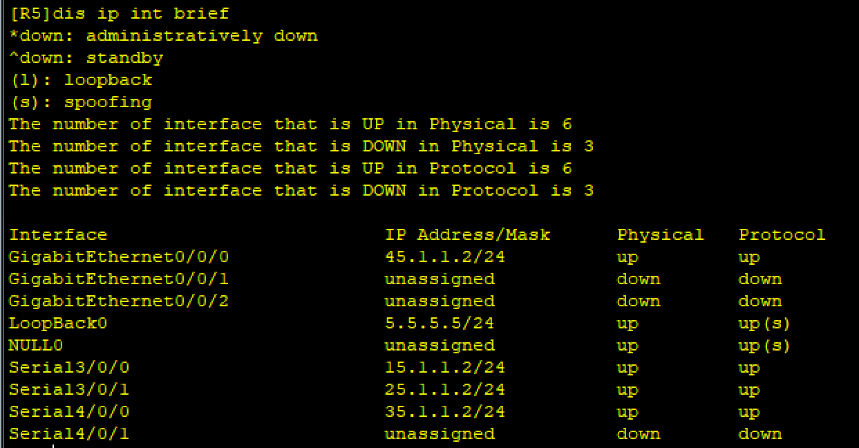
查看:
3、配缺省
R1
R1ip route-static 0.0.0.0 0 15.1.1.2
R2
R2ip route-static 0.0.0.0 0 25.1.1.2
R3
R3ip route-static 0.0.0.0 0 35.1.1.2
R4
R4ip route-static 0.0.0.0 0 45.1.1.2
4、使R1和R5(ISP)之间使用PPP的PAP认证,并且R5为主认证方

可以看到华为设备默认采用了PPP协议
主认证方配置(R5):
ISPaaa
ISP-aaalocal-user wangdaye password cipher 123456
ISP-aaalocal-user wangdaye service-type ppp----进入aaa,创建认证使用的用户和密码
ISP-aaaq
ISPint s 3/0/0
ISP-Serial3/0/0ppp authentication-mode pap----配置PAP
被认证方配置(R1):
R1int s4/0/0
R1-Serial4/0/0ppp pap local-user wangdaye password cipher 123456
测试:
断开ISP(R5)会话,重启启动认证(因为R5已经建立了会话连接):
ISPint s3/0/0
ISP-Serial3/0/0shutdown
ISP-Serial3/0/0undo shutdown
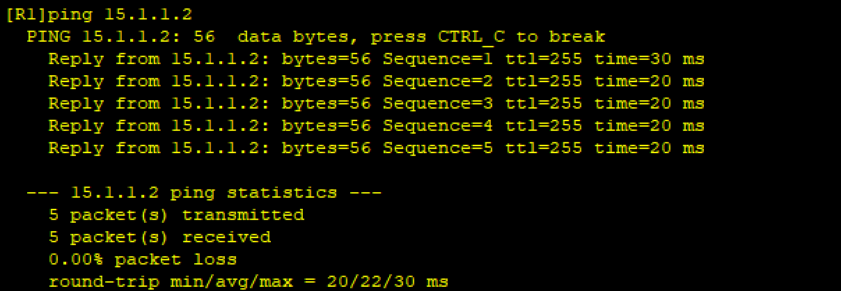
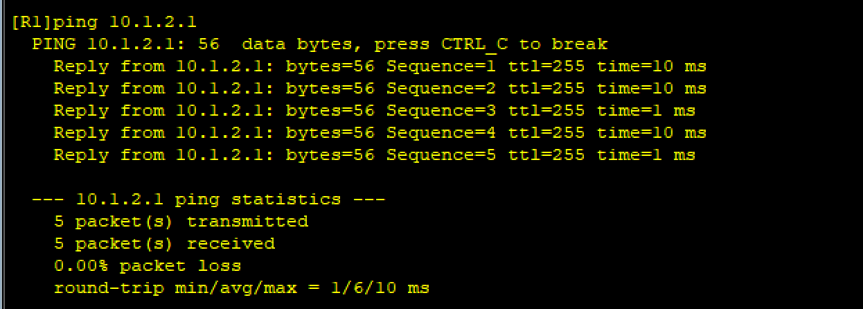
ping 15.1.1.1测试:
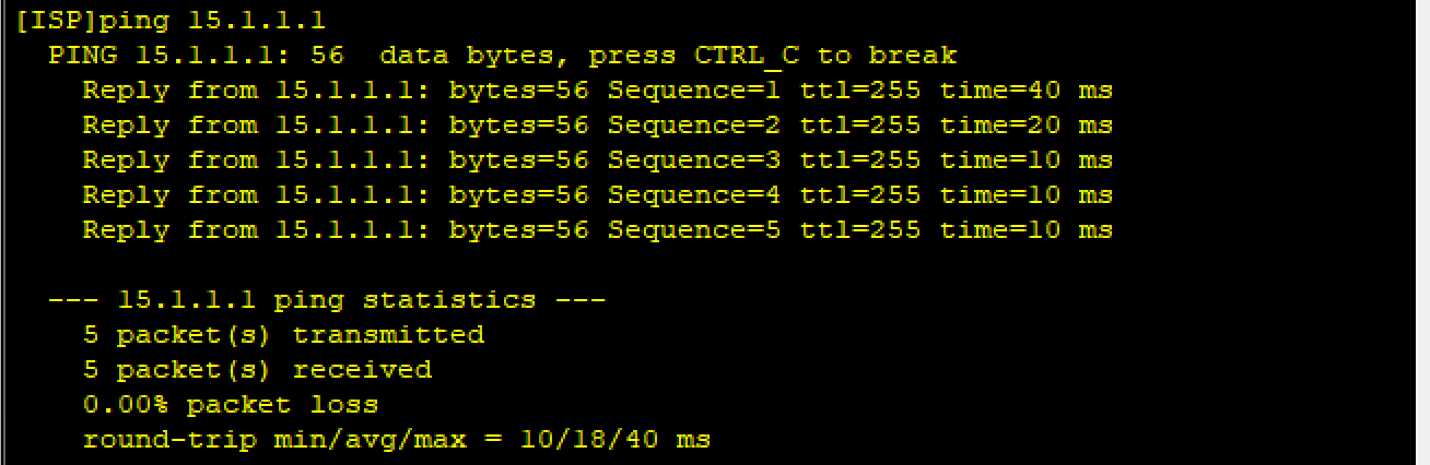
ping 15.1.1.2测试:
5、使R2和R5之间使用PPP的CHAP认证,R5为主认证方
主认证方的配置:
R5因为刚刚已经创建了认证使用的用户名和密码,所以不用再次创建
ISPint s3/0/1
ISP-Serial3/0/1ppp authentication-mode chap
被认证方的配置:
R2int s4/0/0
R2-Serial4/0/0ppp chap user wangdaye
R2-Serial4/0/0ppp chap password cipher 123456
测试:
ISPint s3/0/1
ISP-Serial3/0/1shutdown
ISP-Serial3/0/1undo shutdown
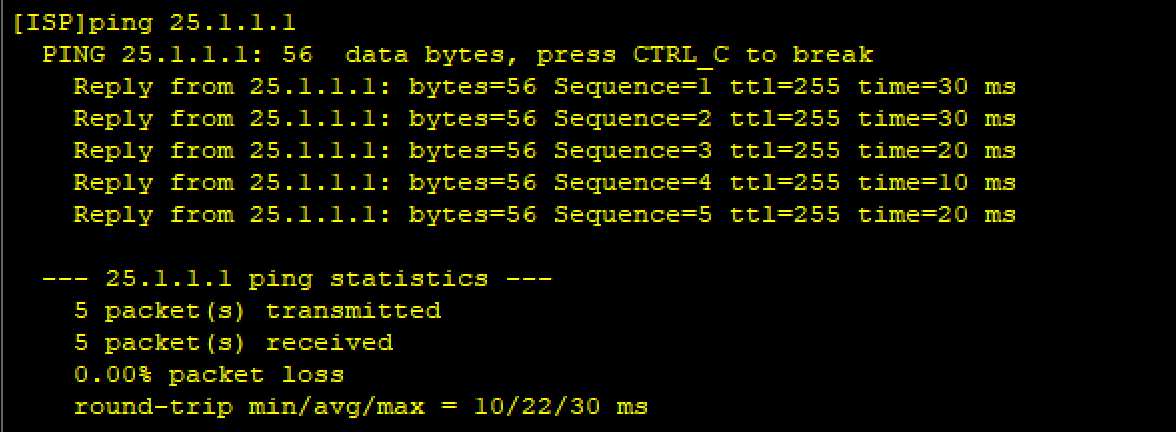
ping 25.1.1.1测试:
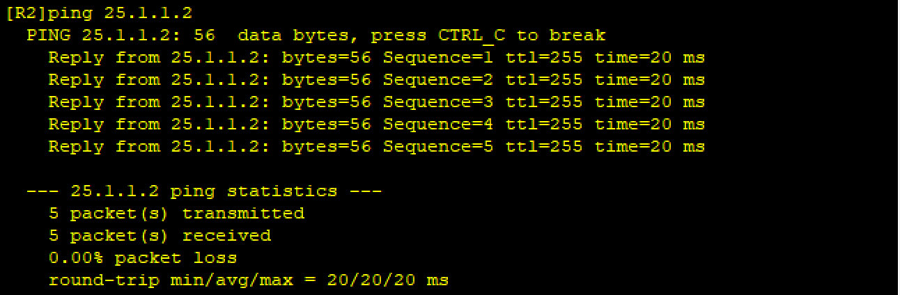
ping 25.1.1.2测试:
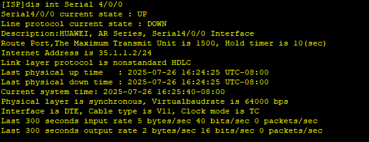
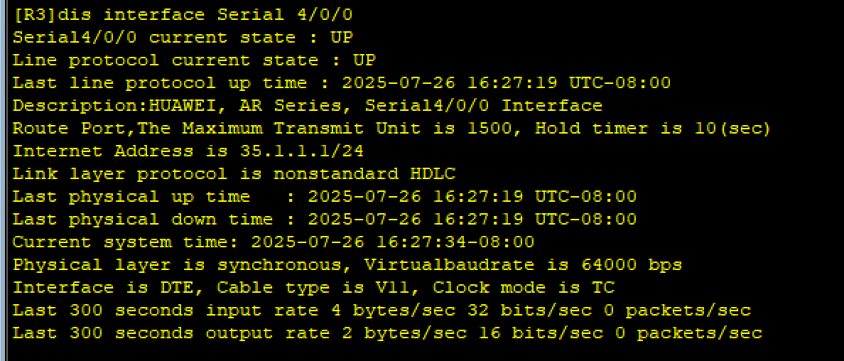
6、让R3与R5之间使用HDLC封装
只需修改双方接口的协议即可,两边接口必须相同才能通信,否则不会进行通信
R5(ISP)
ISPint s4/0/0
ISP-Serial4/0/0link-protocol hdlc
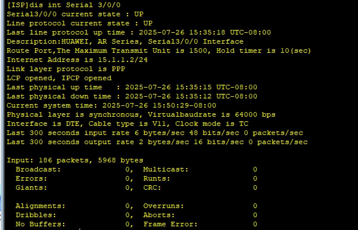
查看:

R3
R3int s4/0/0
R3-Serial4/0/0link-protocol hdlc
查看:

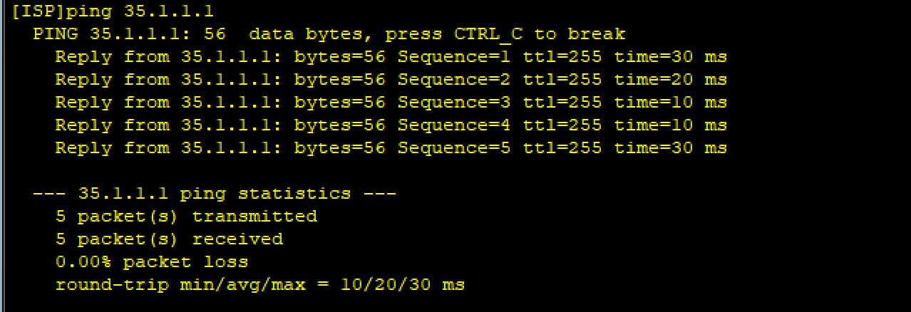
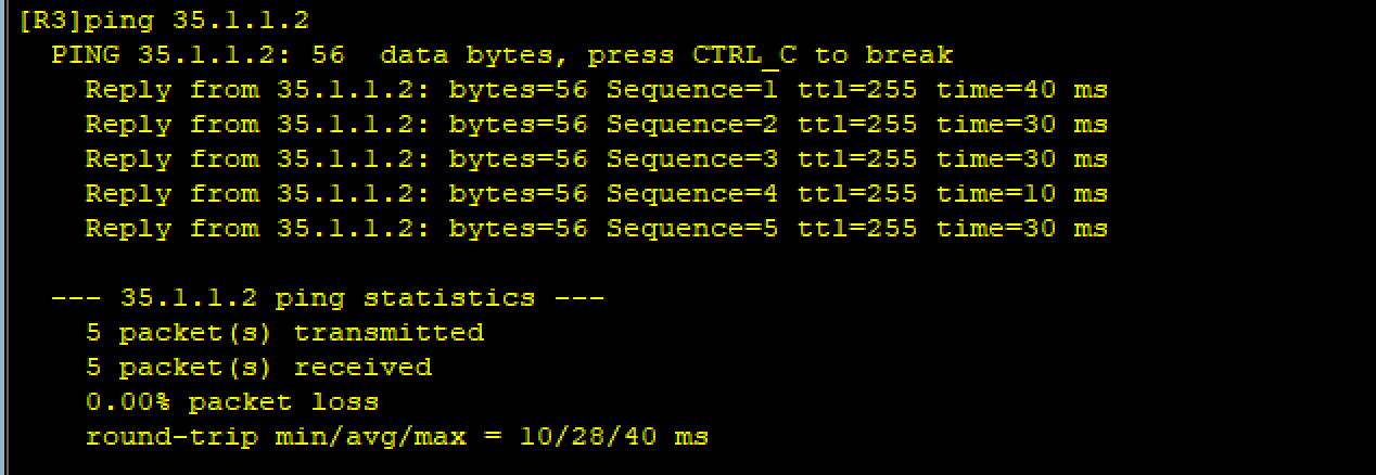
测试:
7、 构建MGRE、GRE环境
(1)R1/R2/R3构建一个MGRE环境,R1为中心站点
R1/R2/R3MGRE配置使用10.1.2.0/24网段
配置总部与分部之间的隧道:
R1(中心站点,2.1/24)
R1int Tunnel 0/0/0----创建隧道接口
R1-Tunnel0/0/0ip add 10.1.2.1 24----配置IP地址
R1-Tunnel0/0/0tunnel-protocol gre p2mp ----选择配置方法
R1-Tunnel0/0/0source 15.1.1.1----定义源IP地址(也可以直接用接口来代替)
R2(2.2/24)
R2int Tunnel 0/0/0
R2-Tunnel0/0/0ip add 10.1.2.2 24
R2-Tunnel0/0/0tunnel-protocol gre p2mp
R2-Tunnel0/0/0source 25.1.1.1
R3(2.3/24)
R3int Tunnel 0/0/0
R3-Tunnel0/0/0ip add 10.1.2.3 24
R3-Tunnel0/0/0tunnel-protocol gre p2mp
R3-Tunnel0/0/0source 35.1.1.1
NHRP的配置:
R1(中心站点)
R1int Tunnel 0/0/0
R1-Tunnel0/0/0nhrp network-id 100----创建NHRP域,获取目标IP
R2
R2-Tunnel0/0/0nhrp network-id 100
R2-Tunnel0/0/0nhrp entry 10.1.2.1 15.1.1.1 register
R3
R3-Tunnel0/0/0nhrp network-id 100
R3-Tunnel0/0/0nhrp entry 10.1.2.1 15.1.1.1 register
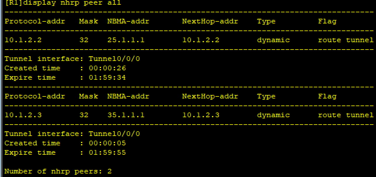
查看NHRP注册信息:
(2)R1、R4间为点到点的GRE
R1和R4之间GRE配置使用10.1.1.0/24网段
R1(10.1.1.1/24)
R1int Tunnel 0/0/1
R1-Tunnel0/0/1ip add 10.1.1.1 24
R1-Tunnel0/0/1tunnel-protocol gre
R1-Tunnel0/0/1source 15.1.1.1
R1-Tunnel0/0/1destination 45.1.1.1----这里的source和destination是真实的物理线路
R4(10.1.1.2/24)
R4int Tunnel 0/0/1
R4-Tunnel0/0/1ip add 10.1.1.2 24
R4-Tunnel0/0/1tunnel-protocol gre
R4-Tunnel0/0/1source 45.1.1.1
R4-Tunnel0/0/1destination 15.1.1.1----这里不要写成description
8、 整个私有网络基于RIP全网可达
(1)MGRE
R1
R1rip 1
R1-rip-1version 2
R1-rip-1undo summary
R1-rip-1network 192.168.1.0
R1-rip-1network 10.0.0.0----RIP要求宣告主类网络地址
R2
R2rip 1
R2-rip-1version 2
R2-rip-1undo summary
R2-rip-1network 192.168.2.0
R2-rip-1network 10.0.0.0
R3
R3rip 1
R3-rip-1version 2
R3-rip-1undo summary
R3-rip-1network 192.168.3.0
R3-rip-1network 10.0.0.0
开启伪广播
当我们配置好了过后我们发现除了R1有路由外,R2和R3都没有路由,这是为什么呢? 这是因为我们的MGRE构建出来这个网络类似一个NBMA网络,它是不支持广播和组播的。
解决方法:在中心上开启伪广播,目的:告诉分支站点,中心站点及其他分支站点的私网网段信息。
R1interface Tunnel 0/0/0
R1-Tunnel0/0/0nhrp entry multicast dynamic
关闭水平分割
发现其他路由表都只有R1的路由表中的信息,这是因为华为设备默认RIP的环回机制----水平分割导致的,我们只需要关闭它即可。
R1-Tunnel0/0/0undo rip split-horizon
R2-Tunnel0/0/0undo rip split-horizon
R3-Tunnel0/0/0undo rip split-horizon
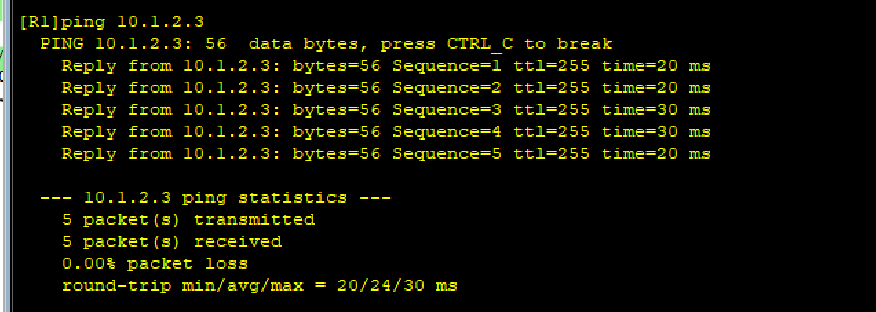
查看:
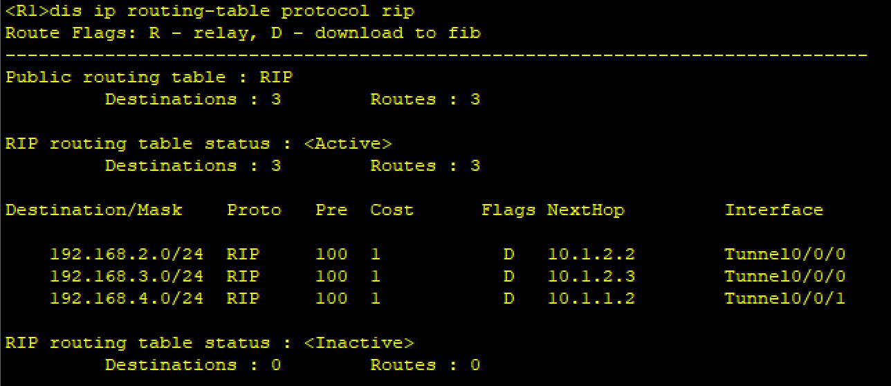
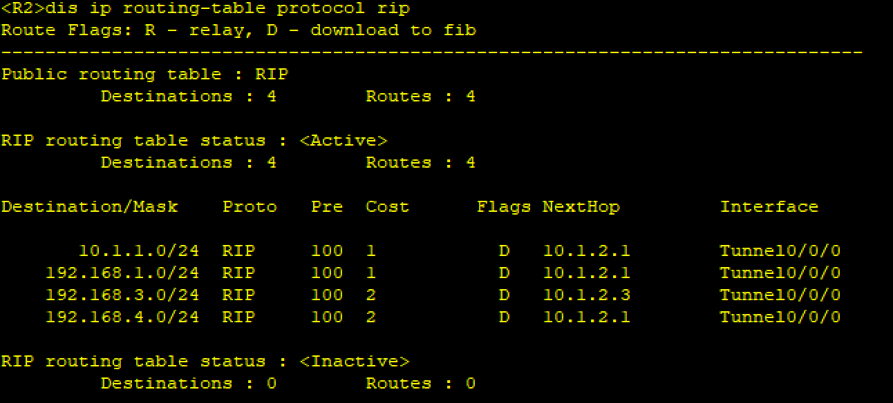

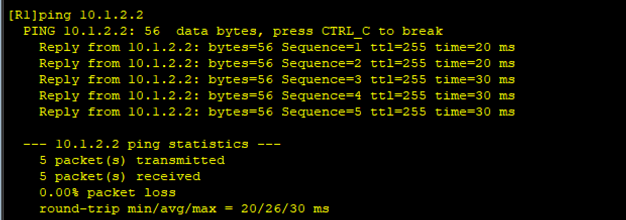
测试:
(2)GRE
R1在MGRE时已经配置RIP,R4的主类网络地址也已宣告,如果R4是其他的主类网络地址则需宣告。
R4
R4rip 1
R4-rip-1version 2
R4-rip-1undo summary
R4-rip-1network 192.168.4.0
R4-rip-1network 10.0.0.0
注:这里只宣告私有网段
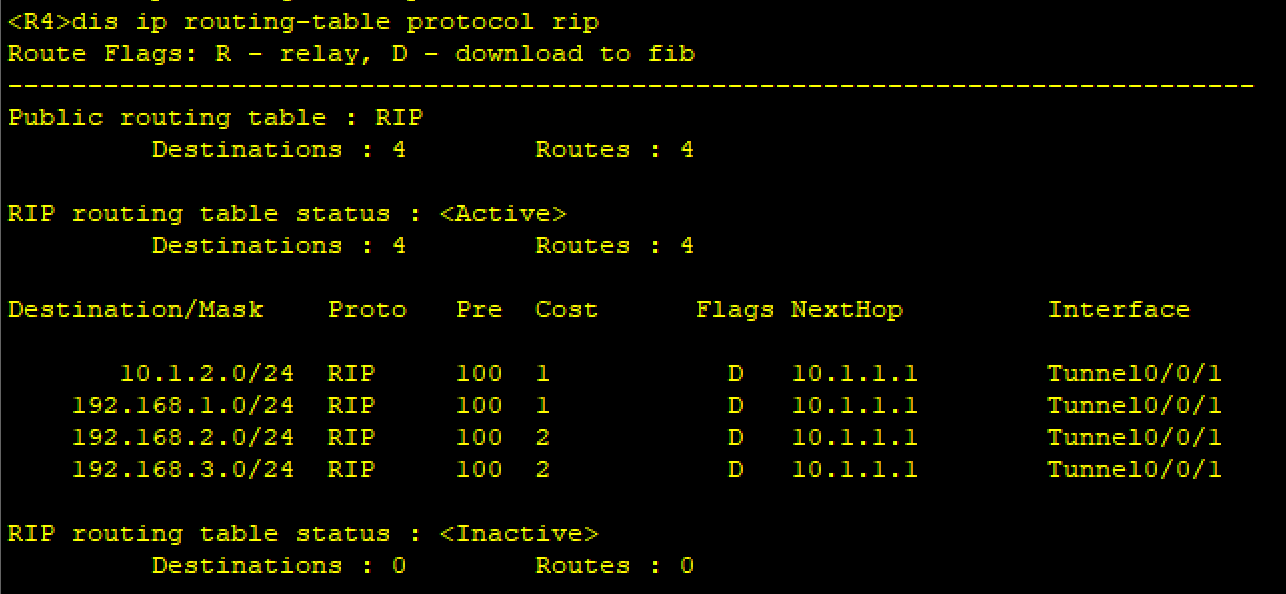
查看:
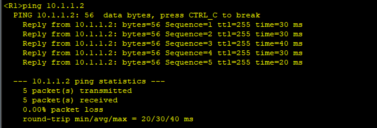
测试:
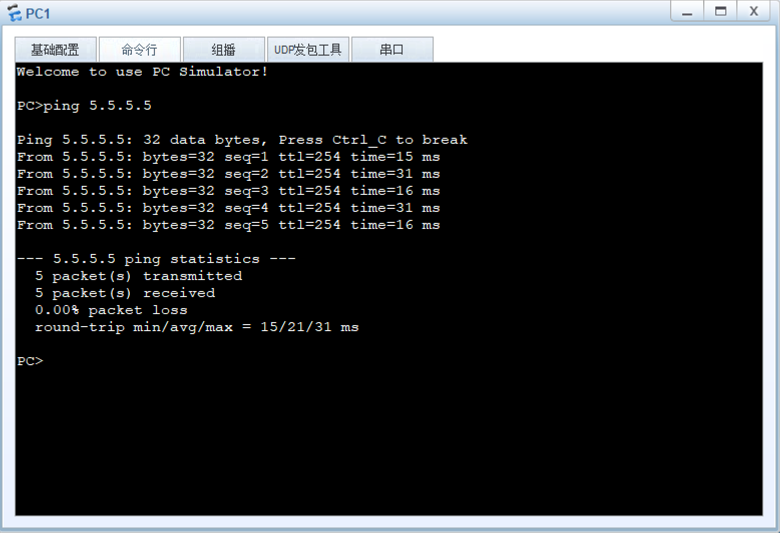
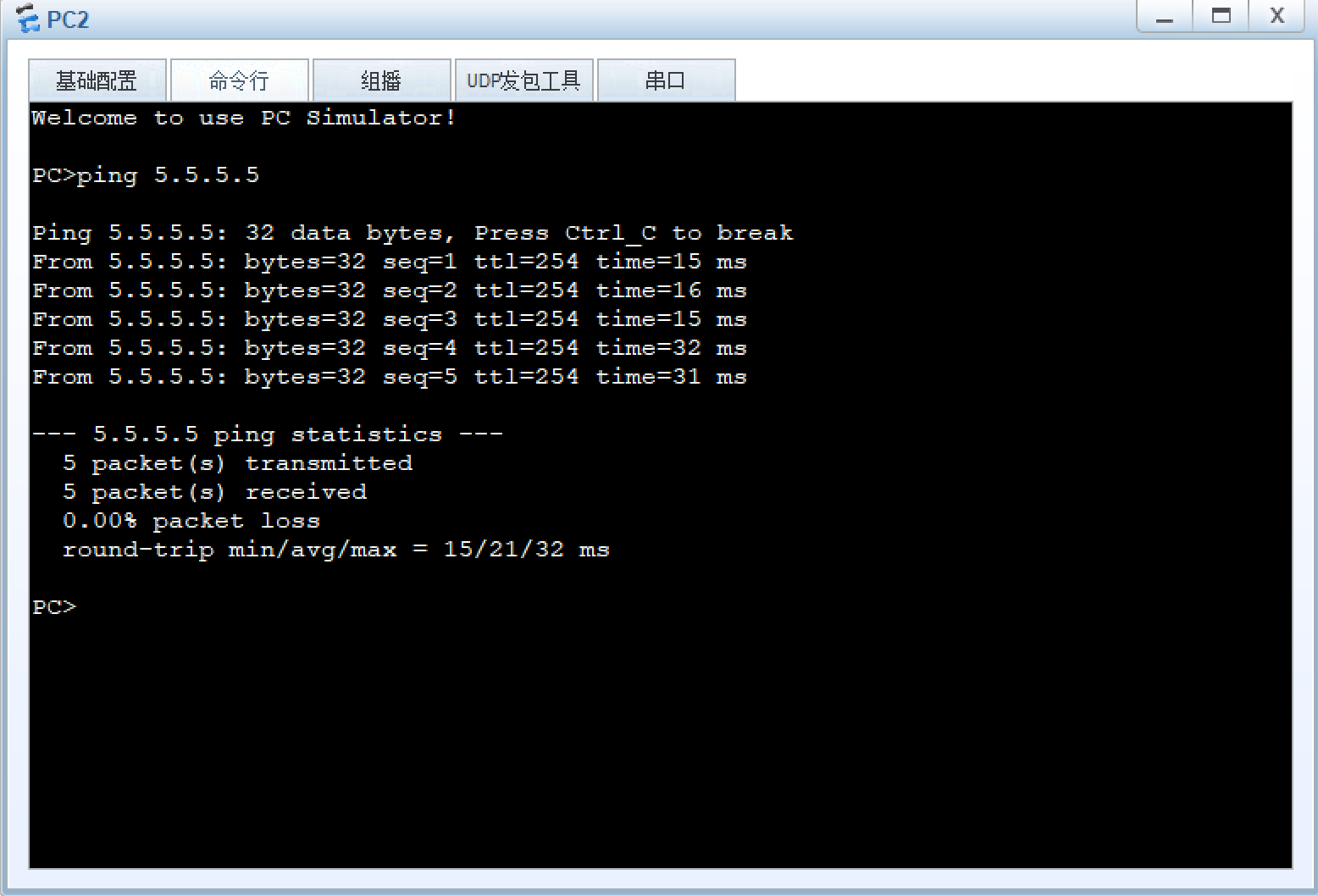
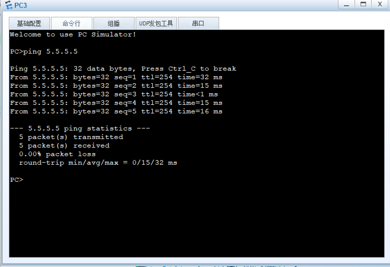
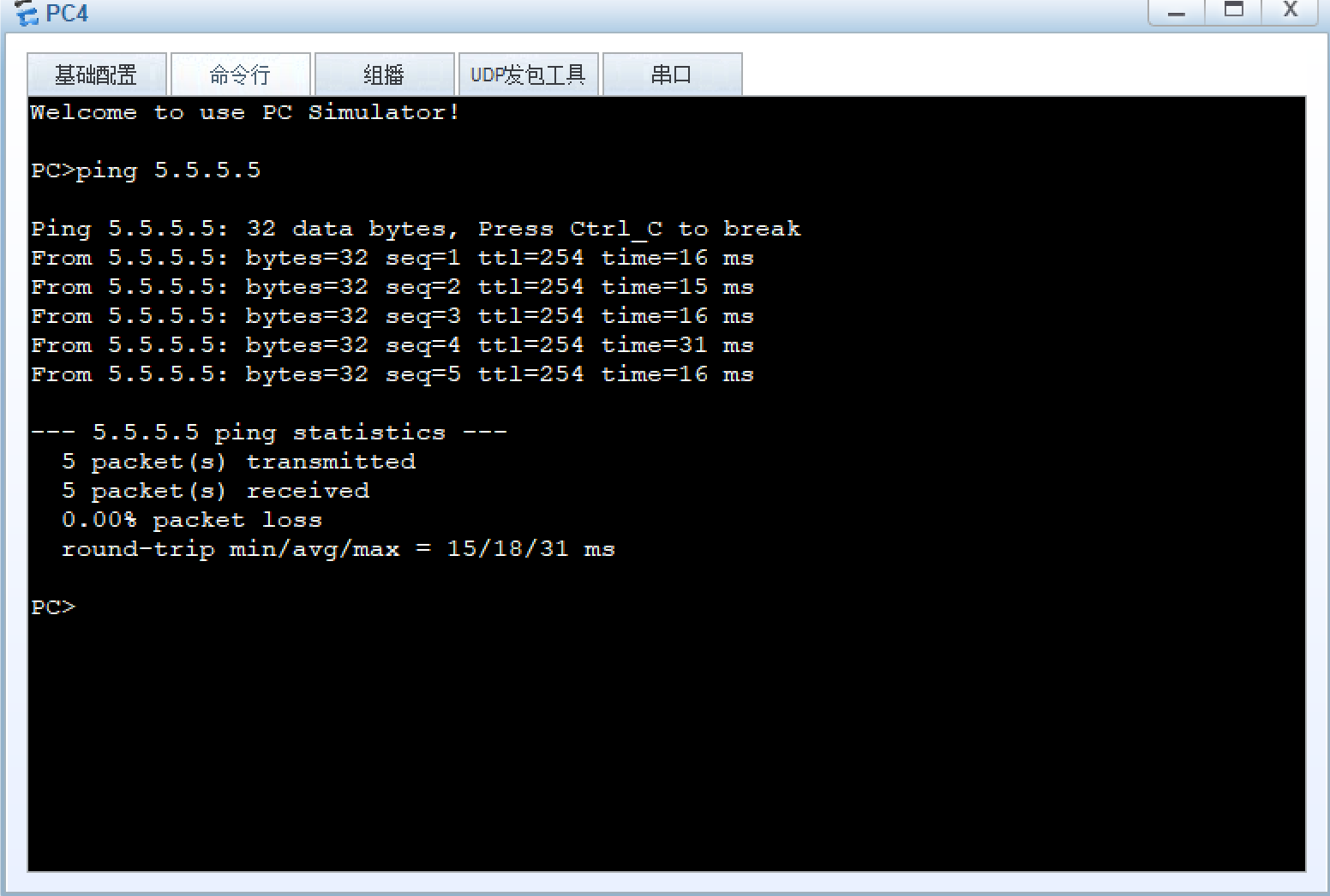
9、所有PC设置私有IP为源IP,可以访问R5环回
R1
R1acl 2000
R1-acl-basic-2000rule permit source 192.168.1.0 0.0.0.255
R1int s4/0/0
R1-Serial4/0/0nat outbound 2000
R2
R2acl 2000
R2-acl-basic-2000rule permit source 192.168.2.0 0.0.0.255
R2int s4/0/0
R2-Serial4/0/0nat outbound 2000
R3
R3acl 2000
R3-acl-basic-2000rule permit source 192.168.3.0 0.0.0.255
R3int s4/0/0
R3-Serial4/0/0nat outbound 2000
R4
R4acl 2000
R4-acl-basic-2000rule permit source 192.168.4.0 0.0.0.255
R4int g0/0/1
R4-GigabitEthernet0/0/1nat outbound 2000
测试: