GRE及MGRE应用综合实验
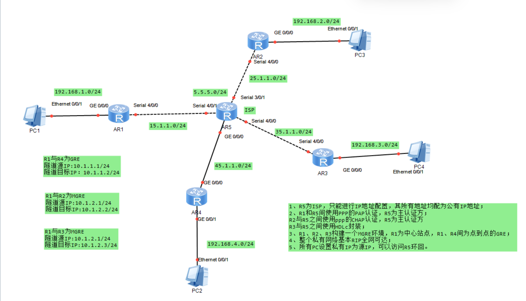
一、实验拓扑
二、实验需求
1、R5为ISP,只能进行IP地址配置,其所有地址均配为公有IP地址;
2、R1和R5间使用PPP的PAP认证,R5为主认证方;
R2与R5之间使用ppp的CHAP认证,R5为主认证方
R3与R5之间使用HDLc封装;
3、R1、R2、R3构建一个MGRE环境,R1为中心站点,R1、R4间为点到点的GRE;
4、整个私有网络基本RIP全网可达;
5、所有PC设置私有IP为源IP,可以访问R5环回。
三、实验思路
1.根据划分的网段,为所有PC机以及路由器接口配置IP地址;
2为R1和R5间配置PPP的PAP认证,R5为主认证方;
3.R2与R5之间配置ppp的CHAP认证,R5为主认证方;
4.配置R3与R5之间使用HDLC封装 ;
5.在R1~R5上配置默认路由使公网互通;
6.建立R1、R4间点到点的GRE;
7.将R1、R2、R3构建一个MGRE环境,R1为中心站点;
8..配置rip来传递私网路由。
四、实验步骤
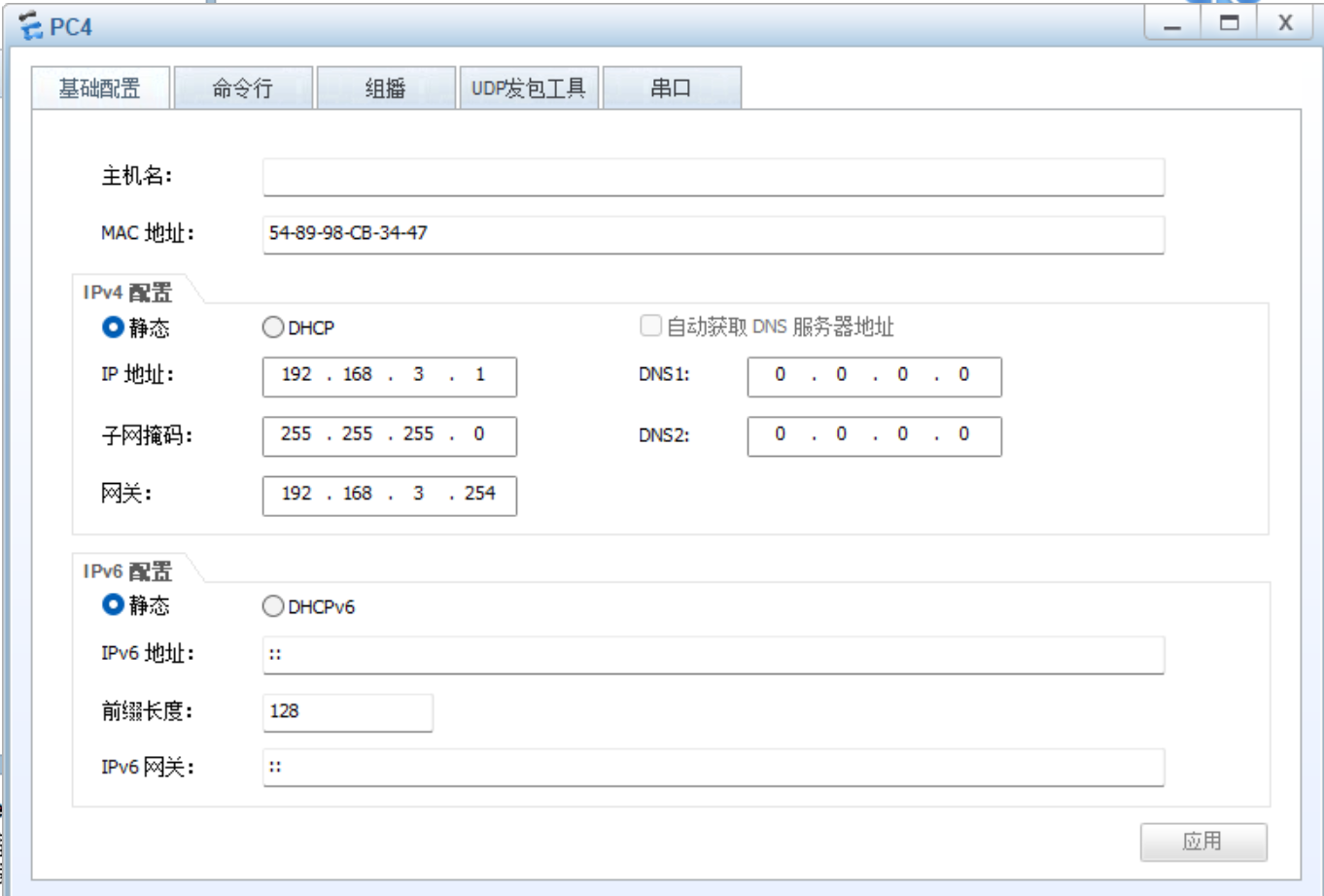
1.为所有PC机以及路由器接口配置IP地址
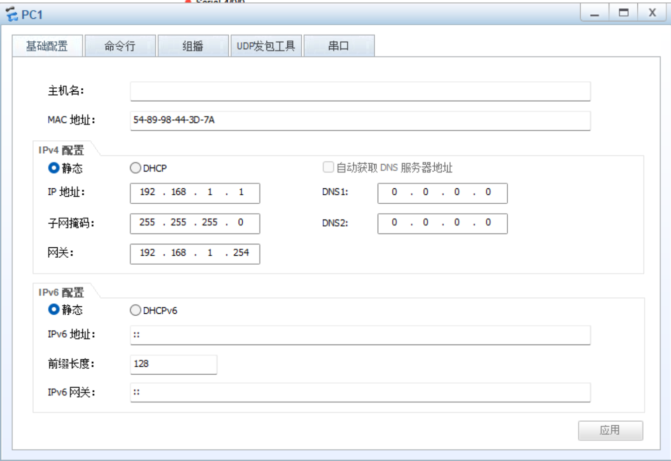
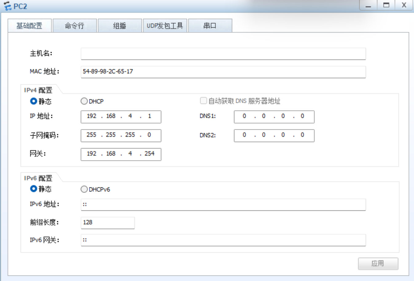
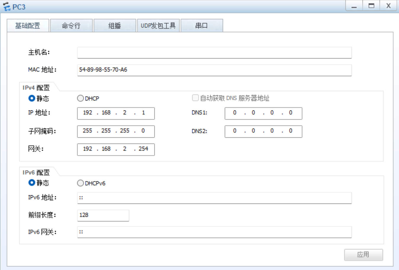
(1)PC机
(2)路由器接口
R1:
R1int g0/0/0
R1-GigabitEthernet0/0/0ip add 192.168.1.254 24
Jul 25 2025 22:18:48-08:00 R1 %%01IFNET/4/LINK_STATE(l)0:The line protocol IP
on the interface GigabitEthernet0/0/0 has entered the UP state.
R1-GigabitEthernet0/0/0int s4/0/0
R1-Serial4/0/0ip add 15.1.1.1 24
R2:
R2int g0/0/0
R2-GigabitEthernet0/0/0ip add 192.168.2.254 24
Jul 25 2025 22:24:42-08:00 R2 %%01IFNET/4/LINK_STATE(l)0:The line protocol IP
on the interface GigabitEthernet0/0/0 has entered the UP state.
R2-GigabitEthernet0/0/0int s4/0/0
R2-Serial4/0/0ip add 25.1.1.1 24
R3:
R3int g0/0/0
R3-GigabitEthernet0/0/0ip add 192.168.3.254 24
Jul 25 2025 22:35:19-08:00 R3 %%01IFNET/4/LINK_STATE(l)0:The line protocol IP
on the interface GigabitEthernet0/0/0 has entered the UP state.
R3-GigabitEthernet0/0/0int s4/0/0
R3-Serial4/0/0ip add 35.1.1.1 24
R4:
R4int g0/0/1
R4-GigabitEthernet0/0/1ip add 192.168.4.254 24
R4-GigabitEthernet0/0/1
Jul 25 2025 22:37:13-08:00 R4 %%01IFNET/4/LINK_STATE(l)0:The line protocol IP
on the interface GigabitEthernet0/0/1 has entered the UP state.
R4-GigabitEthernet0/0/1int g0/0/0
R4-GigabitEthernet0/0/0ip add 45.1.1.1 24
R5:
R5int g0/0/0
R5-GigabitEthernet0/0/0ip add 45.1.1.2 24
R5-GigabitEthernet0/0/0
Jul 25 2025 22:41:37-08:00 R5 %%01IFNET/4/LINK_STATE(l)0:The line protocol IP
on the interface GigabitEthernet0/0/0 has entered the UP state.
R5-GigabitEthernet0/0/0int s4/0/1
R5-Serial4/0/1ip add 15.1.1.2 24
R5-Serial4/0/1
Jul 25 2025 22:42:30-08:00 R5 %%01IFNET/4/LINK_STATE(l)1:The line protocol PPP
IPCP on the interface Serial4/0/1 has entered the UP state.
R5-Serial4/0/1int s3/0/1
R5-Serial3/0/1ip add 25.1.1.2 24
R5-Serial3/0/1
Jul 25 2025 22:44:07-08:00 R5 %%01IFNET/4/LINK_STATE(l)2:The line protocol PPP
IPCP on the interface Serial3/0/1 has entered the UP state.
R5-Serial3/0/1int s4/0/0
R5-Serial4/0/0ip add 35.1.1.2 24
R5环回口:
R5int l0
R5-LoopBack0ip add 5.5.5.1 24
- 、R1和R5间使用PPP的PAP认证,R5为主认证方
R5:
R5aaa
R5-aaalocal-user wangdaye password cipher wdy12345
Info: Add a new user.
R5-aaalocal-user wangdaye service-type ppp
R5-aaaq
R5int s4/0/1
R5-Serial4/0/1ppp authentication-mode PAP
R5-Serial4/0/1link-protocol ppp
R1:
R1int s4/0/0
R1-Serial4/0/0ppp pap local-user wangdaye password cipher wdy12345
3.R2与R5之间使用ppp的CHAP认证,R5为主认证方
R5配置如上一步
R2:
R2int s4/0/0
R2-Serial4/0/0ppp pap local-user wangdaye password cipher wdy12345
4.配置R3与R5之间使用HDLC封装
R3:
R3int s4/0/0
R3-Serial4/0/0link-protocol HDLC
R5:
R5int s4/0/0
R5-Serial4/0/0link-protocol HDLC
- 在R1~R5上配置默认路由使公网互通
R1:
R1ip route-static 0.0.0.0 0 15.1.1.2
R2:
R2ip route-static 0.0.0.0 0 25.1.1.2
R3:
R3ip route-static 0.0.0.0 0 35.1.1.2
R5:
R4ip route-static 0.0.0.0 0 45.1.1.2
- 建立R1、R4间点到点的GRE
(1)在R1上创建Tunnel口,模式为GRE,源地址和目的地址为本端公网地址和对端公网地址
R1int tunnel0/0/0
R1-Tunnel0/0/0tunnel-protocol gre
R1-Tunnel0/0/0ip add 10.1.1.1 24
R1-Tunnel0/0/0source 15.1.1.1
R1-Tunnel0/0/0destination 45.1.1.1
(2)在R4上创建Tunnel口,模式为GRE,源地址和目的地址为本端公网地址和对端公网地址
R4int tunnel0/0/0
R4-Tunnel0/0/0tunnel-protocol gre
R4-Tunnel0/0/0ip add 10.1.1.2 24
R4-Tunnel0/0/0source 45.1.1.1
R4-Tunnel0/0/0destination 15.1.1.1
7.将R1、R2、R3构建一个MGRE环境,R1为中心站点
(1)配置总部与分部之间的隧道-MGRE VPN
R1:
R1int tunnel0/0/1
R1-Tunnel0/0/1tunnel-protocol gre p2mp
R1-Tunnel0/0/1ip add 10.1.2.1 24
R1-Tunnel0/0/1source 15.1.1.1
R2:
R2int tunnel0/0/1
R2-Tunnel0/0/1tunnel-protocol gre ?
p2mp Point to multi-point GRE mode
<cr> Please press ENTER to execute command
R2-Tunnel0/0/1tunnel-protocol gre p2mp
R2-Tunnel0/0/1ip add 10.1.2.2 24
R2-Tunnel0/0/1source 25.1.1.1
R3:
R3int tunnel0/0/1
R3-Tunnel0/0/1tunnel-protocol gre p2mp
R3-Tunnel0/0/1ip add 10.1.2.3 24
R3-Tunnel0/0/1source 35.1.1.1
(2)NHRP的配置
中心站点配置:
R1:
R1int tunnel0/0/1
R1-Tunnel0/0/1nhrp network-id 100
分支站点配置:
R2:
R2int tunnel 0/0/1
R2-Tunnel0/0/1nhrp network-id 100
R2-Tunnel0/0/1nhrp entry 10.1.2.1 15.1.1.1 register
R3:
R3int tunnel0/0/1
R3-Tunnel0/0/1nhrp network-id 100
R3-Tunnel0/0/1nhrp entry 10.1.2.1 15.1.1.1
8.配置rip来传递私网路由
R1:
R1rip 1
R1-rip-1undo summary
R1-rip-1version 2
R1-rip-1network 192.168.1.0
R1-rip-1network 10.0.0.0
R2:
R2rip 1
R2-rip-1undo summary
R2-rip-1version 2
R2-rip-1network 192.168.2.0
R2-rip-1network 10.0.0.0
R3:
R3rip 1
R3-rip-1undo summary
R3-rip-1version 2
R3-rip-1network 192.168.4.0
R3-rip-1network 10.0.0.0
R4:
R4rip 1
R4-rip-1undo summary
R4-rip-1version 2
R4-rip-1network 192.168.4.0
R4-rip-1network 10.0.0.0
在 中心上开启伪广播:
R1int tunnel0/0/1
R1-Tunnel0/0/1nhrp entry multicast dynamic
关闭RIP的水平分割机制:
R1-Tunnel0/0/1undo rip split-horizon
R2-Tunnel0/0/1undo rip split-horizon
R3-Tunnel0/0/1undo rip split-horizon
五、实验结果
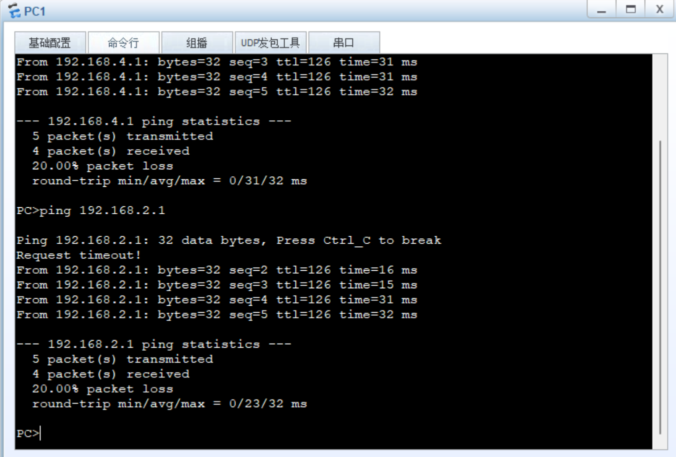 实验成功
实验成功