一、项目目的
本实验旨在通过构建 GRE 及 MGRE 综合网络环境,掌握 VPN 隧道技术在复杂网络中的应用。具体目标包括:熟练配置 GRE 点对点隧道与 MGRE 星型隧道,实现不同子网的私有网络互联;掌握 PPP 协议的 PAP、CHAP 认证及 HDLC 封装,保障链路层数据传输的安全性与兼容性;通过 RIP 路由协议实现私有网络全网可达,并验证私有 IP 通过隧道访问公网的可行性。通过实验深化对 VPN 技术、链路层协议及路由协议协同工作的理解,提升复杂网络环境的设计与部署能力。
二、项目背景
随着企业分支机构地理分散化,跨地域私有网络互联需求日益增长。GRE 与 MGRE 作为常用 VPN 技术,可在公网中构建加密隧道,实现私有数据安全传输。实际场景中,不同链路可能采用 PPP(含认证)或 HDLC 封装,且需通过动态路由协议保障全网可达。本实验模拟真实网络环境,以 R5 作为公网 ISP,R1-R4 为私有网络设备,通过配置不同隧道与链路协议,解决跨网通信、认证加密及私有 IP 访问公网等问题,为企业多分支网络设计提供技术验证。
三、项目拓扑
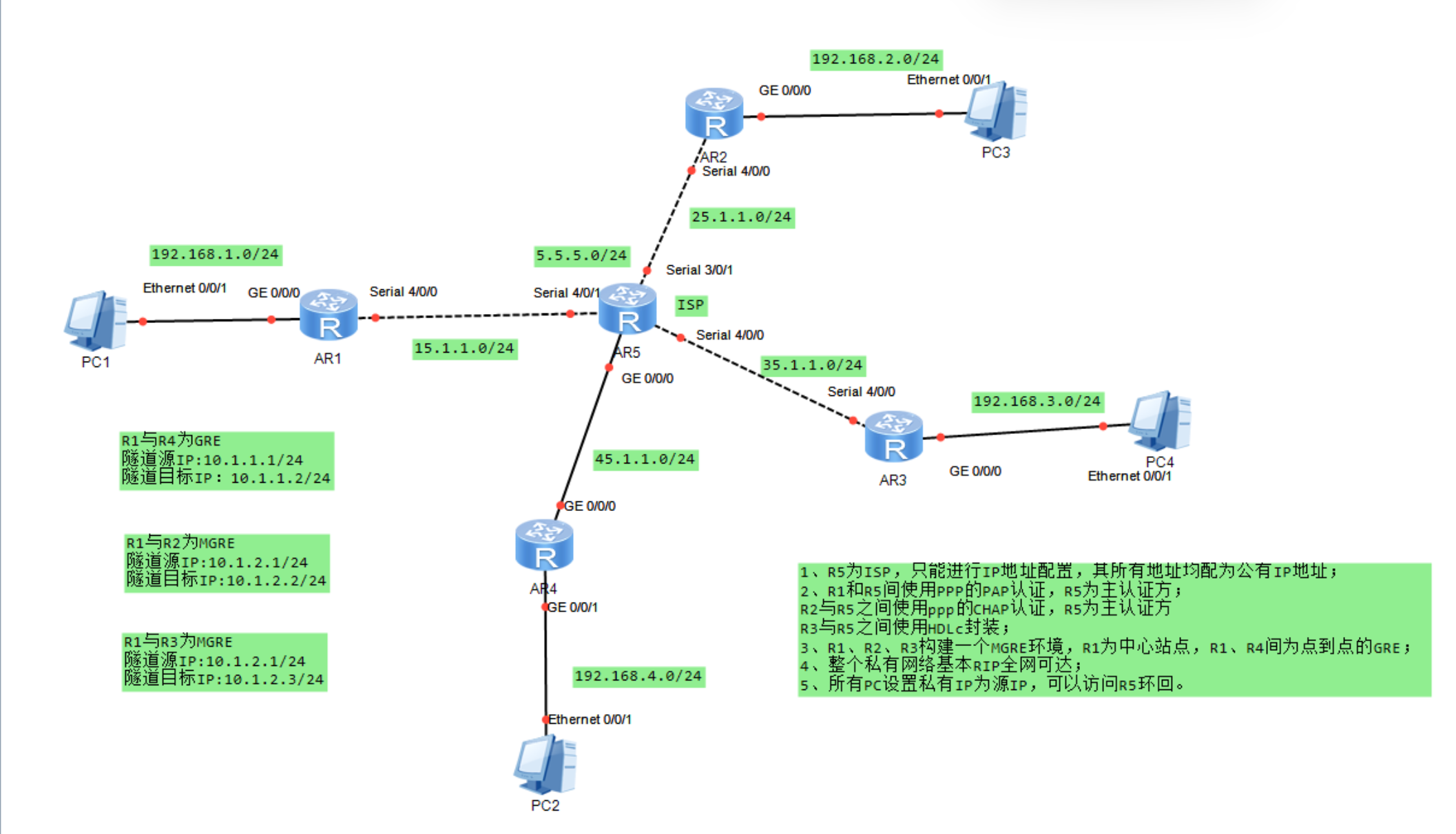
四、项目需求
1、R5为ISP,只能进行IP地址配置,其所有地址均配为公有IP地址;
2、R1和R5间使用PPP的PAP认证,R5为主认证方;
R2与R5之间使用ppp的CHAP认证,R5为主认证方
R3与R5之间使用HDLc封装;
3、R1、R2、R3构建一个MGRE环境,R1为中心站点,R1、R4间为点到点的GRE;
4、整个私有网络基本RIP全网可达;
5、所有PC设置私有IP为源IP,可以访问R5环回。
五、项目思路
1、依据划分的网段,为所有 PC 及路由器接口配置 IP 地址;
2、为 R1 与 R5 配置 PPP 的 PAP 认证,以 R5 作为主认证方;
3、为 R2 与 R5 配置 PPP 的 CHAP 认证,以 R5 作为主认证方;
4、配置 R3 与 R5 之间采用 HDLC 封装;
5、在 R1 至 R5 上配置默认路由,实现公网互通;
6、在 R1 与 R4 之间建立点对点的 GRE 隧道;
7、将 R1、R2、R3 搭建为 MGRE 环境,以 R1 作为中心站点;
8、配置 RIP 协议以传递私网路由。
六、项目步骤
6.1 为所有PC机以及路由器接口配置IP地址
(1)PC机
自行手动添加
(2)路由器接口
R1:
R1int g0/0/0
R1-GigabitEthernet0/0/0ip add 192.168.1.254 24
R1-GigabitEthernet0/0/0int s4/0/0
R1-Serial4/0/0ip add 15.1.1.1 24
R2:R2int g0/0/0
R2-GigabitEthernet0/0/0ip add 192.168.2.254 24
R2-GigabitEthernet0/0/0int s4/0/0
R2-Serial4/0/0ip add 25.1.1.1 24
R3:R3int g0/0/0
R3-GigabitEthernet0/0/0ip add 192.168.3.254 24
R3-GigabitEthernet0/0/0int s4/0/0
R3-Serial4/0/0ip add 35.1.1.1 24
R4:R4int g0/0/1
R4-GigabitEthernet0/0/1ip add 192.168.4.254 24
R4-GigabitEthernet0/0/1int g0/0/0
R4-GigabitEthernet0/0/0ip add 45.1.1.1 24
R5:R5int g0/0/0
R5-GigabitEthernet0/0/0ip add 45.1.1.2 24
R5-GigabitEthernet0/0/0int s4/0/1
R5-Serial4/0/1ip add 15.1.1.2 24
R5-Serial4/0/1int s3/0/1
R5-Serial3/0/1ip add 25.1.1.2 24
R5-Serial3/0/1int s4/0/0
R5-Serial4/0/0ip add 35.1.1.2 24
R5环回口:R5int l0
R5-LoopBack0ip add 5.5.5.1 24
6.2 R1和R5间使用PPP的PAP认证,R5为主认证方
R5:
R5aaa
R5-aaalocal-user wangdaye password cipher 123321
Info: Add a new user.
R5-aaalocal-user wangdaye service-type ppp
R5int s4/0/1
R5-Serial4/0/1ppp authentication-mode PAP
R5-Serial4/0/1link-protocol ppp
R1:R1int s4/0/0
R1-Serial4/0/0ppp pap local-user wangdaye password cipher 123321
6.3 R2与R5之间使用ppp的CHAP认证,R5为主认证方
R2:
R2int s4/0/0
R2-Serial4/0/0ppp pap local-user 123 password cipher 123321
6.4 配置R3与R5之间使用HDLC封装
R3:
R3int s4/0/0
R3-Serial4/0/0link-protocol HDLC
R5:R5int s4/0/0
R5-Serial4/0/0link-protocol HDLC
6.5 在R1~R5上配置默认路由使公网互通
R1:
R1ip route-static 0.0.0.0 0 15.1.1.2
R2:
R2ip route-static 0.0.0.0 0 25.1.1.2
R3:
R3ip route-static 0.0.0.0 0 35.1.1.2
R5:
R4ip route-static 0.0.0.0 0 45.1.1.2
6.6 建立R1、R4间点到点的GRE
(1)在R1上创建Tunnel口,模式为GRE,源地址和目的地址为本端公网地址和对端公网地址
R1int tunnel0/0/0
R1-Tunnel0/0/0tunnel-protocol gre
R1-Tunnel0/0/0ip add 10.1.1.1 24
R1-Tunnel0/0/0source 15.1.1.1
R1-Tunnel0/0/0destination 45.1.1.1
(2)在R4上创建Tunnel口,模式为GRE,源地址和目的地址为本端公网地址和对端公网地址R4int tunnel0/0/0
R4-Tunnel0/0/0tunnel-protocol gre
R4-Tunnel0/0/0ip add 10.1.1.2 24
R4-Tunnel0/0/0source 45.1.1.1
R4-Tunnel0/0/0destination 15.1.1.1
6.7 将R1、R2、R3构建一个MGRE环境,R1为中心站点
(1)配置总部与分部之间的隧道-MGRE VPN
R1:
R1int tunnel0/0/1
R1-Tunnel0/0/1tunnel-protocol gre p2mp
R1-Tunnel0/0/1ip add 10.1.2.1 24
R1-Tunnel0/0/1source 15.1.1.1
R2:R2int tunnel0/0/1
R2-Tunnel0/0/1tunnel-protocol gre p2mp
R2-Tunnel0/0/1ip add 10.1.2.2 24
R2-Tunnel0/0/1source 25.1.1.1
R3:R3int tunnel0/0/1
R3-Tunnel0/0/1tunnel-protocol gre p2mp
R3-Tunnel0/0/1ip add 10.1.2.3 24
R3-Tunnel0/0/1source 35.1.1.1
(2)NHRP的配置
中心站点配置:
R1:
R1int tunnel0/0/1
R1-Tunnel0/0/1nhrp network-id 100
分支站点配置:
R2:
R2int tunnel 0/0/1
R2-Tunnel0/0/1nhrp network-id 100
R2-Tunnel0/0/1nhrp entry 10.1.2.1 15.1.1.1 register
R3:
R3int tunnel0/0/1
R3-Tunnel0/0/1nhrp network-id 100
R3-Tunnel0/0/1nhrp entry 10.1.2.1 15.1.1.1
6.8 配置rip来传递私网路由
R1:
R1rip 1
R1-rip-1undo summary
R1-rip-1version 2
R1-rip-1network 192.168.1.0
R1-rip-1network 10.0.0.0
R2:
R2rip 1
R2-rip-1undo summary
R2-rip-1version 2
R2-rip-1network 192.168.2.0
R2-rip-1network 10.0.0.0
R3:
R3rip 1
R3-rip-1undo summary
R3-rip-1version 2
R3-rip-1network 192.168.4.0
R3-rip-1network 10.0.0.0
R4:
R4rip 1
R4-rip-1undo summary
R4-rip-1version 2
R4-rip-1network 192.168.4.0
R4-rip-1network 10.0.0.0
在 中心上开启伪广播:R1int tunnel0/0/1
R1-Tunnel0/0/1nhrp entry multicast dynamic
关闭RIP的水平分割机制:R1-Tunnel0/0/1undo rip split-horizon
R2-Tunnel0/0/1undo rip split-horizon
R3-Tunnel0/0/1undo rip split-horizon
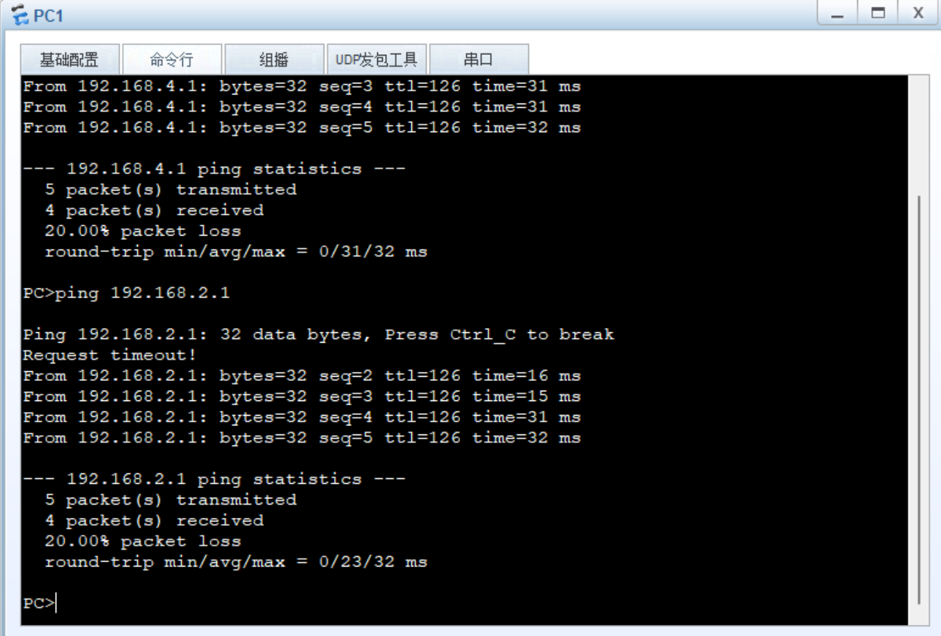
七、项目结果
八、项目总结
本实验成功构建了 GRE 及 MGRE 综合网络:R5 作为 ISP 配置公网 IP,R1 与 R5 通过 PAP 认证、R2 与 R5 通过 CHAP 认证,R3 与 R5 采用 HDLC 封装,实现链路层安全与兼容;R1-R3 搭建 MGRE 星型环境,R1 与 R4 建立点对点 GRE 隧道,结合 RIP 协议实现私有网络全网可达;所有 PC 以私有 IP 为源,通过隧道成功访问 R5 环回。实验验证了 GRE/MGRE 隧道的跨网互联能力、PPP 认证的安全性及路由协议的有效性,为复杂网络中 VPN 技术的整合应用提供了实践参考。