需求分析:
1、配置设备组建M-LAG系统,配置服务器M-LAG双归接入IP网络。
2、配置Monitor Link关联上行接口和下行接口,避免因上行链路故障导致流量丢弃,使用命令timer recover-time配置回切时间,防止上行链路故障回切后因为路由没有收敛而导致丢包。
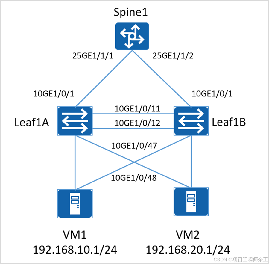
3、Leaf1A与Leaf1B之间组建M-LAG系统,Peer-Link接口为Eth-Trunk0,成员接口为各设备上的10 GE1/0/11与10GE1/0/12接口。
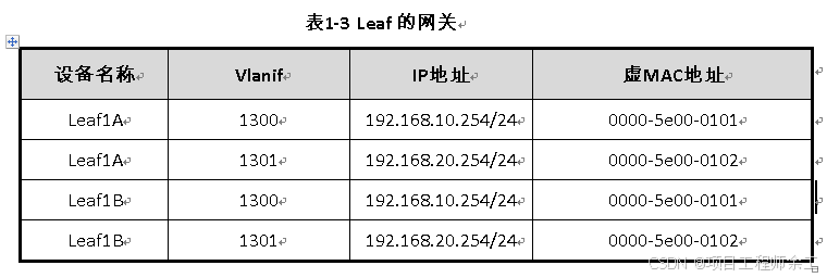
4、Leaf设备的网关规划连接VM1的物理口允许Vlan1300通过,连接VM2的物理口允许Vlan1301通过。
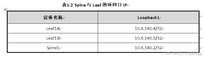
5、Spine1与Leaf1A、Leaf1B之间运行OSPF协议,所有接口均属于OSPF区域0(包括Loopback1接口),Spine1上Loopback1接口IP地址模拟服务器需要访问的外部地址。
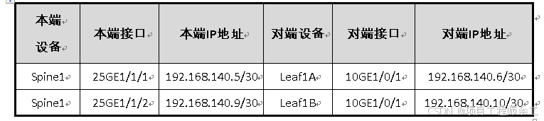
表1-1 设备互联接口IP
Leaf1A配置
Leaf1A interface LoopBack1
Leaf1A-LoopBack0 ip address 10.6.140.4 32
Leaf1A-LoopBack0 quit
Leaf1A interface 10GE1/0/1
Leaf1A-10GE1/0/1 undo portswitch
Leaf1A-10GE1/0/1 ip address 192.168.140.6 30
Leaf1A-10GE1/0/1 quit
m-lag配置
Leaf1A stp mode rstp
Leaf1A stp v-stp enable
Leaf1A dfs-group 1
Leaf1A-dfs-group-1 source ip 10.6.140.4 //这条命令可能不支持就用这个dual-active detection source ip XX peer XX
Leaf1A-dfs-group-1 priority 150
Leaf1A-dfs-group-1 quit
Leaf1A interface eth-trunk 0
Leaf1A-Eth-Trunk0 trunkport 10ge 1/0/11
Leaf1A-Eth-Trunk0 trunkport 10ge 1/0/12
Leaf1A-Eth-Trunk0 mode lacp-static
Leaf1A-Eth-Trunk0 peer-link 1
Leaf1A-Eth-Trunk0 quit
在Leaf1A上配置连接VM1接口的M-LAG工作组
Leaf1A interface eth-trunk 1
Leaf1A -Eth-Trunk1 trunkport 10GE 1/0/47
Leaf1A -Eth-Trunk1 port link-type trunk
Leaf1A -Eth-Trunk1 undo port trunk allow-pass vlan 1
Leaf1A -Eth-Trunk1 mode lacp-static
Leaf1A -Eth-Trunk1 dfs-group 1 m-lag 1
Leaf1A -Eth-Trunk1 quit
Leaf1A interface eth-trunk 2
Leaf1A -Eth-Trunk2 trunkport 10GE 1/0/48
Leaf1A -Eth-Trunk2 port link-type trunk
Leaf1A -Eth-Trunk2 undo port trunk allow-pass vlan 1
Leaf1A -Eth-Trunk2 mode lacp-static
Leaf1A -Eth-Trunk2 dfs-group 1 m-lag 2
Leaf1A -Eth-Trunk2 quit
步骤 3 配置网关和OSPF协议
配置M-LAG工作组的允许通过的vlan和创建vlanif
在Leaf1A上配置连接VM1接口的M-LAG工作组允许通过的vlan和创建vlanif
Leaf1Avlan 1300
Leaf1A-vlan1300quit
Leaf1Ainterface Eth-Trunk1
Leaf1A-Eth-Trunk1port trunk allow-pass vlan 1300
Leaf1A-Eth-Trunk1 quit
Leaf1Ainterface Vlanif 1300
Leaf1A-Vlanif1300 ip address 192.168.10.254 24
Leaf1A-Vlanif1300mac-address 0000-5e00-0101
在Leaf1A上配置连接VM2接口的M-LAG工作组允许通过的vlan和创建vlanif
Leaf1Avlan 1301
Leaf1A-vlan1301quit
Leaf1Ainterface Eth-Trunk2
Leaf1A-Eth-Trunk2port trunk allow-pass vlan 1301
Leaf1A-Eth-Trunk2 quit
Leaf1Ainterface Vlanif 1301
Leaf1A-Vlanif1301 ip address 192.168.20.254 24
Leaf1A-Vlanif1301mac-address 0000-5e00-0102
在Leaf1A上配置OSPF,将互联接口、Loopback1接口、Vlanif接口宣告进OSPF中。
Leaf1Aospf 1 router-id 10.6.140.4
Leaf1A-ospf-1 area 0
Leaf1A-ospf-1-area-0.0.0.0 network 10.6.140.4 0.0.0.0
Leaf1A-ospf-1-area-0.0.0.0 network 192.168.140.4 0.0.0.3
Leaf1A-ospf-1-area-0.0.0.0 network 192.168.10.0 0.0.0.255
Leaf1A-ospf-1-area-0.0.0.0 network 192.168.20.0 0.0.0.255
Leaf1A-ospf-1-area-0.0.0.0 quit
Leaf1A-ospf-1 quit
Leaf增加Monitor-link配置,下行接口需要添加所有业务接口。
Leaf1A配置如下:
Leaf1A monitor-link group 1
Leaf1A-mtlk-group1 port 10GE1/0/1 uplink
Leaf1A-mtlk-group1 port 10GE1/0/47 downlink 1
Leaf1A-mtlk-group1 port 10GE1/0/48 downlink 2
Leaf1A-mtlk-group1 timer recover-time 60
Leaf1A-mtlk-group1 quit
Leaf1B配置
Leaf1B interface LoopBack1
Leaf1B-LoopBack1 ip address 10.6.140.5 32
Leaf1B-LoopBack1 quit
Leaf1B interface 10GE1/0/1
Leaf1B-10GE1/0/1 undo portswitch
Leaf1B-10GE1/0/1 ip address 192.168.140.10 30
Leaf1B-10GE1/0/1 quit
m-lag配置
Leaf1B stp mode rstp
Leaf1B stp v-stp enable
Leaf1B dfs-group 1
Leaf1B-dfs-group-1 source ip 10.6.140.5 //这条命令可能不支持就用这个dual-active detection source ip XX peer XX
Leaf1B-dfs-group-1 priority 120
Leaf1B-dfs-group-1 quit
Leaf1B interface eth-trunk 0
Leaf1B-Eth-Trunk0 trunkport 10ge 1/0/11
Leaf1B-Eth-Trunk0 trunkport 10ge 1/0/12
Leaf1B-Eth-Trunk0 mode lacp-static
Leaf1B-Eth-Trunk0 peer-link 1
Leaf1B-Eth-Trunk0 quit
在Leaf1B上配置连接VM1接口的M-LAG工作组
Leaf1B interface eth-trunk 1
Leaf1B -Eth-Trunk1 trunkport 10GE 1/0/47
Leaf1B -Eth-Trunk1 port link-type trunk
Leaf1B -Eth-Trunk1 undo port trunk allow-pass vlan 1
Leaf1B -Eth-Trunk1 mode lacp-static
Leaf1B -Eth-Trunk1 dfs-group 1 m-lag 1
Leaf1B -Eth-Trunk1 quit
Leaf1B interface eth-trunk 2
Leaf1B -Eth-Trunk2 trunkport 10GE 1/0/48
Leaf1B -Eth-Trunk2 port link-type trunk
Leaf1B -Eth-Trunk2 undo port trunk allow-pass vlan 1
Leaf1B -Eth-Trunk2 mode lacp-static
Leaf1B -Eth-Trunk2 dfs-group 1 m-lag 2
Leaf1B -Eth-Trunk2 quit
在Leaf1B上配置连接VM1接口的M-LAG工作组允许通过的vlan和创建vlanif
Leaf1Bvlan 1300
Leaf1B-vlan1300quit
Leaf1Binterface Eth-Trunk1
Leaf1B-Eth-Trunk1port trunk allow-pass vlan 1300
Leaf1B-Eth-Trunk1 quit
Leaf1Binterface Vlanif 1300
Leaf1B-Vlanif1300 ip address 192.168.10.254 24
Leaf1B-Vlanif1300mac-address 0000-5e00-0101
在Leaf1B上配置连接VM2接口的M-LAG工作组允许通过的vlan和创建vlanif
Leaf1Bvlan 1301
Leaf1B-vlan1301quit
Leaf1Binterface Eth-Trunk2
Leaf1B-Eth-Trunk2port trunk allow-pass vlan 1301
Leaf1B-Eth-Trunk2 quit
Leaf1Binterface Vlanif 1301
Leaf1B-Vlanif1301 ip address 192.168.20.254 24
Leaf1B-Vlanif1301mac-address 0000-5e00-0102
在Leaf1B上配置OSPF,将互联接口、Loopback1接口、Vlanif接口宣告进OSPF中。
Leaf1Bospf 1 router-id 10.6.140.5
Leaf1B-ospf-1 area 0
Leaf1B-ospf-1-area-0.0.0.0 network 10.6.140.5 0.0.0.0
Leaf1B-ospf-1-area-0.0.0.0 network 192.168.140.8 0.0.0.3
Leaf1B-ospf-1-area-0.0.0.0 network 192.168.10.0 0.0.0.255
Leaf1B-ospf-1-area-0.0.0.0 network 192.168.20.0 0.0.0.255
Leaf1B-ospf-1-area-0.0.0.0 quit
Leaf1B-ospf-1 quit
Leaf1B Mointer-link配置如下:
Leaf1B monitor-link group 1
Leaf1B-mtlk-group1 port 10GE1/0/1 uplink
Leaf1B-mtlk-group1 port 10GE1/0/47 downlink 1
Leaf1B-mtlk-group1 port 10GE1/0/48 downlink 2
Leaf1B-mtlk-group1 timer recover-time 60
Leaf1B-mtlk-group1 quit
Spine1配置
Spine1 interface LoopBack1
Spine1-LoopBack1 ip address 10.6.140.2 32
Spine1-LoopBack1 quit
Spine1 interface 25GE1/1/1
Spine1-25GE1/1/1 port mode 10G
Spine1-25GE1/1/1 y
Spine1-25GE1/1/1 undo portswitch
Spine1-25GE1/1/1 ip address 192.168.140.5 30
Spine1-25GE1/1/1 quit
Spine1 interface 25GE1/1/2
Spine1-25GE1/1/2 undo portswitch
Spine1-25GE1/1/2 ip address 192.168.140.9 30
Spine1-25GE1/1/2 quit
在Spine1上配置OSPF,将互联接口、Loopback1接口宣告进OSPF中。
Spine1ospf 1 router-id 10.6.140.2
Spine1-ospf-1 area 0
Spine1-ospf-1-area-0.0.0.0 network 10.6.140.2 0.0.0.0
Spine1-ospf-1-area-0.0.0.0 network 192.168.140.4 0.0.0.3
Spine1-ospf-1-area-0.0.0.0 network 192.168.140.8 0.0.0.3
Spine1-ospf-1-area-0.0.0.0 quit
Spine1-ospf-1 quit