目录
[PCM 控制器](#PCM 控制器)
[PCM 模式支持](#PCM 模式支持)
[PCM 模式](#PCM 模式)
[PCM early](#PCM early)
[TDM Normal Mode (PCM Format)](#TDM Normal Mode (PCM Format))
需求很简单: 3588增加PCM 接口。客户对此接口也不了解。无其他说明。
硬件能力
控制器数目
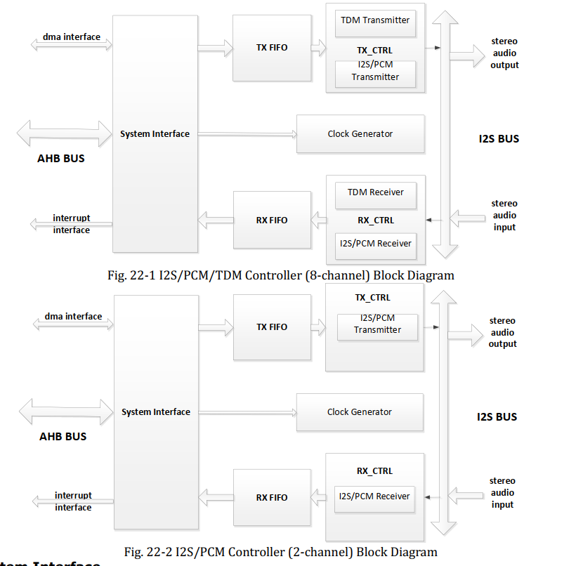
There are nine I2S/PCM/TDM controllers and two I2S/PCM controllers embed in the system. I2S/PCM/TDM controllers support I2S format, PCM format and TDM format.
While I2S/PCM controllers only support I2S format and PCM format.
The nine I2S/PCM/TDM controllers are I2S0, I2S1, I2S4, I2S5, I2S6, I2S7, I2S8, I2S9 and I2S10. Remaining two I2S/PCM controllers are 2-channel I2S2 and I2S3。
主从模式
Support master and slave mode for I2S0, I2S1, I2S2 and I2S3
Support only master TX mode for I2S4, I2S5, I2S6 and I2S8
Support only slave RX mode for I2S7, I2S9 and I2S10
PCM 控制器
Support 2-channel audio transmitting and receiving in PCM mode for I2S0, I2S1, I2S2 and I2S3
Support 2-channel audio transmitting in PCM mode for I2S4, I2S5, I2S6 and I2S8
Support 2-channel audioreceivingin PCM mode for I2S7, I2S9 and I2S10
采样率支持
Support up to 192kHz sample rate for I2S0, I2S1, I2S2, I2S3, I2S4 and I2S8
Support up to 768kHz sample rate for I2S5, I2S6, I2S7, I2S9 and I2S10
384k 采样率需要高精度 clk,可从 MCLK PIN 导入外部高精度 clk 或者采用 slave 模式
PCM 模式支持
Support PCM early, late1, late2, late3 mode serial audio data transfer
帧大小支持
Support a range of 32 to 256 programmable frame width in I2S/PCM mode for I2S/PCM/TDM controllers and I2S/PCM controllers except I2S4 and I2S8
Support a range of 32 to 512 programmable frame width in I2S/PCM mode for I2S4 and I2S8
字节序
MSB or LSB first serial audio data transfe
能力总结
|---------|----------|--------|---|---|
| 控制器 | 通道数目 | 方向 | | |
| 0-3 | 2 | 收、发 | | |
| 4-6,8 | 2 | 发 | | |
| 7、9、10 | 2 | 收 | | |
I2S: 2 通道 or 8通道
PCM :2 通道
TDM: 16 通道
需求确认
1) 接收 or 发送 or双向。决定控制不同。
2) 采样率的上限要求。
3) 帧大小
PCM 模式
支持 stereo PCM 协议:early, late 1, late 2, late 3
不支持 mono PCM,如有需求,可采用 stereo PCM 传输 mono PCM,有效数据放在 slot 0
LRCK 高电平 为一个SCLK 周期(即一高一低)
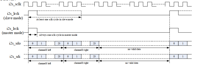
PCM early
This is the waveform of PCM early mode.
For LRCK (i2s_lrck) signal, it goes high to indicate the start of a group of audio channels. For SD (i2s_sdo, i2s_sdi) signal, it sends the first bit (MSB or LSB) at the same time when LRCK goes high. The range of SD signal width is from 16 to 32bits.
LRCK 变高时,SD开始输出第一位。
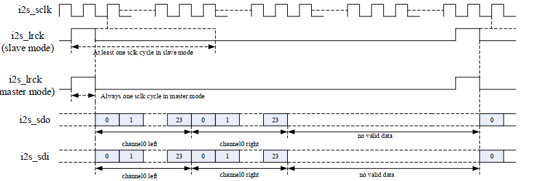
late1
This is the waveform of PCM early mode.
For LRCK (i2s_lrck) signal, it goes high to indicate the start of a group of audio channels.
For SD (i2s_sdo, i2s_sdi) signal, it sends the first bit (MSB or LSB) one SCLK clock cycle after LRCK goes high. The range of SD signal width is from 16 to 32bits.
LRCK 变高后的第一个SCLK时钟后,SD开始输出第一位。
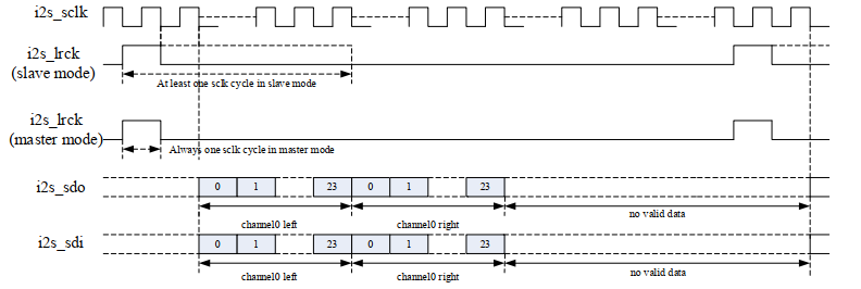
late2
This is the waveform of PCM early mode.
For LRCK (i2s_lrck) signal, it goes high to indicate the start of a group of audio channels.
For SD (i2s_sdo, i2s_sdi) signal, it sends the first bit(MSB or LSB) two SCLK clock cycles after LRCK goes high. The range of SD signal width is from 16 to 32bits.
LRCK 变高后的第二个SCLK时钟后,SD开始输出第一位。
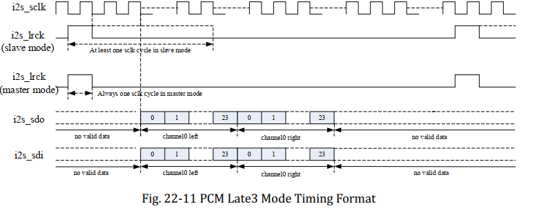
late3
This is the waveform of PCM early mode.
For LRCK (i2s_lrck) signal, it goes high to indicate the start of a group of audio channels.
For SD (i2s_sdo, i2s_sdi) signal, it sends the first bit (MSB or LSB) three SCLK clock cycles after LRCK goes high. The range of SD signal width is from 16 to 32bits
LRCK 变高后的第三个SCLK时钟后,SD开始输出第一位。
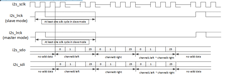
TDM Normal Mode (PCM Format)
This is the waveform of TDM normal mode.
For LRCK (i2s_lrck) signal, it goes high to indicate the start of a group of audio channels.
For SD (i2s_sdo, i2s_sdi) signal, it sends the first bit (MSB or LSB) on the second falling edge of SCLK after LRCK goes high. The range of SD signal width is from 16 to 32bits.
LRCK 变高后的第二个SCLK时钟下降沿,SD开始输出第一位。数据为左右各四个声道。
需求确认
1) pcm 模式
2) sd的数据位宽 ,支持16-32bit,需求是多少bit
codec芯片
I2S, Left Justified, DSP/PCM Mode
模式选择
ADC Control 4, Default 0000 0000
|-----------|-----|-------------------------------------------------------------------------------------------------------------------------------------------------------------------------|
| ADCFORMAT | 1:0 | 00 -- I2S serial audio data format 01 -- left justify serial audio data format 10 -- right justify serial audio data format 11 -- DSP/PCM mode serial audio data format |
PCM模式选择
|--------|---|--------------------------------------------------------------------------------------------------------------------------------------------------------------------------------------------------------------------------------------------------------------------------------------|
| ADCLRP | 5 | I2S, left justified or right justified mode: 0 -- left and right normal polarity 1 -- left and right inverted polarity DSP/PCM mode: 0 -- MSB is available on 2nd BCLK rising edge after ALRCK rising edge 1 -- MSB is available on 1st BCLK rising edge after ALRCK rising edge |
| | | |
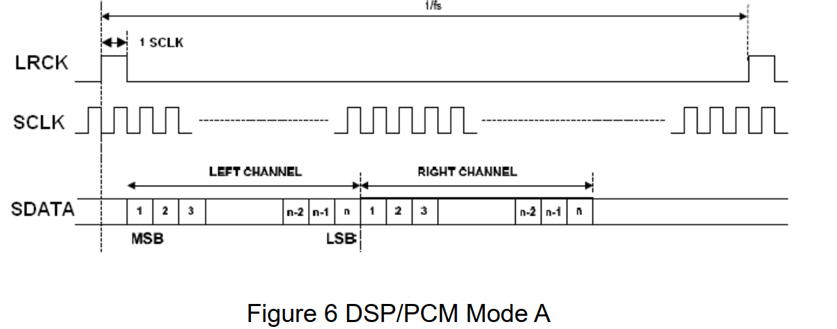
即3588 侧的late1 模式;
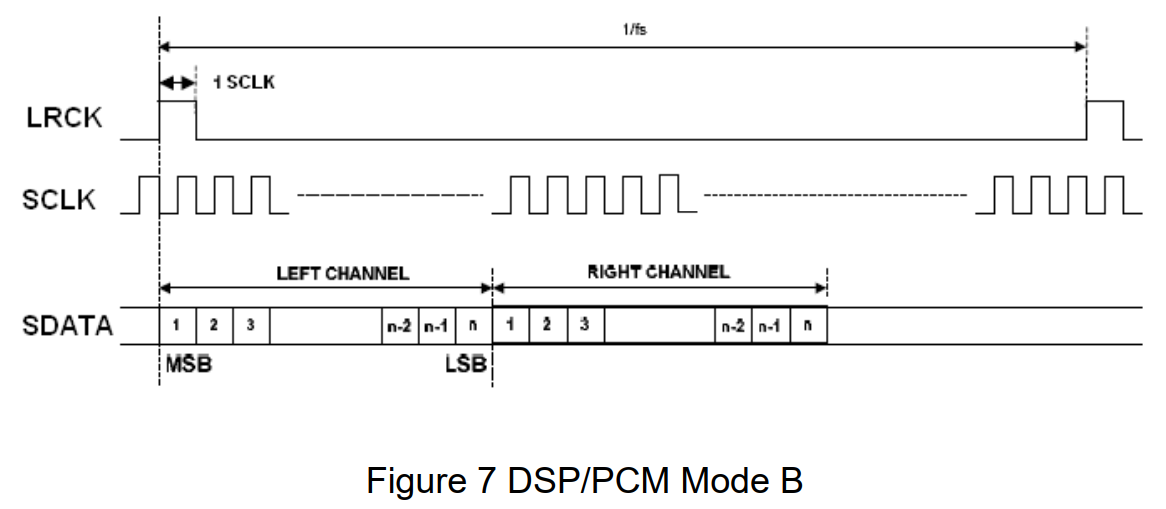
即 3588 侧的early模式
-
DSP A :帧同步脉冲后,延迟1个BCLK周期开始传输数据(类似于I2S的延迟思想)。
-
DSP B :帧同步脉冲后,立即(无延迟) 开始传输数据(类似于左对齐的思想)。
位宽
|--------------------------------------------|
| 24-bit, 8 kHz to 96 kHz sampling frequency |
|-------|-----|-----------------------------------------------------------------------------------------------------------------------------------------------------------------------------------------------------------------------------|
| ADCWL | 4:2 | 000 -- 24-bit serial audio data word length 001 -- 20-bit serial audio data word length 010 -- 18-bit serial audio data word length 011 -- 16-bit serial audio data word length 100 -- 32-bit serial audio data word length |
总结
总体而言 ,此接口相对简单。主要关注几点:
1) 硬件设计时的 控制器选择。哪些支持PCM,及他们的收发方向。
2) 做主、从的选择,通常我们默认SOC控制器做主,但客户实际应用是否有什么特殊要求,需要确认。
3)采样率。例如ES8388到96k,而且数据24bit情况下。 虽然3588的采样率可以更高,但对时钟有要求。而时钟则和单板设计相关。
4) PCM模式。模式不同,时序不同,这和软件配置相关。但支持情况由控制器限制。
5) 每个slot(即通道,例如左右声道)的数据位宽配置。
6) MSB LSB的配置。3588都支持,但具体配置如何需要确认。
7) 帧大小的要求。帧大小由通道数目,及每个通道的位数构成。例如2通道,每通道16bit,则帧大小为32,最小的帧。
前期我们单板上有如上两个器件,可以先行验证流程。具体细节再进一步客户沟通。