一、整体配置顺序(按课堂笔记规范)
- 基础配置:设备命名、VLAN 划分、Trunk/Access 接口配置
- 二层冗余:MSTP 双实例、Eth-Trunk 链路聚合
- 三层网关:三层交换机 VLANIF、VRRP 主备备份
- 地址服务:DHCP 全局配置与地址池
- 路由互通:OSPF 宣告、静态默认路由
- 出口上网:NAT 配置、回包路由
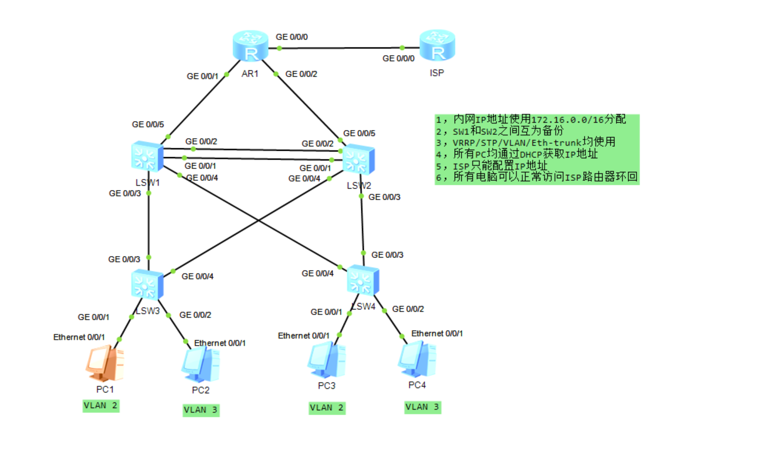
二、设备基础信息规划
| 设备 | 角色 | VLAN 规划 | 接口 IP/VRRP | 备注 |
|---|---|---|---|---|
| LSW1(汇聚 1) | 三层主设备 | VLAN2/3/101/102 | VLANIF2:172.16.2.254/24(VRRP 主)VLANIF3:172.16.3.252/24(VRRP 备)VLANIF101:172.16.101.1/24VLANIF102:172.16.102.1/24 | MSTP Instance1 主根、Instance2 备根 |
| LSW2(汇聚 2) | 三层备设备 | VLAN2/3/101/102 | VLANIF2:172.16.2.252/24(VRRP 备)VLANIF3:172.16.3.254/24(VRRP 主)VLANIF101:172.16.101.2/24VLANIF102:172.16.102.2/24 | MSTP Instance1 备根、Instance2 主根 |
| LSW3(接入 1) | 二层接入 | VLAN2/3 | 无 | 下联 PC1/2,上联 LSW1/LSW2 |
| LSW4(接入 2) | 二层接入 | VLAN2/3 | 无 | 下联 PC3/4,上联 LSW1/LSW2 |
| AR1(出口路由) | 内网网关 | 无 | GE0/0/0:10.12.1.1/24GE0/0/1:172.16.101.3/24GE0/0/2:172.16.102.4/24 | 连接 ISP,配置 NAT |
| ISP(运营商) | 外网模拟 | 无 | GE0/0/0:10.12.1.2/24(环回口模拟公网) | 仅配置 IP,无需额外服务 |
三、详细配置步骤(含解释)
1. 接入层交换机配置(LSW3/LSW4,二层设备)
关键原则:
- 下联 PC 用
access接口,严格划分 VLAN - 上联汇聚用
trunk接口,仅放行 VLAN2/3(最小透传原则) - 下联 PC 接口配置为
边缘接口,防止 STP 环路影响终端
LSW3 配置
1. 基础命名
sysname LSW3
2. 创建业务
VLAN vlan batch 2 3
3. 下联PC接口配置(Access模式)
interface Ethernet0/0/1# 接PC1,属于VLAN2
port link-type access
port default vlan 2
stp edged-port enable # 配置为边缘接口,关闭STP处理
interface Ethernet0/0/2 # 接PC2,属于VLAN3
port link-type access
port default vlan 3
stp edged-port enable
4. 上联汇聚交换机(Trunk模式)
stp mode mstp # 华为默认开启,显式配置保证规范
interface GigabitEthernet0/0/3# 上联LSW1
port link-type trunk
port trunk allow-pass vlan 2 3 # 仅放行业务VLAN,符合最小透传
interface GigabitEthernet0/0/4 # 上联LSW2
port link-type trunk
port trunk allow-pass vlan 2 3
5. MSTP配置(与汇聚层同步)
stp region-configuration
region-name MSTP # 域名称与汇聚一致
instance 1 vlan 2 # VLAN2映射到Instance1
instance 2 vlan 3 # VLAN3映射到Instance2
active # 激活MSTP域配置
LSW4 配置(与 LSW3 逻辑一致,仅下联接口 VLAN 对应)
sysname LSW4
vlan batch 2 3
下联PC接口
interface Ethernet0/0/1 # 接PC3,属于VLAN2
port link-type access
port default vlan 2
stp edged-port enable
interface Ethernet0/0/2 # 接PC4,属于VLAN3
port link-type access
port default vlan 3
stp edged-port enable # 上联汇聚接口
interface GigabitEthernet0/0/3 # 上联LSW1
port link-type trunk
port trunk allow-pass vlan 2 3
interface GigabitEthernet0/0/4 # 上联LSW2
port link-type trunk
port trunk allow-pass vlan 2 3
MSTP配置
stp mode mstp
stp region-configuration
region-name MSTP
instance 1 vlan 2
instance 2 vlan 3
active
2. 汇聚层交换机配置(LSW1/LSW2,三层核心)
关键原则:
- 先配置 VLAN/Trunk,再配置 MSTP 防环,最后配置三层功能
- MSTP 双实例实现 VLAN 流量负载分担
- Eth-Trunk 聚合上联链路,提升带宽 + 冗余
- VRRP 实现网关双机热备,虚拟 IP 为终端网关
LSW1 配置
1. 基础命名与VLAN创建
sysname LSW1
vlan batch 2 3 101 102 # 业务VLAN+互联VLAN
2. 下联接入层Trunk接口
interface GigabitEthernet0/0/3 # 接LSW3
port link-type trunk
port trunk allow-pass vlan 2 3
interface GigabitEthernet0/0/4 # 接LSW4
port link-type trunk
port trunk allow-pass vlan 2 3
3. 汇聚间Eth-Trunk链路聚合(LSW1-LSW2)
interface Eth-Trunk1
port link-type trunk
port trunk allow-pass vlan 2 3 101 102 # 放行所有VLAN
interface GigabitEthernet0/0/1
eth-trunk 1
interface GigabitEthernet0/0/2
eth-trunk 1
4. 上联出口路由的互联接口
interface GigabitEthernet0/0/5
port link-type access
port default vlan 101 # 划入VLAN101,配置三层IP
5. MSTP配置(主根+备根)
stp mode mstp
stp region-configuration
region-name MSTP
instance 1 vlan 2
instance 2 vlan 3
active
stp instance 1 root primary # Instance1主根,VLAN2流量走LSW1
stp instance 2 root secondary # Instance2备根,VLAN3流量走LSW2
6. 三层VLANIF配置(网关地址)
interface Vlanif2
ip address 172.16.2.254 255.255.255.0
interface Vlanif3
ip address 172.16.3.252 255.255.255.0
interface Vlanif101
ip address 172.16.101.1 255.255.255.0
interface Vlanif102
ip address 172.16.102.1 255.255.255.0
7. VRRP虚拟网关配置
interface Vlanif2
vrrp vrid 1 virtual-ip 172.16.2.253 # 虚拟网关IP,与LSW2一致
vrrp vrid 1 priority 120 # 优先级高于默认100,成为VLAN2主网关
interface Vlanif3
vrrp vrid 2 virtual-ip 172.16.3.253
vrrp vrid 2 priority 100 # 默认优先级,作为VLAN3备网关
8. DHCP全局配置(为PC分配IP)
dhcp enable
ip pool VLAN2 # VLAN2地址池
gateway-list 172.16.2.253 # 指向VRRP虚拟网关
network 172.16.2.0 mask 255.255.255.0
dns-list 114.114.114.114 lease day 7
ip pool VLAN3 # VLAN3地址池
gateway-list 172.16.3.253
network 172.16.3.0 mask 255.255.255.0
dns-list 114.114.114.114
interface Vlanif2
dhcp select global # 接口下调用全局地址池
interface Vlanif3
dhcp select global
9. OSPF路由配置(宣告内网网段)
ospf 1 router-id 1.1.1.1 # 手动指定Router-ID,保证稳定
area 0
network 172.16.2.0 0.0.0.255
network 172.16.3.0 0.0.0.255
network 172.16.101.0 0.0.0.255
network 172.16.102.0 0.0.0.255
LSW2 配置(与 LSW1 对称,调整主备角色)
sysname LSW2
vlan batch 2 3 101 102
下联接入层Trunk接口
interface GigabitEthernet0/0/3 # 接LSW3
port link-type trunk
port trunk allow-pass vlan 2 3
interface GigabitEthernet0/0/4 # 接LSW4
port link-type trunk
port trunk allow-pass vlan 2 3
汇聚间Eth-Trunk(与LSW1对应)
interface Eth-Trunk1
port link-type trunk
port trunk allow-pass vlan 2 3 101 102
interface GigabitEthernet0/0/1
eth-trunk 1
interface GigabitEthernet0/0/2
eth-trunk 1
上联出口路由的互联接口
interface GigabitEthernet0/0/5
port link-type access
port default vlan 102
MSTP配置(备根+主根,实现负载分担)
stp mode mstp
stp region-configuration
region-name MSTP
instance 1 vlan 2
instance 2 vlan 3
active
stp instance 1 root secondary # Instance1备根
stp instance 2 root primary # Instance2主根,VLAN3流量走LSW2
三层VLANIF配置
interface Vlanif2
ip address 172.16.2.252 255.255.255.0
interface Vlanif3
ip address 172.16.3.254 255.255.255.0
interface Vlanif101
ip address 172.16.101.2 255.255.255.0
interface Vlanif102
ip address 172.16.102.2 255.255.255.0
VRRP配置(与LSW1相反)
interface Vlanif2
vrrp vrid 1 virtual-ip 172.16.2.253
vrrp vrid 1 priority 100
interface Vlanif3
vrrp vrid 2 virtual-ip 172.16.3.253
vrrp vrid 2 priority 120 # 成为VLAN3主网关
DHCP配置(与LSW1保持一致,主备冗余)
dhcp enable
ip pool VLAN2
gateway-list 172.16.2.253
network 172.16.2.0 mask 255.255.255.0
dns-list 114.114.114.114
ip pool VLAN3
gateway-list 172.16.3.253
network 172.16.3.0 mask 255.255.255.0
dns-list 114.114.114.114
interface Vlanif2
dhcp select global
interface Vlanif3
dhcp select global
OSPF配置
ospf 1 router-id 2.2.2.2
area 0
network 172.16.2.0 0.0.0.255
network 172.16.3.0 0.0.0.255
network 172.16.101.0 0.0.0.255
network 172.16.102.0 0.0.0.255
3. 出口路由器 AR1 配置(三层路由 + NAT 上网)
1. 基础配置
sysname AR1
interface GigabitEthernet0/0/0 # 连接ISP的外网接口
ip address 10.12.1.1 255.255.255.0
interface GigabitEthernet0/0/1 # 连接LSW1的VLAN101
ip address 172.16.101.3 255.255.255.0
interface GigabitEthernet0/0/2 # 连接LSW2的VLAN102
ip address 172.16.102.4 255.255.255.0
2. OSPF配置(与汇聚层同步,宣告内网网段)
ospf 1 router-id 3.3.3.3
area 0
network 172.16.101.0 0.0.0.255
network 172.16.102.0 0.0.0.255
3. 配置默认路由(指向ISP,实现外网访问)
ip route-static 0.0.0.0 0.0.0.0 10.12.1.2
4. NAT配置(PAT转换,实现多PC共享公网IP)
acl number 2000
定义允许转换的内网网段
rule permit source 172.16.2.0 0.0.0.255
rule permit source 172.16.3.0 0.0.0.255
interface GigabitEthernet0/0/0
nat outbound 2000 # 在外网接口应用NAT
4. ISP 路由器配置(仅基础 IP,模拟公网)
sysname ISP
interface GigabitEthernet0/0/0
ip address 10.12.1.2 255.255.255.0
interface LoopBack0 # 模拟公网环回口,验证访问
ip address 8.8.8.8 255.255.255.255
回包路由配置(关键!否则无法访问内网)
ip route-static 172.16.0.0 255.255.0.0 10.12.1.1
四、关键配置解释
-
MSTP 双实例防环 MSTP 是二层备份的最佳选择,这里通过两个实例让 VLAN2 和 VLAN3 分别以不同汇聚交换机为根桥,既解决了环路问题,又实现了流量负载分担,避免单链路拥塞。
-
VRRP 主备网关 通过
priority参数实现主备切换:LSW1 是 VLAN2 主网关,LSW2 是 VLAN3 主网关,故障时优先级高的设备自动抢占,保证终端网关始终可用。 -
最小透传原则所有 Trunk 接口仅放行必要的 VLAN,如接入层上联口只放 VLAN2/3,避免广播风暴扩散
-
二层→三层配置顺序完成 VLAN/STP/Trunk 等二层配置,再配置三层 IP/VRRP/OSPF,防止未处理生成树导致环路,先防环再路由。
-
DHCP 与三层交换机结合 DHCP 应在路由器 / 三层交换机完成,这里直接在汇聚三层交换机上配置全局地址池,无需额外部署 DHCP 服务器,同时通过 VRRP 虚拟网关保证地址池的冗余性。
五、验证与测试步骤
- 终端 PC 验证:PC1/3 获取 VLAN2 的 IP,PC2/4 获取 VLAN3 的 IP,能 ping 通 VRRP 虚拟网关。
- 二层冗余验证:断开 LSW1 的上联链路,PC 流量自动切换到 LSW2,无中断。
- 三层路由验证:在 AR1 上查看 OSPF 邻居,确认汇聚层网段都已学习。
- 外网访问验证:PC ping ISP 的环回口 8.8.8.8,能正常通说明 NAT 和路由配置正确。