一、DWC IP 使用
1.1 device
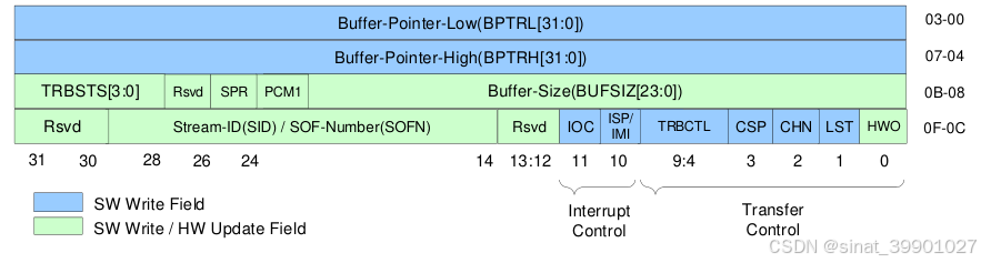
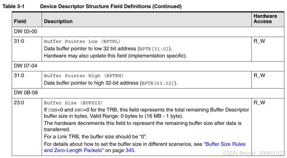
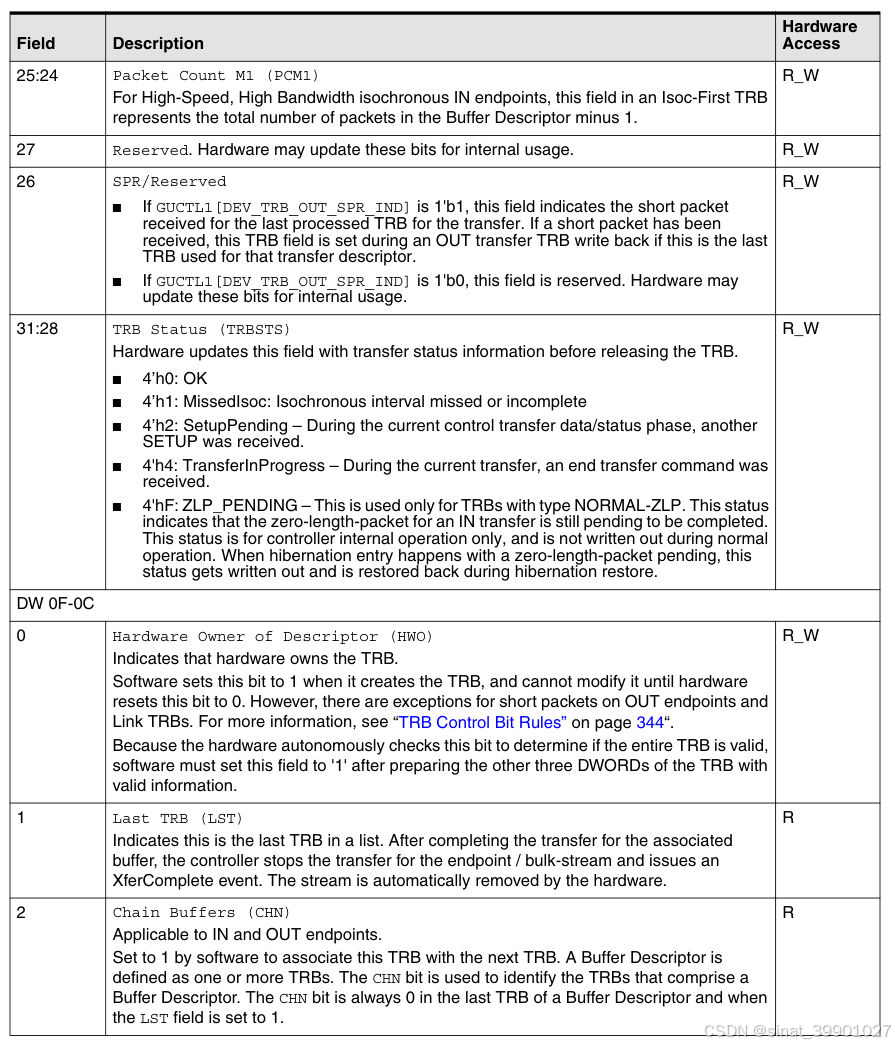
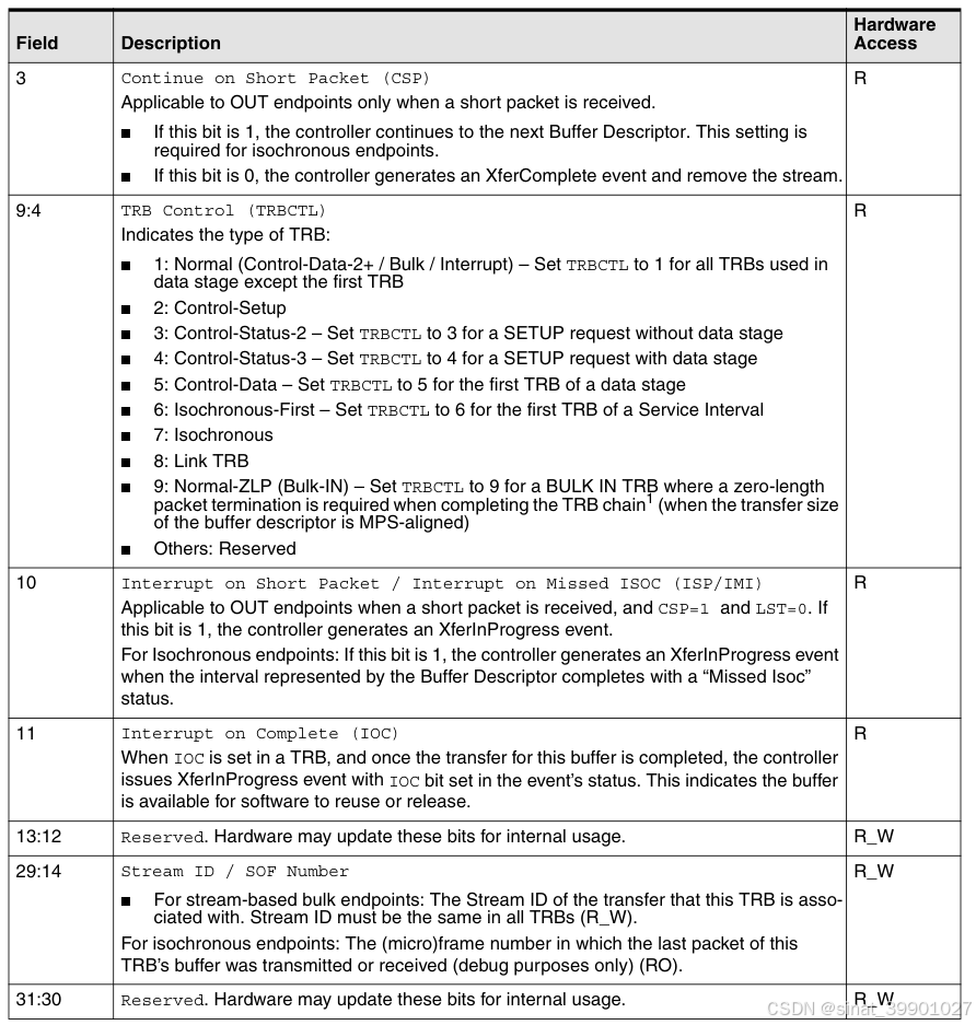
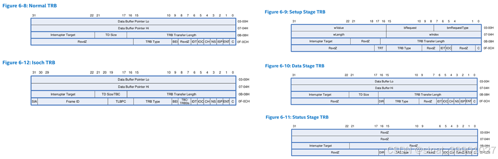
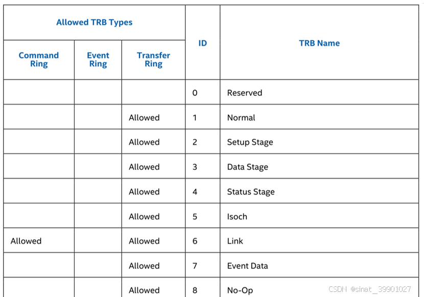
1.1.1 TRB
Buffer Size Rules and Zero-Length Packets
The hardware contains a cache that holds a fixed number of TRBs per transfer, configured through the coreConsultant parameter DWC_USB3_CACHE_TRBS_PER_TRANSFER or 15, whichever is smaller.
For IN endpoints, the following rules apply:
■ The number of chained TRBs necessary to construct a single packet must never exceed (DWC_USB3_CACHE_TRBS_PER_TRANSFER -- 1). A maximum of one Link TRB can be present in the chain.
■ If software wants to indicate a transfer completion to the host by sending a zero-length packet after a multiple of MaxPacketSize, it must set up a zero-length TRB following the last TRB in the transfer.
For OUT endpoints, the following rules apply:
■ The BUFSIZ field must be ≥ 1 byte.
■ The total size of a Buffer Descriptor must be a multiple of MaxPacketSize .
■ For setup stage of control transfer, BUFSIZ field must be 8 bytes.
■ A received zero-length packet still requires a MaxPacketSize buffer. Therefore, if the expected amount of data to be received is a multiple of MaxPacketSize, software should add MaxPacketSize bytes to the buffer to sink a possible zero-length packet at the end of the transfer.
For IN and OUT endpoints, the following rule applies:
■ The BUFSIZ field in a Link TRB must be set to 0
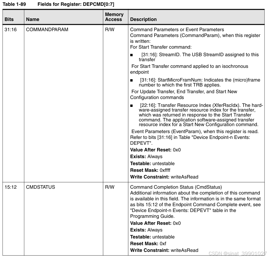
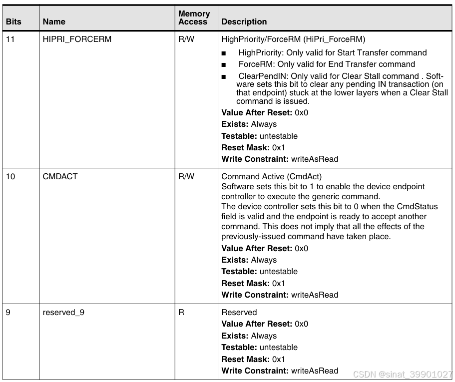
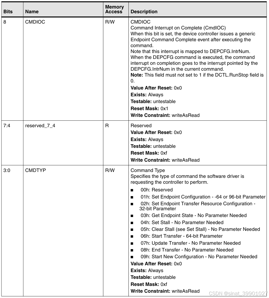
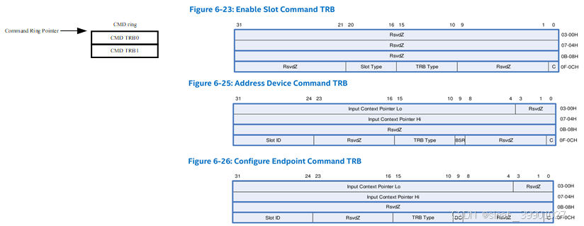
1.1.2 DEV CMD
寄存器
DEPCMDPAR2 0xc800 + ep_num X 0x10
DEPCMDPAR1 0xc804 + ep_num X 0x10
DEPCMDPAR0 0xc808 + eo_num X 0x10
DEPCMD 0xc80c + eo_num X 0x10
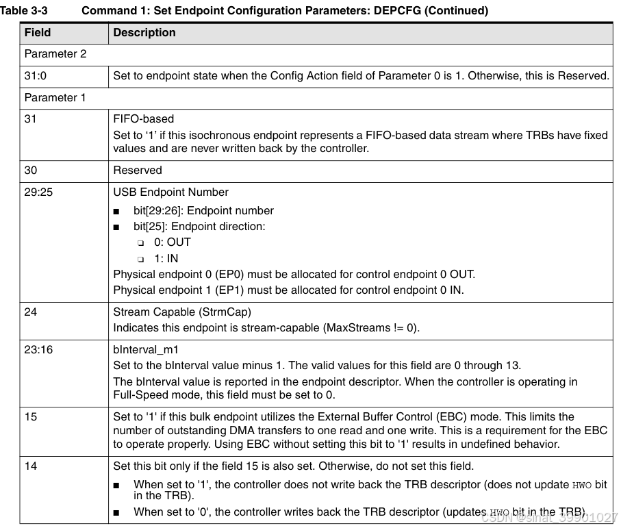
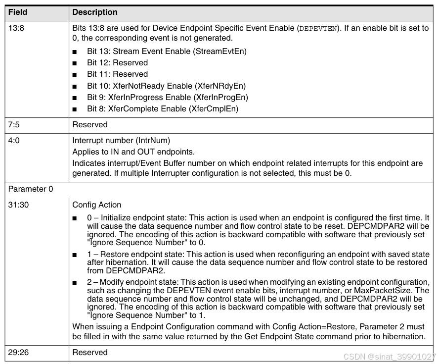
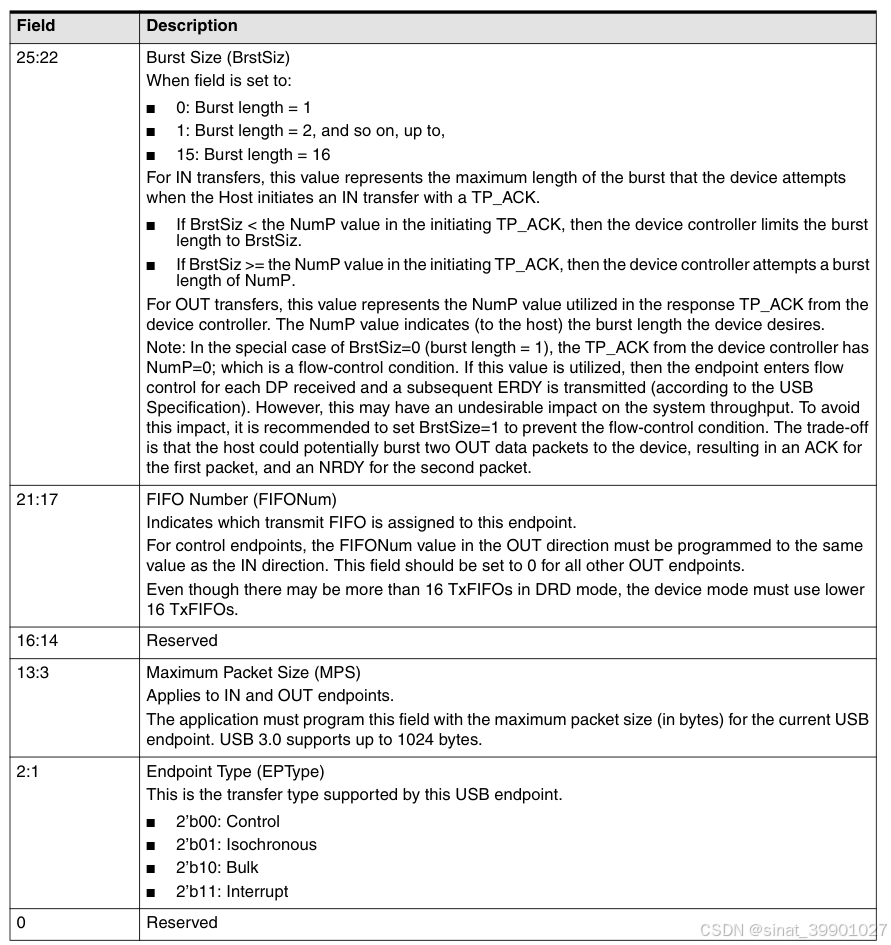
Command 1: Set Endpoint Configuration: DEPCFG
不同 out ep 需要指定不同的 FIFO
Command 2: Set Endpoint Transfer Resource Configuration (DEPXFERCFG)
Command 3: Get Endpoint State (DEPGETSTATE)
Commands 4 and 5: Set Stall and Clear Stall (DEPSSTALL, DEPCSTALL)
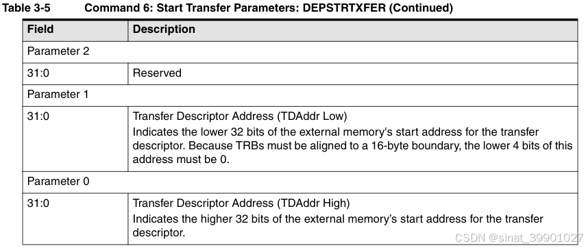
Command 6: Start Transfer (DEPSTRTXFER)
Command 7: Update Transfer (DEPUPDXFER)
If software uses circular TRB buffers and updates a TRB, whose Hardware Owner (HWO) bit was 0, by setting HWO=1, it must execute the Update Transfer command, specifying the transfer resource index of the TRB in the DEPCMD register. The hardware uses this information to re-cache the TRB.
Software may issue a special "No Response Update Transfer" command by setting CmdAct=0 and CmdIOC=0. In this case, the hardware does not generate a Command Complete event, does not set the CmdAct bit to '0' (because it will be '0'), and software may immediately issue another command to the same endpoint following this one. This special type of Update Transfer may not be used when software depends on the XferNotReady event to setup TRBs.
Software may issue an Update Transfer command for a transfer resource that has already completed (either due to XferComplete event or an End Transfer command), and the controller will detect that the Update Transfer is unnecessary. However, software must not issue an Update Transfer command for a transfer resource index that has never been started.
Command 8: End Transfer (DEPENDXFER)
Command 9: Start New Configuration (DEPSTARTCFG)
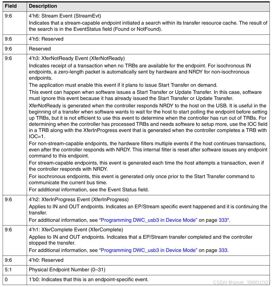
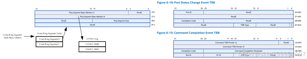
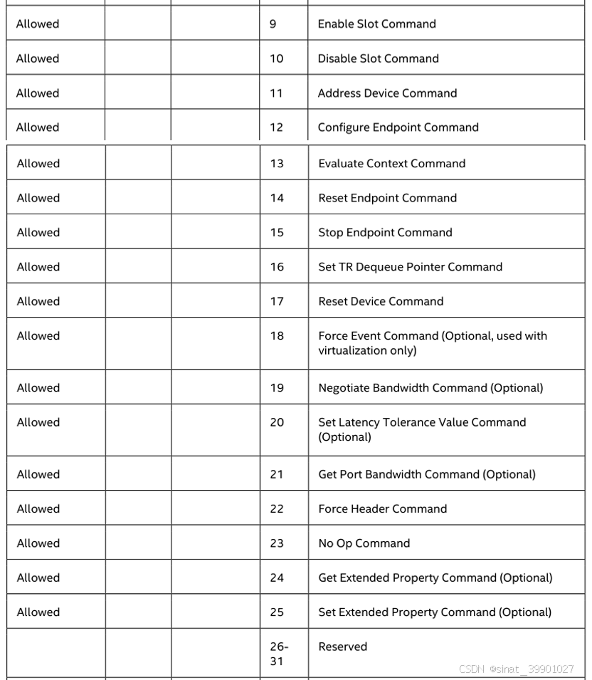
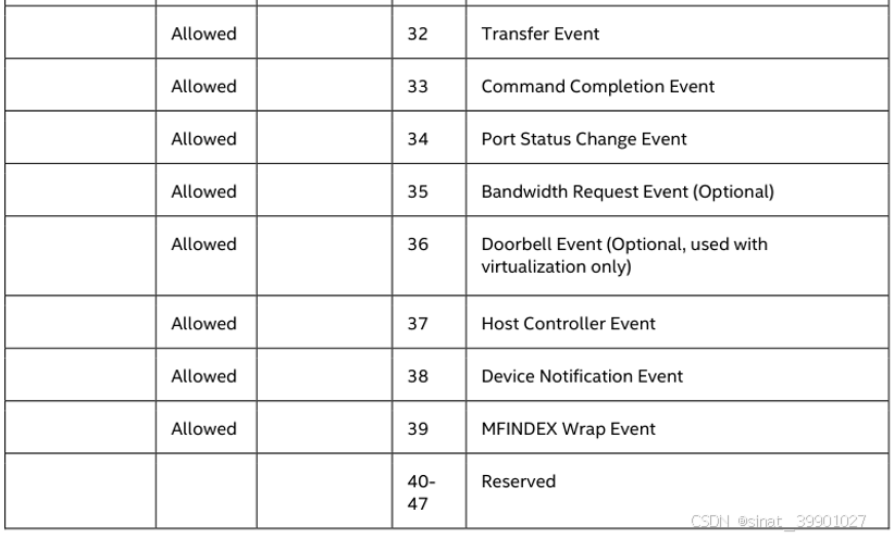
1.1.3 event
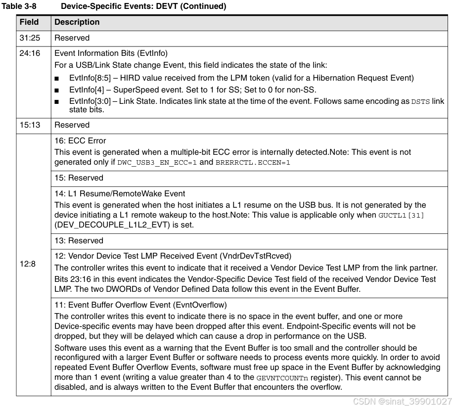
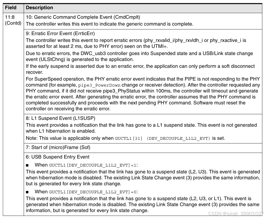
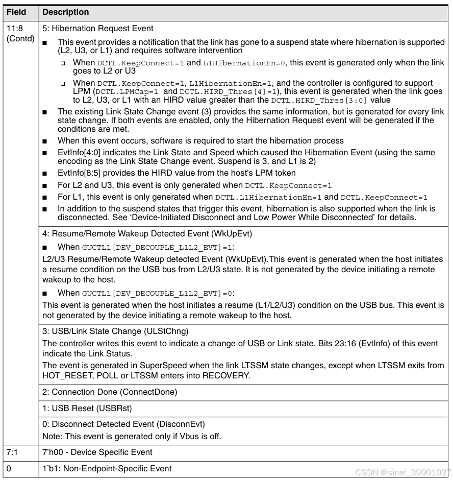
dev event
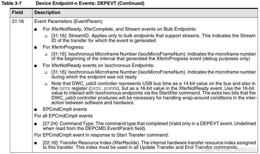
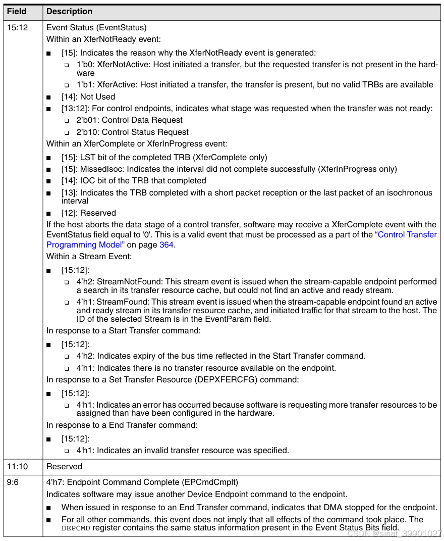
ep event
1.1.4 初始化配置流程
Power-On or Soft Reset Register Initialization
- Set the DCTL CSftRst field to '1' and wait for a read to return '0'. This resets the device controller.
- Leave the GSBUSCFG0/1 default values if the correct power-on values were selected during coreConsultant configuration.
- GTXTHRCFG/GRXTHRCFG is required only if you are planning to enable thresholding. Leave the default values if the correct power-on values were selected during coreConsultant configuration.
- The software must read the Synopsys ID register to find the controller version and configure the driver for any version-specific features.
- Optionally, the software can program the User ID GUID register, if this register is selected for implementation in coreConsultant.
- Program the following PHY configuration fields: ** GUSB2PHYCFG USBTrdTim, FSIntf, PHYIf, TOUTCal**, or leave the default values if the correct power-on values were selected during coreConsultant configuration.
- Program the following PHY configuration fields: GUSB3PIPECTL DatWidth, PrtOpDir, or leave the default values if the correct power-on values were selected during coreConsultant configuration
- Write GTXFIFOSIZn registers to allocate prefetch buffers for each Tx endpoint.
Unless the packet sizes of the endpoints are application-specific, it is recommended to use the default value - Write GRXFIFOSIZ0 register to allocate the receive buffer for all endpoints.
Unless the packet sizes of the endpoints are application-specific, it is recommended to use the default value. - Depending on the number of interrupts allocated, program the Event Buffer Address and Size registers to point to the Event Buffer locations in system memory, the sizes of the buffers, and unmask the interrupt.
- Program GCTL register to override scaledown, RAM clock select, and clock gating parameters
- Program DCFG device speed and periodic frame interval
- At a minimum, enable DEVTEN USB Reset, Connection Done, and USB/Link State Change events.
- Issue a DEPSTARTCFG command with DEPCMD0.XferRscIdx set to 0 and CmdIOC set to 0 to initialize the transfer resource allocation. Poll CmdAct for completion.
- Issue a DEPCFG command for physical endpoints 0 & 1 with the following characteristics, and poll CmdAct for completions:
USB Endpoint Number = 0 or 1 (for physical endpoint 0 or 1)
FIFONum= 0
XferNRdyEn and XferCmplEn = 1
Maximum Packet Size = 512
Burst Size = 0
EPType = 2'b00 (Control) - Issue a DEPXFERCFG command for physical endpoints 0 & 1 with DEPCMDPAR0_0/1 set to 1, and poll CmdAct for completions
- Enable physical endpoints 0 & 1 by writing 0x3 to DALEPENA
- Set DCTL.RunStop to '1' to allow the device to attach to the host. At this point, the device is ready to receive SOF packets, respond to control transfers on control endpoint 0, and generate events.
After Connect done
-
Read DSTS to obtain the connection speed.
-
Program the GCTL RAMClkSel field to select the correct clock for the RAM clock domain.
This field is reset to 0 after USB reset, so it must be reprogrammed each time on Connect Done.
-
Issue a DEPCFG command (with Config Action set to "Modify") for physical endpoints 0 & 1 using the same endpoint characteristics from Power-On Reset, but set MaxPacketSize to 512 (SuperSpeed), 64 (High-Speed), 8/16/32/64 (Full-Speed), or 8 (Low-Speed).
-
(optional) Based on the new MaxPacketSize of IN endpoint 0, software may choose to re-allocate the TX FIFO sizes by writing to these registers.
After SetAddress Request
-
Program the DCFG register with the device address received as part of the SetAddress request when SETUP packet is decoded.
-
After receiving the XferNotReady(Status) event , acknowledge the status stage by issuing a DEPSTRTXFER command pointing to a Status TRB. This step must be done after the DCFG register is programmed with the new device address.
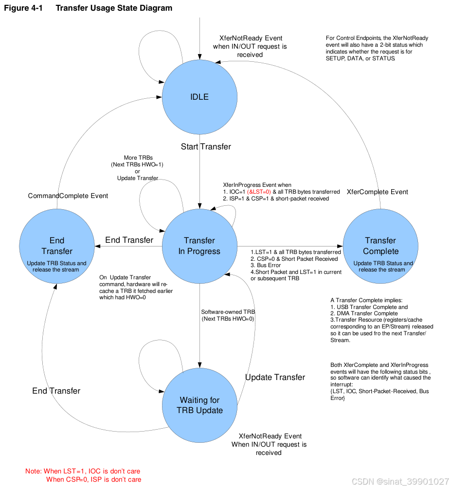
1.1.5 TRANSFER
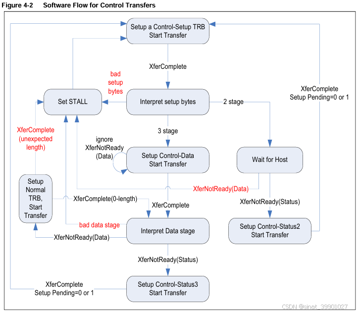
1.1.6 CTRL TRANSFER
1.1.7 ISOC transfer
The hardware will report the bus time that the host starts polling the endpoint inside the XferNotReady event. Software will use this value as a reference when issuing the Start Transfer command to serve as time synchronization with the host.
- Set up TRBs and data buffer for the endpoint.
- After configuring and enabling the endpoint, wait for an XferNotReady event. The XferNotReady event will contain the time that the host started polling the endpoint in the upper 16 bits.
- Issue the Start Transfer command to the endpoint with a future microframe time written into the upper 16 bits of the DEPCMD register.
The future microframe time must be a value that is an integral multiple of intervals after the time reported in the XferNotReady event and aligned to the beginning of an interval.
For example, if bInterval is 3 (4 microframes), and the XferNotReady time is 2, the value can be 4, 8, 12, and so on. The future microframe time must also be no greater than 4 seconds past the time reported in the XferNotReady event. - If the future microframe time has already passed when the command is received, the controller will respond with an error (bit 13 in the Command Complete event).
In this case, software must issue End Transfer, then wait for another XferNotReady event and attempt the command again with a time that is further in the future.
Otherwise, the first Buffer Descriptor will be used for the interval starting with the microframe time specified in the Start Transfer command.
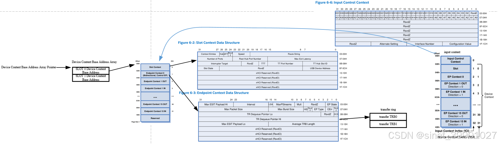
1.2 host
1.2.1 xhci 协议
二、SNPS VIP
timescale 需要是 1ps/1ps
2.1 基本传输
verilog
// control transfer
	// GET_DESCRIPTOR
    `uvm_create_on(usb_xfer[0], p_sequencer.svt_usb_transfer_sqr)
    usb_xfer[0].cfg  = post_enumeration_cfg;
    status = usb_xfer[0].randomize() with {
      xfer_type                           == svt_usb_transfer::CONTROL_TRANSFER;
      setup_data_bmrequesttype_dir        == svt_usb_types::DEVICE_TO_HOST;
      setup_data_bmrequesttype_type       == svt_usb_types::STANDARD;
      setup_data_bmrequesttype_recipient  == svt_usb_types::BMREQ_DEVICE;
      setup_data_brequest                 == svt_usb_types::GET_DESCRIPTOR;
      setup_data_w_value                  == 16'h0100;
      setup_data_w_index                  == 0;
      setup_data_w_length                 == 18;
    };
    `uvm_send(usb_xfer[0])
	l_agent.prot.NOTIFY_USB_TRANSFER_ENDED.wait_trigger();

	// SET_ADDRESS
      `uvm_create_on(usb_xfer[0], p_sequencer.svt_usb_transfer_sqr)
      usb_xfer[0].cfg  = pre_enumeration_cfg;
      status = usb_xfer[0].randomize() with {
        xfer_type                           == svt_usb_transfer::CONTROL_TRANSFER;
        setup_data_bmrequesttype_dir        == svt_usb_types::HOST_TO_DEVICE;
        setup_data_bmrequesttype_type       == svt_usb_types::STANDARD;
        setup_data_bmrequesttype_recipient  == svt_usb_types::BMREQ_DEVICE;
        setup_data_brequest                 == svt_usb_types::SET_ADDRESS;
        setup_data_w_value                  == 22;
        setup_data_w_index                  == 0;
        setup_data_w_length                 == 0;
      };
      `uvm_send(usb_xfer[0])
      p_sequencer.usb_env.host_agent.prot.NOTIFY_USB_TRANSFER_ENDED.wait_trigger();
	// vip 发送完 set address 之后需要reconfigure,设置 cfg 中的 dev addr,从而保证后续包中的dev addr是正确的
	if ($cast(post_enumeration_cfg, pre_enumeration_cfg.clone())) begin
        post_enumeration_cfg.remote_device_cfg[0].device_address = usb_xfer[0].get_setup_data_w_value_val();
        `uvm_info("body", "Host component about to be re-configured.", UVM_LOW)
        l_agent.reconfigure(post_enumeration_cfg);
        //post_enumeration_cfg.print();
        `uvm_info("body", "Host component is re-configured.", UVM_LOW)
      end
      else begin
        `uvm_fatal("body","Unable to $cast pre_enumeration_cfg to post_enumeration_cfg")
      end

// bulk transfer
        `uvm_create_on(usb_xfer[1], p_sequencer.svt_usb_transfer_sqr)
        usb_xfer[1].cfg  = post_enumeration_cfg;
        status = usb_xfer[1].randomize() with {
          xfer_type                              == svt_usb_transfer::BULK_IN_TRANSFER;
          payload_intended_byte_count            == 'h4000;
          aligned_transfer_ends_with_zero_length == 0;
        };
        // aligned_transfer_ends_with_zero_length == 0 时 传输总包长是最大包长整数倍时不需要额外发送零长包,
        // IN 时,vip会在收到总包长==payload_intended_byte_count 时认为传输完成,但是收到短包(包长<最大包长)时,也会认为传输完成,但会报 warning
        // 但是 payload_intended_byte_count % max_payload_size != 0 时,不能设置 aligned_transfer_ends_with_zero_length == 0; 会报错
        `uvm_send(usb_xfer[1])
        l_agent.prot.NOTIFY_USB_TRANSFER_ENDED.wait_trigger();

// isoc transfer
        `uvm_create_on(usb_xfer[1], p_sequencer.svt_usb_transfer_sqr)
        usb_xfer[1].cfg  = post_enumeration_cfg;
        status = usb_xfer[1].randomize() with {
          xfer_type                              == svt_usb_transfer::ISOCHRONOUS_IN_TRANSFER;
          payload_intended_byte_count            == 'h400;
          aligned_transfer_ends_with_zero_length == 0;
        };
        `uvm_send(usb_xfer[1])
        l_agent.prot.NOTIFY_USB_TRANSFER_ENDED.wait_trigger();
        // isoc transfer 比较特殊,需要依赖 sof 包计算 frame num ,但是 vip 默认是不发送 sof,需要手动开启
        svt_usb_protocol_service_20_sof_on_sequence sof_on_seq;
        wait (l_agent.shared_status.link_usb_20_state == svt_usb_types::ENABLED);
    	`uvm_info("body", "Enable SOF for isoc transfer.", UVM_LOW)
    	`uvm_do_on(sof_on_seq, l_agent.prot_service_sequencer);

// scale down
    void'(this.cfg.usb_cfg.host_cfg.set_timer_values(svt_usb_configuration::USB_VIP_SCALEDOWN_TIMER_VALUES));
    void'(this.cfg.usb_cfg.dev_cfg.set_timer_values(svt_usb_configuration::USB_VIP_SCALEDOWN_TIMER_VALUES));
	// 可能需要手动调整某些 timing 的值
    cfg.usb_cfg.dev_cfg.tinactivity = 1500000000;
2.2 Modifying USB 2.0 device VIP data response
https://solvnetplus.synopsys.com/s/article/USB-SVT-Modifying-Device-Data-Responses-1576091387967
A device VIP responds with default data (random or two seed based) for an IN transfer. If you modify the default data with user-defined data, then set up the VIP callbacks to modify the data. To change the payload, count and/or data generation algorithm, a VIP's response factories can also be used (instead of callbacks) to alter randomized_usb_20_transfer_response for 2.0 transfers.
Perform the following steps while using callbacks for modifying payload count and data:
- Extend the svt_usb_protocol_callbacks class and create a device response payload callbacks class.
- Use the pre_transfer_out_port_put method to update the payload_intended_byte_count. The member payload_intended_byte_count specifies the total payload byte count transferred. To modify total payload bytes, the following (3 and 4) steps can be ignored.
- Assign a payload object TWO_SEED_BASED_ALGORITHM_wt attribute to zero, and the USER_DEFINED_ALGORITHM_wt attribute to a positive integer.
- Use the randomized_transfer_complete_response callback method to modify the VIP generated data with the user-defined data.
- Append the callbacks class object with a device VIP.
UVM code snippet for BULK IN transfers is as follows:
class usb_device_response_payload_callbacks extend svt_usb_protocol_callbacks;

  virtual function void pre_transfer_out_port_put (svt_usb_protocol component, int chan_id, ref svt_usb_transfer transfer, ref bit drop);
    begin
      if (transfer.get_xfer_type_val() == svt_usb_transfer::BULK_IN_TRANSFER) begin
              transfer.payload_intended_byte_count = 4;
              transfer.payload.TWO_SEED_BASED_ALGORITHM_wt = 0;
              transfer.payload.USER_DEFINED_ALGORITHM_wt = 1;
      end
      if (transfer.get_xfer_type_val() == svt_usb_transfer::CONTROL_TRANSFER && transfer.get_setup_data_bmrequesttype_dir_val()== svt_usb_types::DEVICE_TO_HOST) begin
               transfer.payload.TWO_SEED_BASED_ALGORITHM_wt = 0;
               transfer.payload.USER_DEFINED_ALGORITHM_wt = 1;
      end
   end
endfunction // pre_transfer_out_port_put

  virtual function void randomized_transfer_complete_response (svt_usb_protocol component, svt_usb_transfer transfer);
    begin
           if (transfer.get_xfer_type_val() == svt_usb_transfer::BULK_IN_TRANSFER) begin
             /**
              * Override the random values, payload array, with user-defined values
              */
              foreach(transfer.payload.data[i])
                transfer.payload.data[i] = i;

          end
  		 // if transfer == bulk IN
         if (transfer.get_xfer_type_val() == svt_usb_transfer::CONTROL_TRANSFER && transfer.get_setup_data_bmrequesttype_dir_val()== svt_usb_types::DEVICE_TO_HOST) begin
         /**
          * Override the random values, payload array, with user-defined values
          */
          foreach(transfer.payload.data[i])
            transfer.payload.data[i] = i;
         end
    end
  endfunction // randomized_transfer_complete_response
endclass
2.3 usb vip 注错
usb vip callback 分为 protocol_callback 和 physical_callback, 分别实现不同层级的注错,定义好callback之后 在sequence 中需要的地方注册到相应的组件中
system
uvm_callbacks#(svt_usb_physical)::add(l_agent.phys, host_bit_cb);
uvm_callbacks#(svt_usb_protocol)::add(l_agent.prot, pro_cb);

class my_protocol_callbacks extends svt_usb_protocol_callbacks;
  `svt_xvm_object_utils(my_protocol_callbacks)
  int error_injection_count;
  svt_usb_packet_exception  packet_exc = new();

  virtual function void pre_usb_20_packet_out_port_put(  svt_usb_protocol component , int chan_id , svt_usb_packet packet ,
                                                         svt_usb_transaction transaction , int packet_ix , svt_usb_transfer transfer ,
                                                         int transaction_ix , ref bit drop  ) ;

  `ifdef PID_ERROR
  if(error_injection_count==0)begin
    //$display("inject pid error");
    error_injection_count++;
    packet_exc.error_kind = svt_usb_packet_exception::PID_CHECK_ERROR;
    packet_exc.xact = packet;
    packet.exception_list = new();
    packet.exception_list.add_exception(packet_exc);
  end
  `endif

  endfunction
endclass

class my_physical_callbacks extends svt_usb_physical_callbacks;
  int error_injection_count = 0;
  bit data_byte= 1'b0;
  static int packet_count = 0;

  //Factory Registration
  `svt_xvm_object_utils(hs_rx_error_data_error_callbacks )

  svt_usb_data_exception  data_exc_temp  = new();
  svt_usb_data_exception_list data_exec_list =new();

  //--------------------------------------------------------------------
  function new(string name="hs_rx_error_data_error_callbacks ");
    super.new (name);
  endfunction

  //----------------------------------------------------------------------------------------------------
  virtual function void post_usb_20_link_data_in_port_get(svt_usb_physical component, int chan_id, svt_usb_data data, ref bit drop);
      svt_usb_data l_data;
      int i;
      l_data = data;

      `ifdef BIT_STUFF_ERROR
      if((data.is_eop) && (error_injection_count<5)) begin
        error_injection_count++;
        // second eop inject error
        if(error_injection_count==2) begin
          //$display("inject bit_stuff_error");
          data.eop_length=0;
          `svt_xvm_note("post_usb_20_link_data_in_port_get", $psprintf("Injection at data stage time: %t",$time));
          data_exc_temp.error_kind = svt_usb_data_exception::BYTE_ERROR;
          data_exc_temp.byte_error= svt_usb_data_exception::LONG_BYTE_ERROR;
          data_exc_temp.byte_length=16;
          data_exc_temp.byte_pattern=new[16];
          data_exc_temp.byte_pattern[0]=svt_usb_types::LINESTATE_J;
          for(i=1;i<9;i++) begin
            data_exc_temp.byte_pattern[i]=svt_usb_types::LINESTATE_K;
          end
          for(i=9;i<16;i++) begin
            data_exc_temp.byte_pattern[i]=svt_usb_types::LINESTATE_SE0;
          end
          data.exception_list = new();
          data.exception_list.add_exception(data_exc_temp);
         `svt_note("hs_rx_error_data_error_callbacks::post_usb_20_link_data_in_port_get()",$sformatf("Exception_inserted: %0s subtype : %0s  ",data_exc_temp.error_kind.name,data_exc_temp.bit_stuff_error.name));
        end
      end

      `elsif EOP_ERROR
      if((data.is_eop) && (error_injection_count<5)) begin
        error_injection_count++;
        if((l_data.is_eop == 1'b1) && (error_injection_count == 2)) begin
          //$display("inject eop error");
          data_exc_temp.error_kind = svt_usb_data_exception::EOP_ERROR;
          data_exc_temp.eop_error = svt_usb_data_exception::SHORT_EOP_ERROR;
          data_exc_temp.eop_length = 0;
          data_exc_temp.xact = data;
          data.exception_list = new();
          data.exception_list.add_exception(data_exc_temp);
          `svt_note("svt_usb_hs_no_eop_error_callbacks::post_usb_20_link_data_in_port_get()",$sformatf("Exception_inserted: %0s subtype : %0s  ",data_exc_temp.error_kind.name, data_exc_temp.eop_error.name));
          //`uvm_info("build_phase", $sformatf("post_usb_20_physical_data_in_port_get:\n%s", data.`SVT_DATA_PSDISPLAY(" DATA: ")), UVM_LOW);
        end
      end

      `elsif SYNC_ERROR
      //if((data.is_eop) && (error_injection_count<5)) begin
      //  error_injection_count++;
        if(error_injection_count == 0) begin
          //$display("inject sync error");
          error_injection_count++;
          data_exc_temp.error_kind = svt_usb_data_exception::SYNC_ERROR;
          data_exc_temp.sync_error = svt_usb_data_exception::SHORT_SYNC_ERROR;
          data_exc_temp.sync_length = 0;
          data_exc_temp.xact = data;
          data.exception_list = new();
          data.exception_list.add_exception(data_exc_temp);
          `svt_note("svt_usb_hs_no_eop_error_callbacks::post_usb_20_link_data_in_port_get()",$sformatf("Exception_inserted: %0s subtype : %0s  ",data_exc_temp.error_kind.name, data_exc_temp.sync_error.name));
          //`uvm_info("build_phase", $sformatf("post_usb_20_physical_data_in_port_get:\n%s", data.`SVT_DATA_PSDISPLAY(" DATA: ")), UVM_LOW);
        end
        //end

      `elsif UNDERFLOW_ERROR
      if((l_data.is_sop != 1'b1) && (error_injection_count< 300)) begin
        tb.U_VIP.usb_test_top.jitter_clk =1'b1;
        //tb.U_VIP.usb_test_top.jitter_high_freq_clk =1'b1;
        `svt_xvm_note("body",$psprintf("\n\n Jitter clk start time %t error_injection_count is %0d",$time, error_injection_count));
        error_injection_count++;
      end
      else if((l_data.is_eop ==1'b1))begin
         tb.U_VIP.usb_test_top.jitter_clk =1'b0;
        `svt_xvm_note("body",$psprintf("\n\n Jitter clk end time %t",$time));
        packet_count++;
      end

      `elsif OVERFLOW_ERROR
      if((l_data.is_sop != 1'b1) &&  error_injection_count< 300) begin
        tb.U_VIP.usb_test_top.jitter_clk =1'b1;
        tb.U_VIP.usb_test_top.jitter_high_freq_clk =1'b1;
        //`svt_xvm_note("body",$psprintf("\n\n Jitter clk start time %t error_injection_count is %0d",$time, error_injection_count));
        error_injection_count++;
      end
      else if((l_data.is_eop ==1'b1))begin
         tb.U_VIP.usb_test_top.jitter_clk =1'b0;
        `svt_xvm_note("body",$psprintf("\n\n Jitter clk end time %t",$time));
        packet_count++;
      end
    `endif
  endfunction
endclass : hs_rx_error_data_error_callbacks
2.4 link service cmd
system
      `uvm_create_on(link_service_command, p_sequencer.link_service_sequencer)
      link_service_command.service_type = svt_usb_link_service::LINK_20_PORT_COMMAND;
      link_service_command.link_20_command_type = svt_usb_link_service::USB_20_PORT_RESET;
      // link_service_command.prereq_link_20_state = svt_usb_types::ENABLED;  ???
      //This field is used to figure out whether the service request should start immediately or wait for the link layer to be in a particular 20 link state before starting the request. If set to 'ENABLED' it indicates that any link 20 host state is acceptable for starting the service request. Any other values require that the link layer get to that 20 state prior to starting the request. Only used if service_type set to LINK_COMMAND or LINK_20_PORT_COMMAND. Occurs prior to prereq_link_20_delay and in parallel with link_service_delay.
      link_service_command.cfg = post_enumeration_cfg;
      link_service_command.print();
      `uvm_send(link_service_command)
      link_service_command.end_event.wait_on();
2.5 others
usb_base_test.sv 中会设置 svt_usb_transfer override 为 cust_svt_usb_transfer,改变 isoc transfer 权重,导致报错
set_inst_override_by_type("env.host_agent.xfer_sequencer.*",svt_usb_transfer::get_type(),cust_svt_usb_transfer::get_type());
u_DWC_usb3.U_DWC_usb3_noclkrst.U_DWC_usb3_pwrdwn.U_DWC_usb3_u2pwrdwn.hmacs.insthmac0.U_DWC_usb3_u2hmac.U_DWC_usb3_u2mac.tkn_state1:0
u_DWC_usb3.U_DWC_usb3_noclkrst.U_DWC_usb3_pwrdwn.U_DWC_usb3_u2pwrdwn.hmacs.insthmac0.U_DWC_usb3_u2hmac.U_DWC_usb3_u2mac.txrx_state4:0
u_DWC_usb3.U_DWC_usb3_noclkrst.U_DWC_usb3_pwrdwn.U_DWC_usb3_tr.atr_evts16:0