STM32C5开发IIS3DWB10IS.2--IIC获取震动计数据
- 概述
- 视频教程
- 样品申请
- 源码下载
- 硬件准备
- 参考程序
- 串口配置
- 通信模式
- 管脚定义
- SPI通信模式
- SPI配置
- CS设置
- 生成项目
- 导入STM32CubeIDE
- 设置工程编码
- 参考程序
- CMake设置
- 头文件设置
- 变量定义
- [设置 CS、SA0 和器件地址](#设置 CS、SA0 和器件地址)
- 串口发送与延时
- 绑定驱动接口
- 配置量程和输出数据率
- 读取并显示数据
- 运行效果
概述
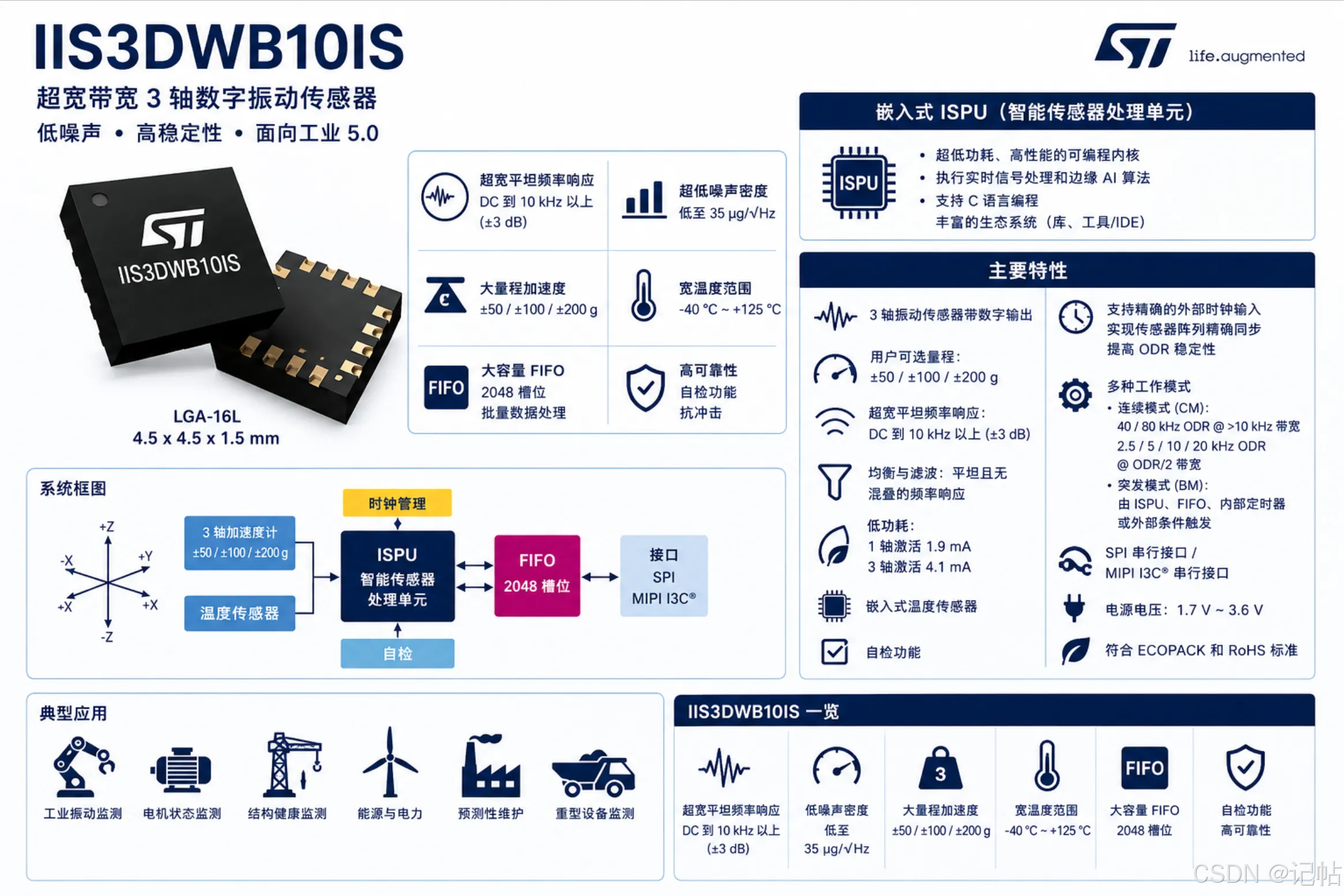
本章介绍如何使用 STM32C542CCT6 通过 IIC 接口驱动 IIS3DWB10IS,实现三轴加速度和温度数据的轮询读取。内容包括硬件连接、CubeMX 外设配置、驱动接口移植以及传感器初始化,并完成量程和输出数据率设置。采集到的原始数据经过单位换算后,通过 USART1 输出到串口调试助手,便于观察数据变化,为后续振动监测应用开发提供基础。
需要样片的可以加qun申请:925643491 / 615061293 。
视频教程
https://www.bilibili.com/video/BV1ADeq6YEky/
样品申请
https://www.wjx.top/vm/OhcKxJk.aspx#
源码下载
硬件准备
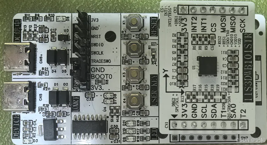
首先需要准备一个开发板,这里我准备的是自己绘制的开发板,需要的可以进行申请。
主控为STM32C542CC,振动传感器为IIS3DWB10IS。
参考程序
https://github.com/CoreMaker-lab/STM32C542CC_IIS3DWB10IS
https://gitee.com/CoreMaker/STM32C542CC_IIS3DWB10IS
串口配置
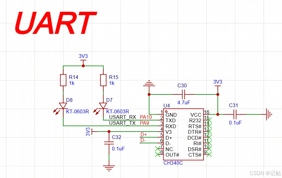
查看原理图,PA9和PA10设置为开发板的串口。
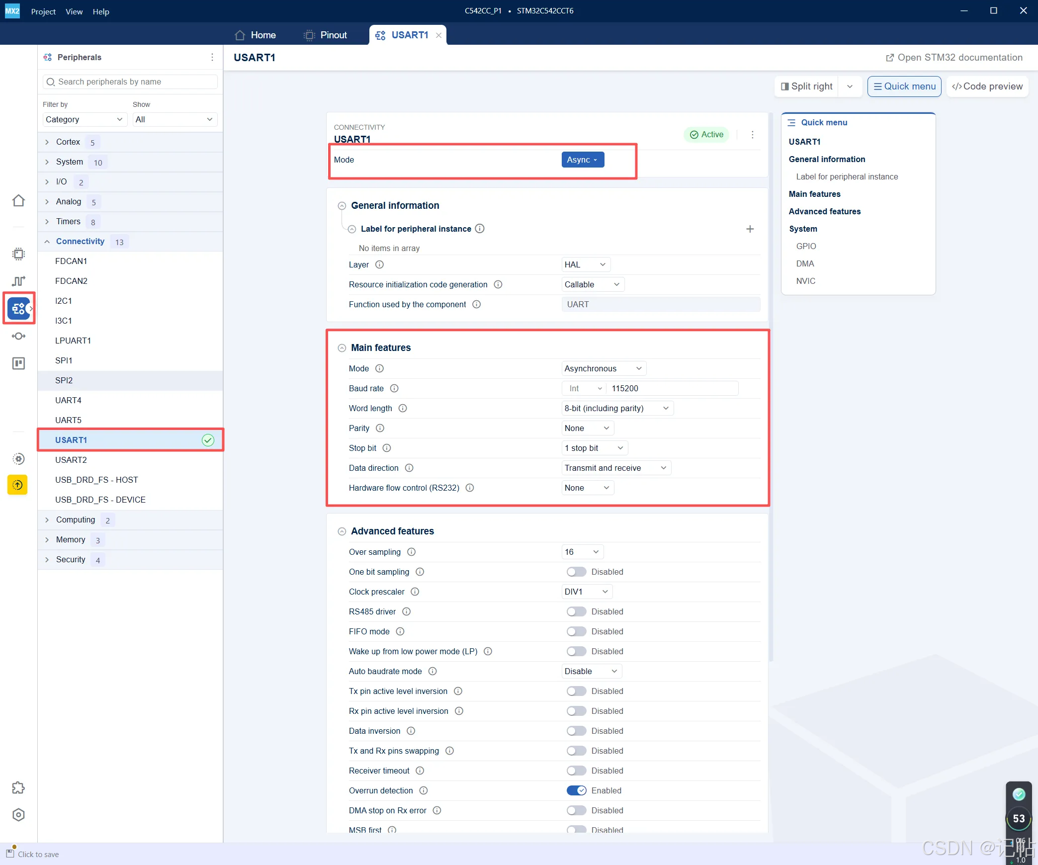
- 在左侧 Peripherals 中选择 Connectivity → USART1
- Mode 选择 Async,表示配置为异步串口模式
- Function used by the component 显示为 UART,说明 USART1 在异步模式下使用 UART HAL 驱动
- 串口参数配置为:115200 波特率、8 位数据位、无校验、1 位停止位、收发模式
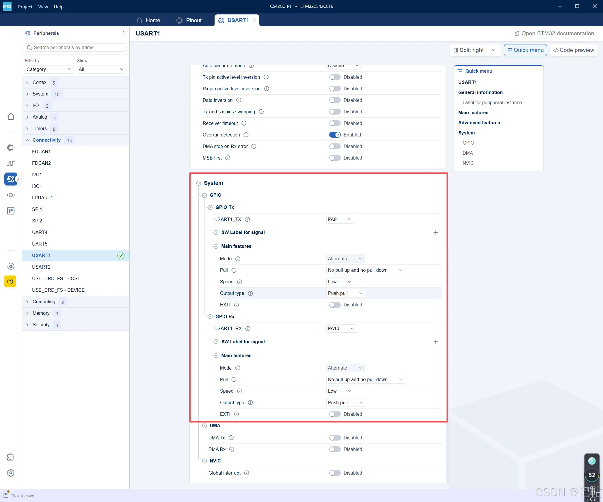
- GPIO Tx:USART1_TX 选择 PA9
- GPIO Rx:USART1_RX 选择 PA10
- PA9 / PA10 均配置为 Alternate 复用功能模式
- Pull 选择 No pull-up and no pull-down,Output type 选择 Push pull,Speed 选择 Low
通信模式
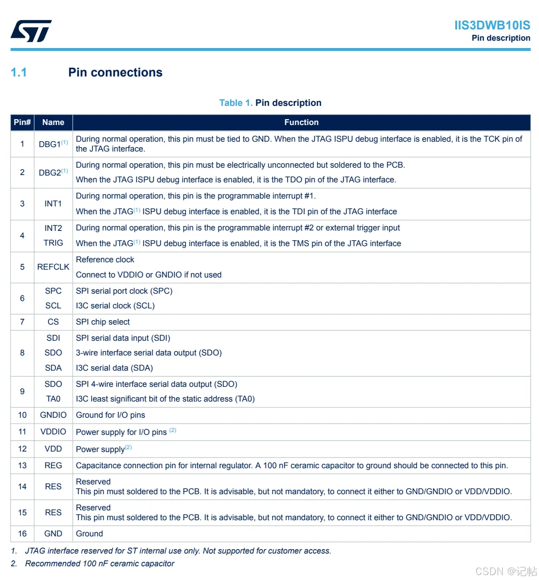
对于IIS3DWB10IS,可以使用SPI或者IIC进行通讯。
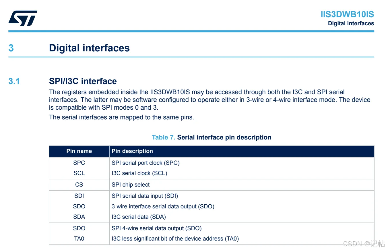
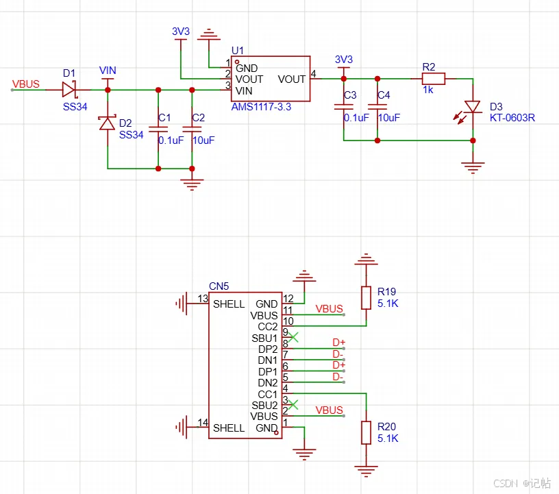
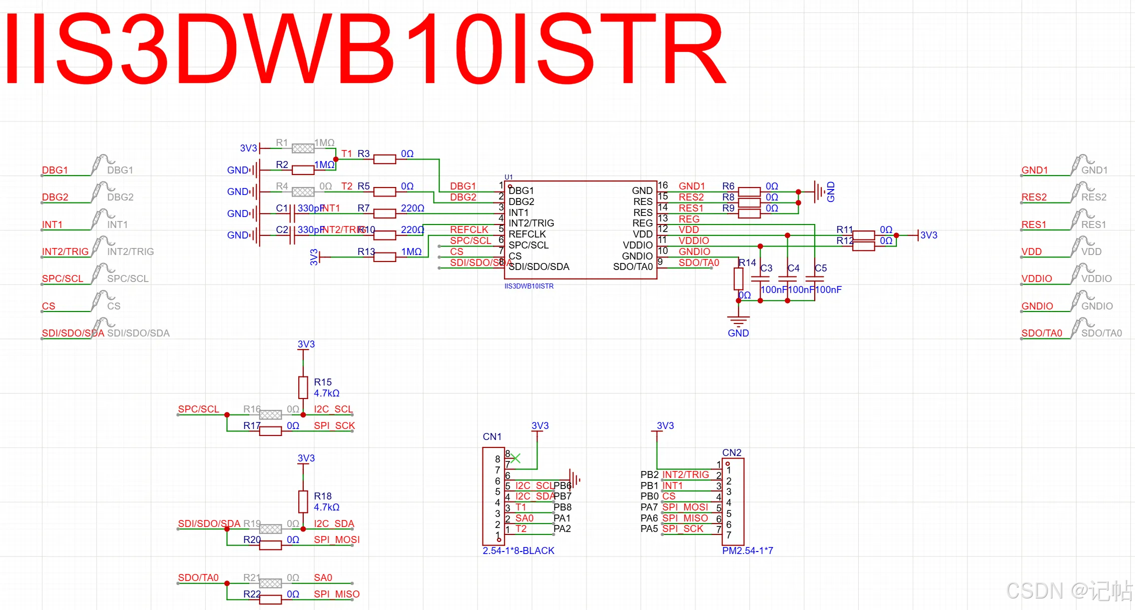
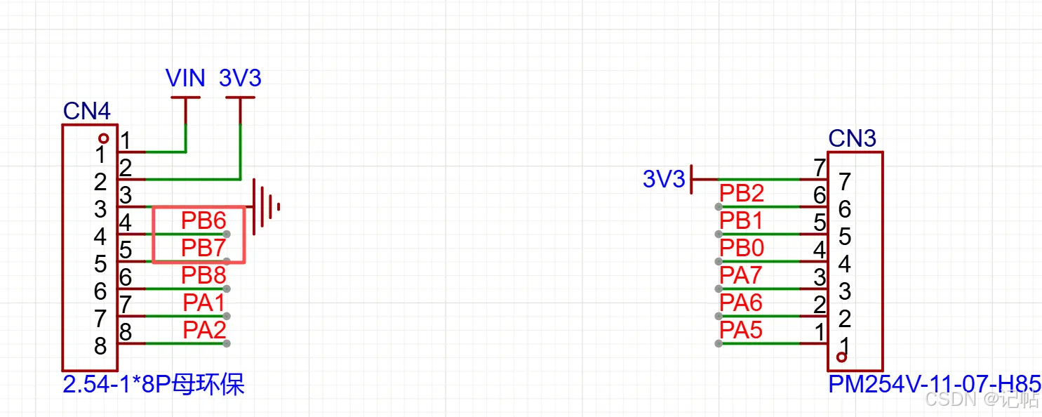
本文使用的板子原理图如下所示。
管脚定义
SPI通信模式
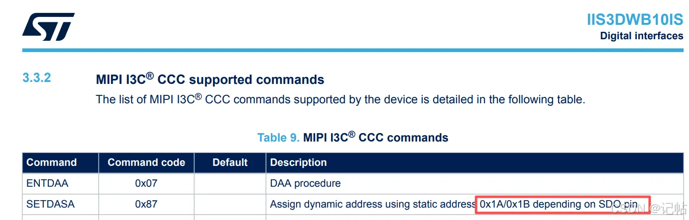
静态地址为 0x1A / 0x1B,取决于 SDO 引脚状态。
SPI配置
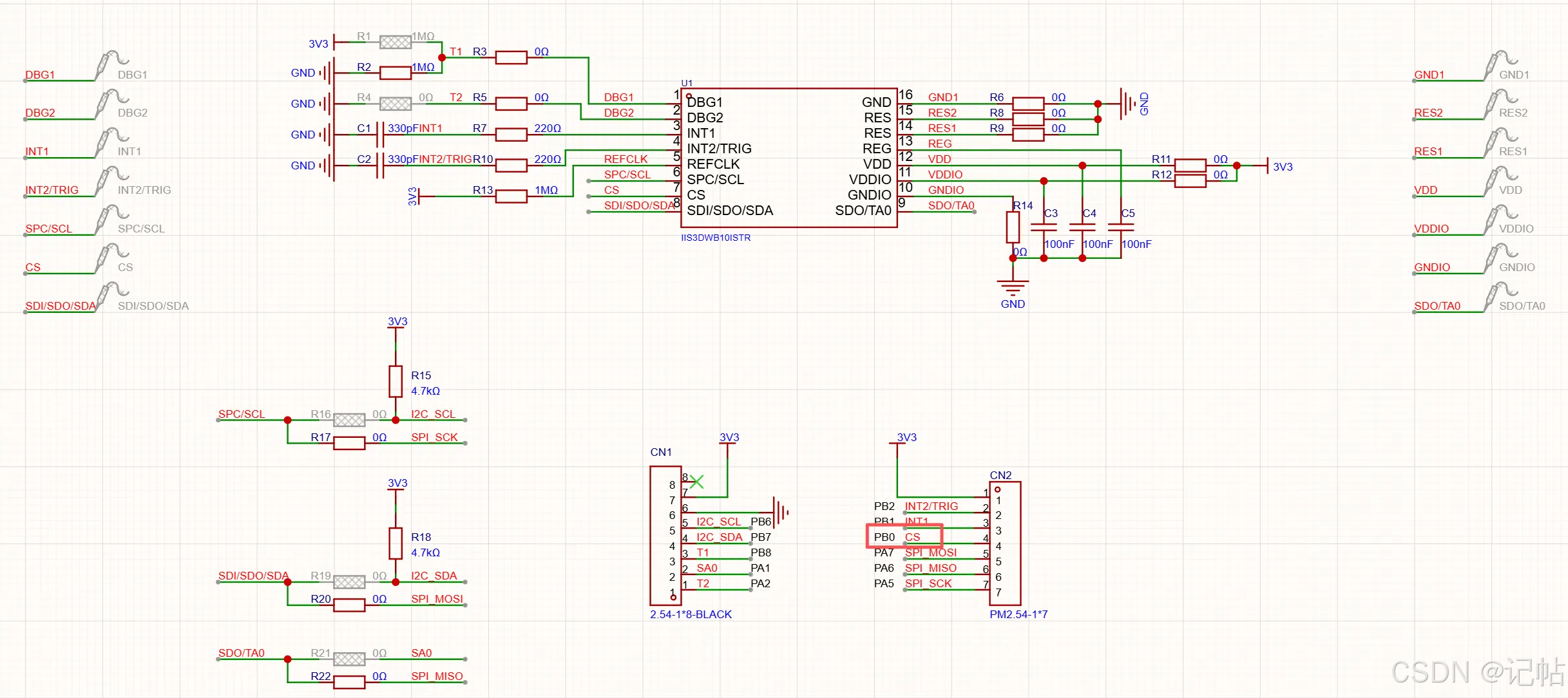
IIS3DWB10IS 通过 IIC(I²C)接口与 STM32C542CCT6 进行通信。传感器的 SPC/SCL 和 SDI/SDO/SDA 分别连接到 STM32C542CCT6 的 PB6 和 PB7,对应 I2C_SCL 时钟信号和 I2C_SDA 数据信号。SCL 和 SDA 均通过 4.7 kΩ 电阻上拉至 3.3 V。
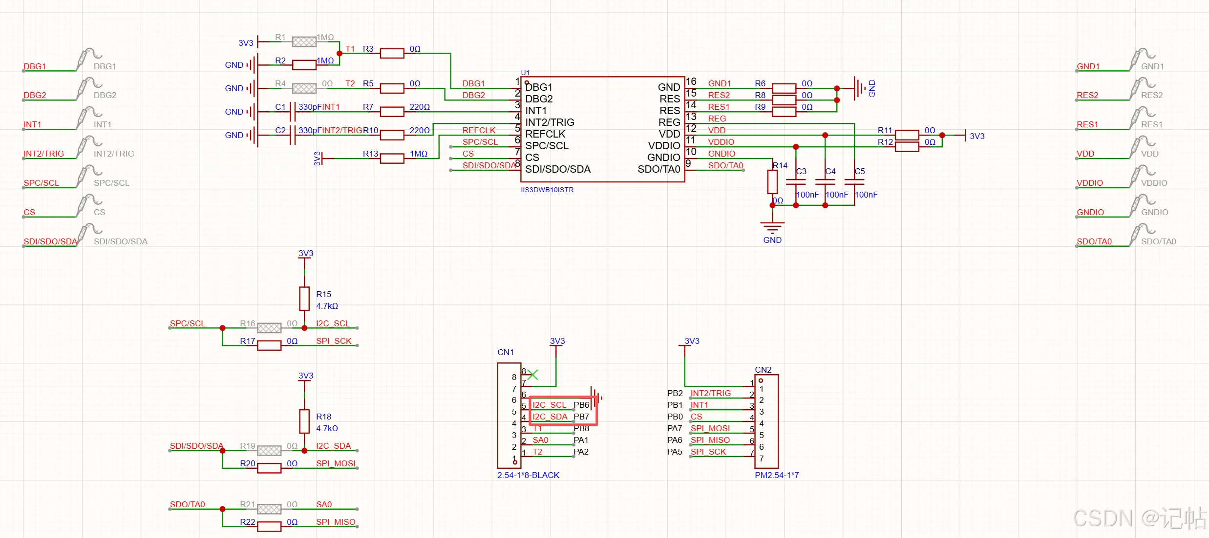
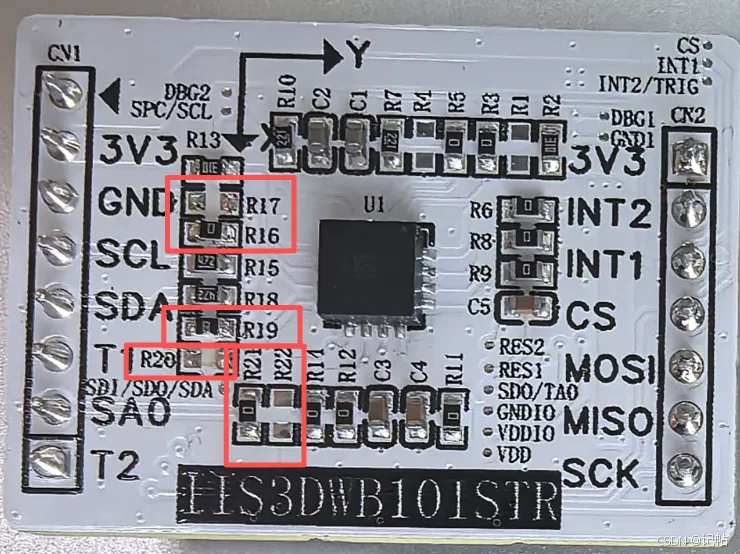
原理图通过 0 Ω 电阻实现 SPI 与 I3C 接口切换。使用 IIC 时,应焊接 R16、R19 和 R21,不焊接 R17、R20 和 R22。
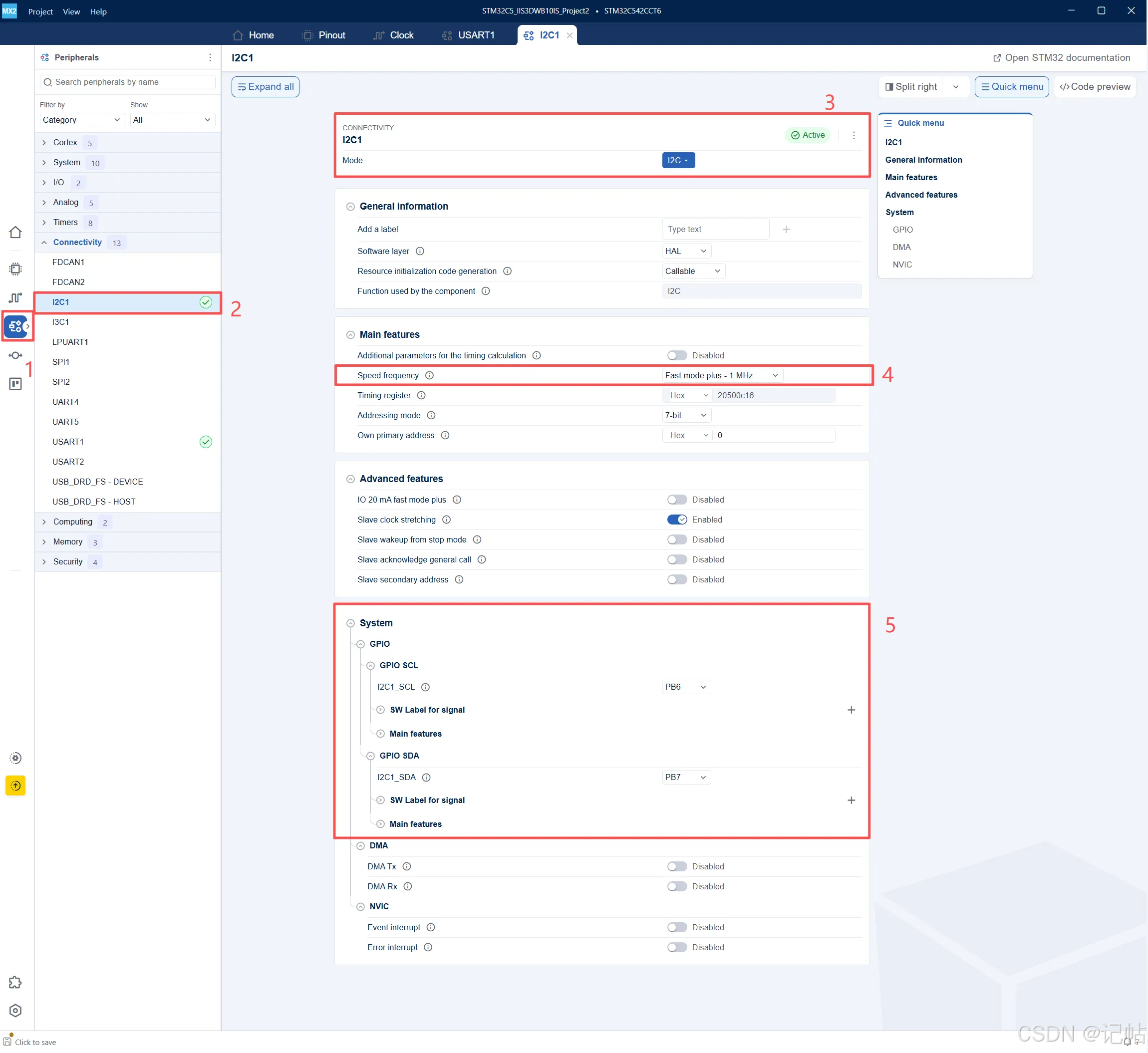
首先在 STM32CubeMX2 中进入 Peripherals 外设配置页面,在 Connectivity 分类中选择 I2C1,并将 I2C1 外设使能。
如图所示,本实验的 I2C1 配置步骤如下:
- 点击左侧 Peripherals 外设配置入口
- 在 Connectivity 分类中选择 I2C1
- 将 I2C1 Mode 设置为 I2C,并确认 I2C1 显示为 Active
- Speed frequency 设置为 Fast mode plus - 1 MHz
- 确认 I2C1 的 GPIO 引脚映射,SCL 为 PB6,SDA 为 PB7
CS设置
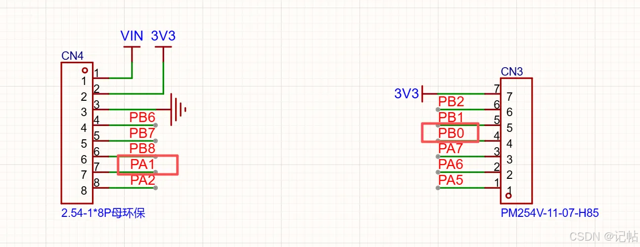
IIS3DWB10IS 的 CS 引脚连接到 STM32C542CCT6 的 PB0,SDO/TA0 引脚通过板上的 SA0 信号连接到 PA1。
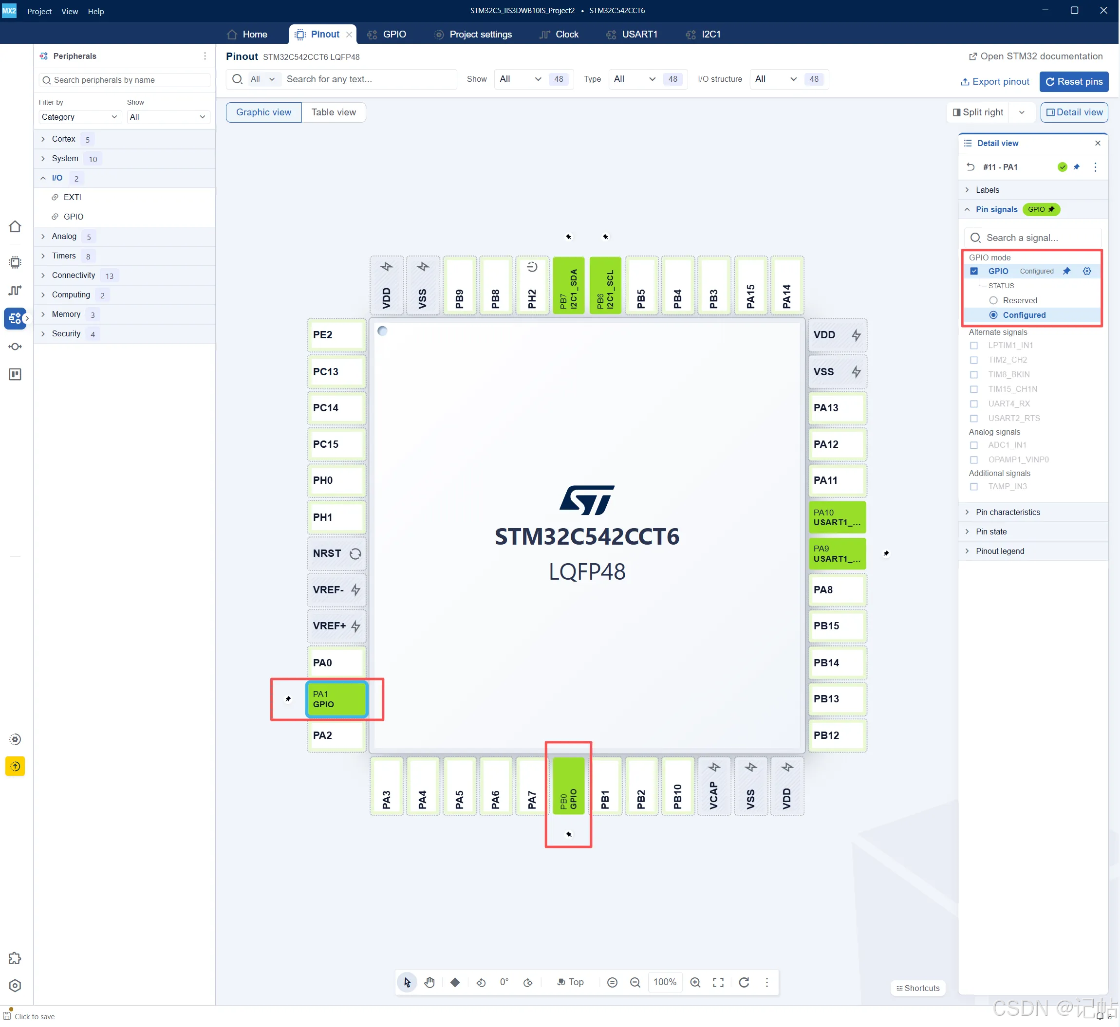
在 STM32CubeMX 的 Pinout 页面中选中PA1和 PB0,在右侧勾选 GPIO,并将状态设置为 Configured,作为 IIS3DWB10IS 的 CS 控制引脚。
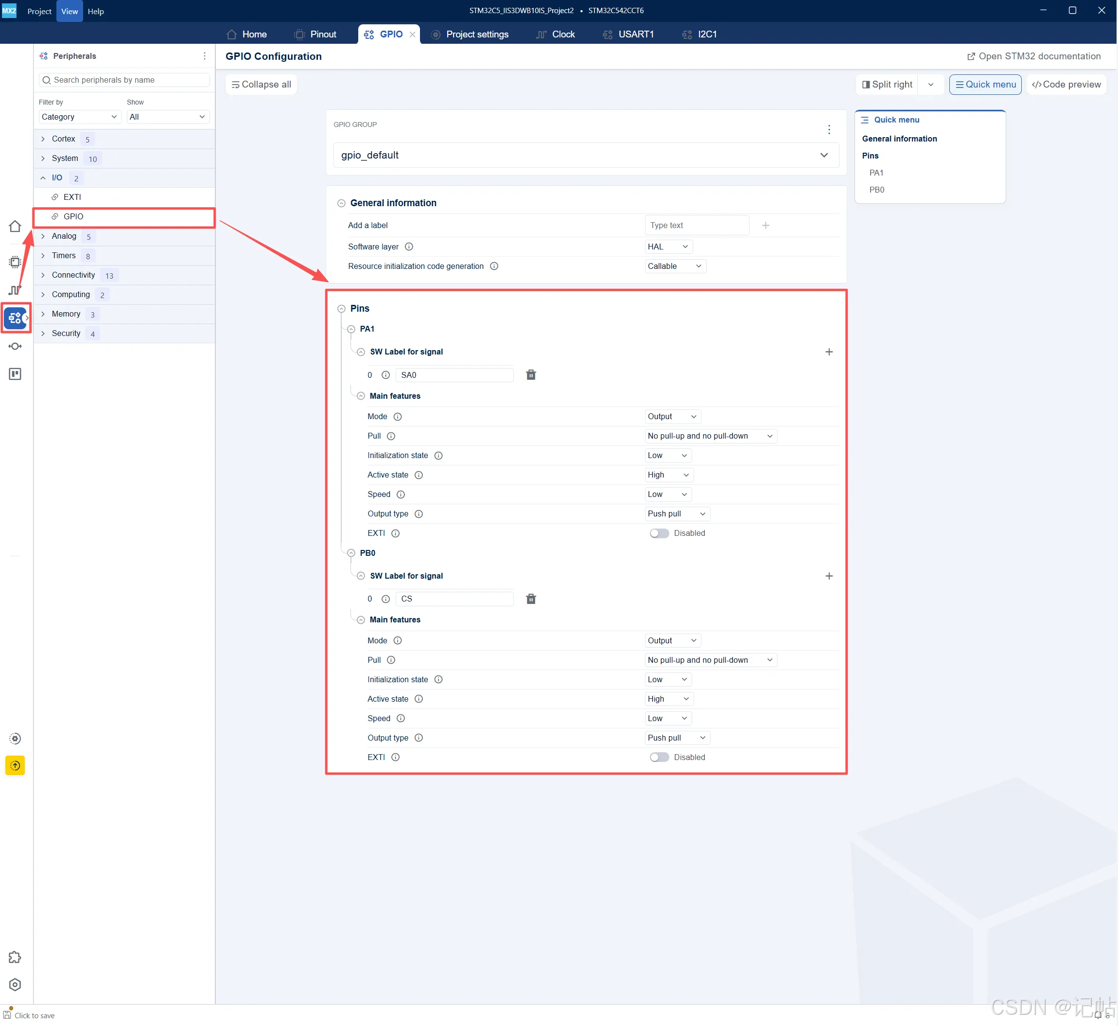
进入左侧 GPIO 配置页面,展开PA1和 PB0,将信号标签设置为SA0和 CS。引脚配置为输出模式(Output)。
生成项目
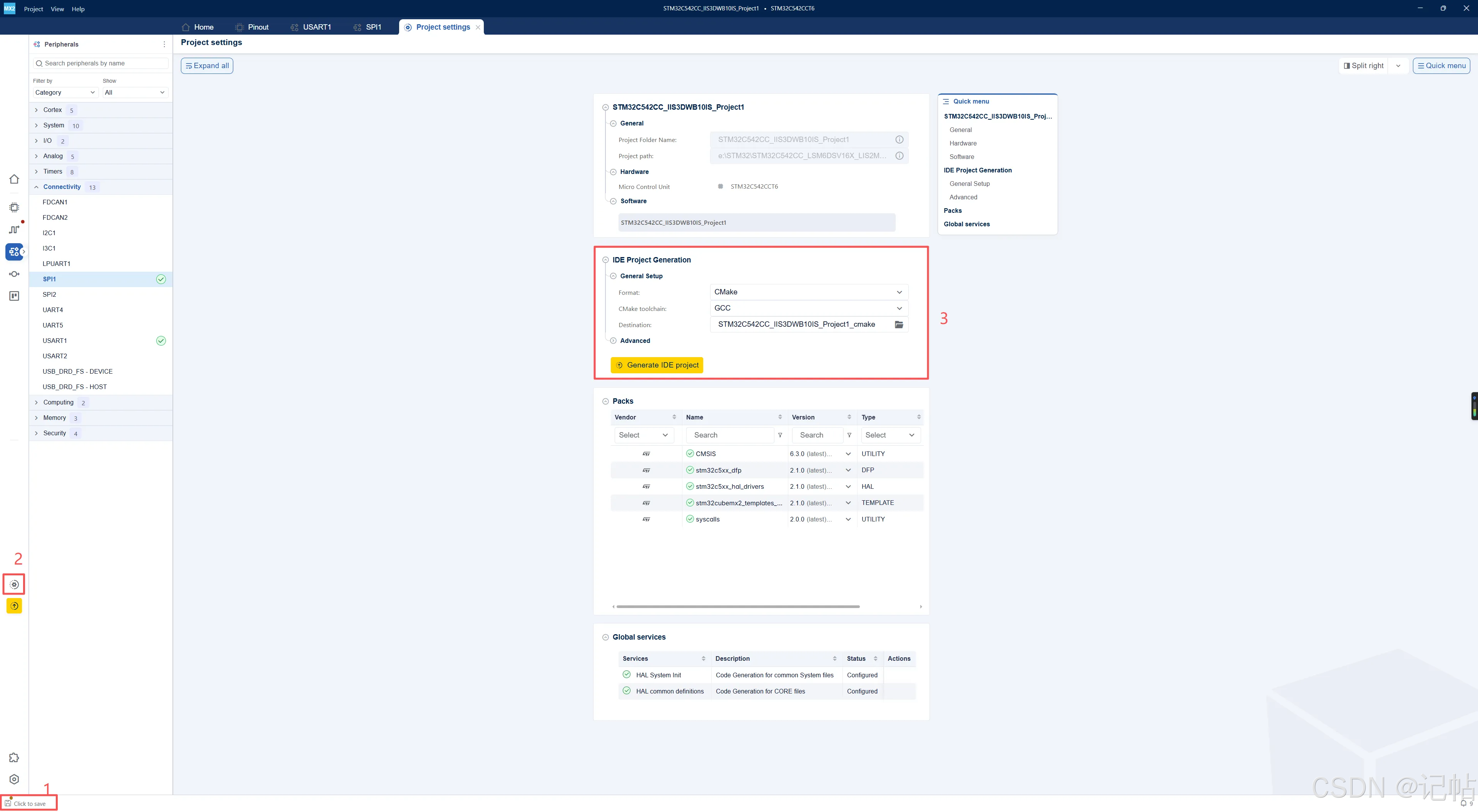
- 修改配置后,左下角会提示 Click to save,需要先保存当前工程配置
- 点击左侧 Project settings,进入工程生成设置页面
- 在 IDE Project Generation 中选择工程格式和工具链,本例选择 CMake + GCC,然后点击 Generate IDE project 生成工程
导入STM32CubeIDE
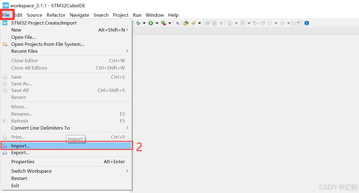
- 打开 STM32CubeIDE,点击菜单栏 File
- 选择 Import...,准备导入 STM32CubeMX2 生成的 CMake 工程
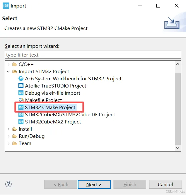
- 在 Import 窗口中展开 Import STM32 Project
- 选择 STM32 CMake Project
- 点击 Next,进入 CMake 工程路径选择页面
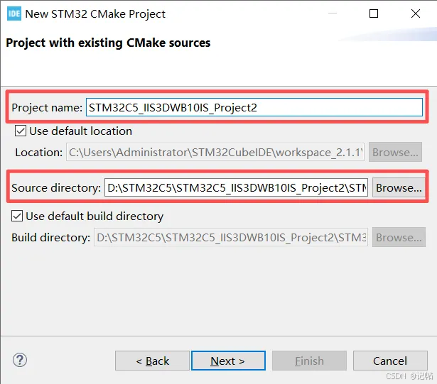
- Project name:填写导入到 STM32CubeIDE 中显示的工程名称
- Source directory:选择 STM32CubeMX2 生成的 CMake 工程目录
- 点击 Next,继续完成工程导入
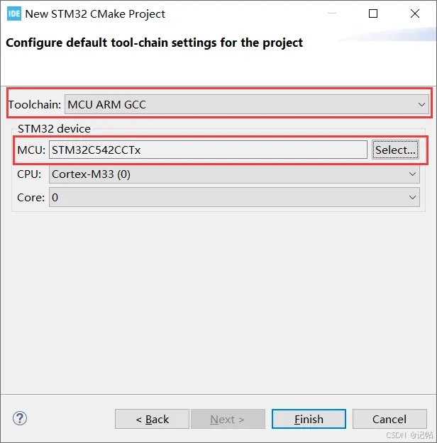
- Toolchain:选择 MCU ARM GCC,表示使用 ARM GCC 工具链进行编译
- MCU:确认芯片型号为 STM32C542CCTx,与前面 STM32CubeMX2 中选择的 MCU 保持一致
- CPU/Core:确认内核为 Cortex-M33,Core 为 0
- 点击 Finish,完成 CMake 工程导入
设置工程编码
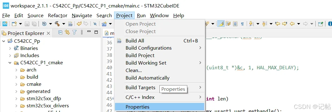
- 在 Project Explorer 中选中当前工程
- 点击菜单栏 Project
- 选择 Properties,进入工程属性设置
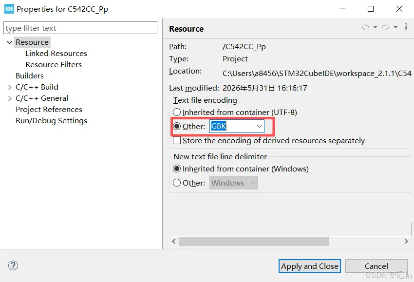
- 在工程属性中选择 Resource
- Text file encoding 选择 Other
- 编码格式输入 GBK
- 点击 Apply and Close 保存设置
参考程序
https://github.com/STMicroelectronics/iis3dwb10is-pid
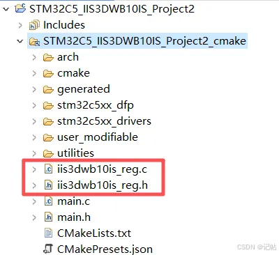
添加对应驱动程序。
CMake设置
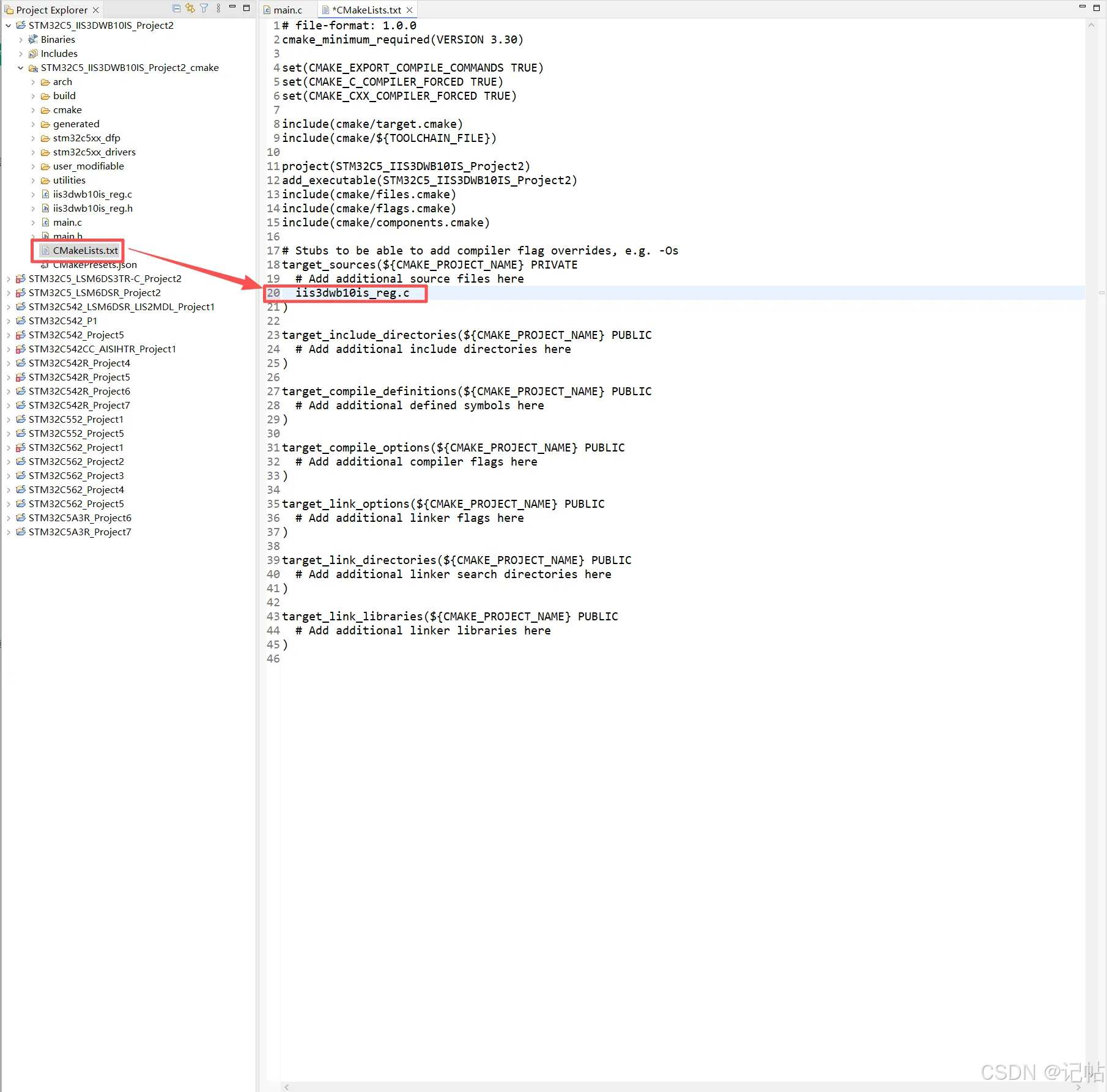
把iis3dwb10is_reg.c 加入 CMake 编译 。
c
# Stubs to be able to add compiler flag overrides, e.g. -Os
target_sources(${CMAKE_PROJECT_NAME} PRIVATE
  # Add additional source files here
  iis3dwb10is_reg.c
)
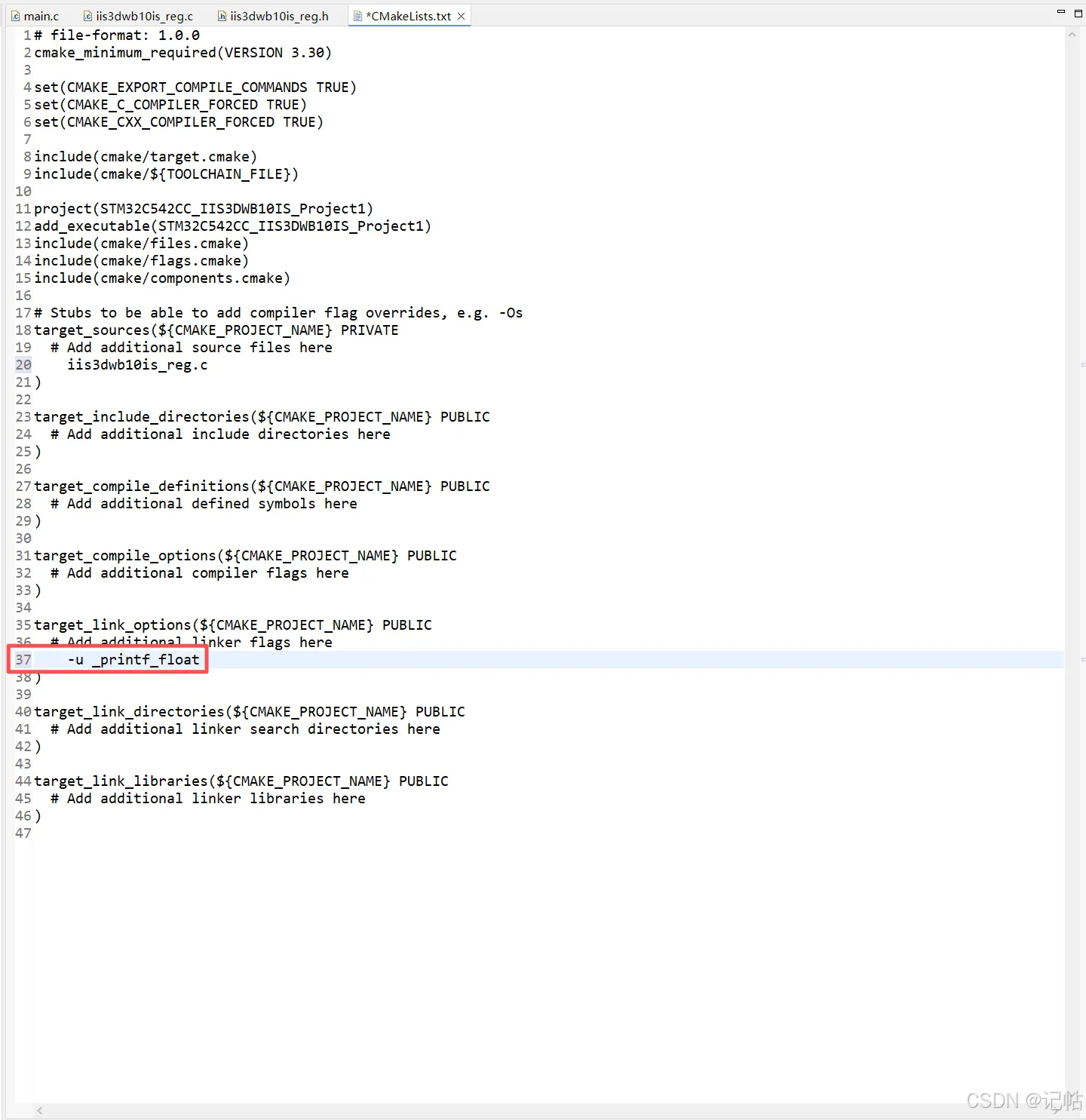
printf 输出浮点数需要额外开启 float printf 支持。
CMake 官方说明 target_link_options() 就是给可执行目标添加 linker options 的命令。
c
target_link_options(${CMAKE_PROJECT_NAME} PUBLIC
  # Add additional linker flags here
  -u _printf_float
)
头文件设置
添加头文件。
c
#include "iis3dwb10is_reg.h"
#include <stdio.h>
#include <string.h>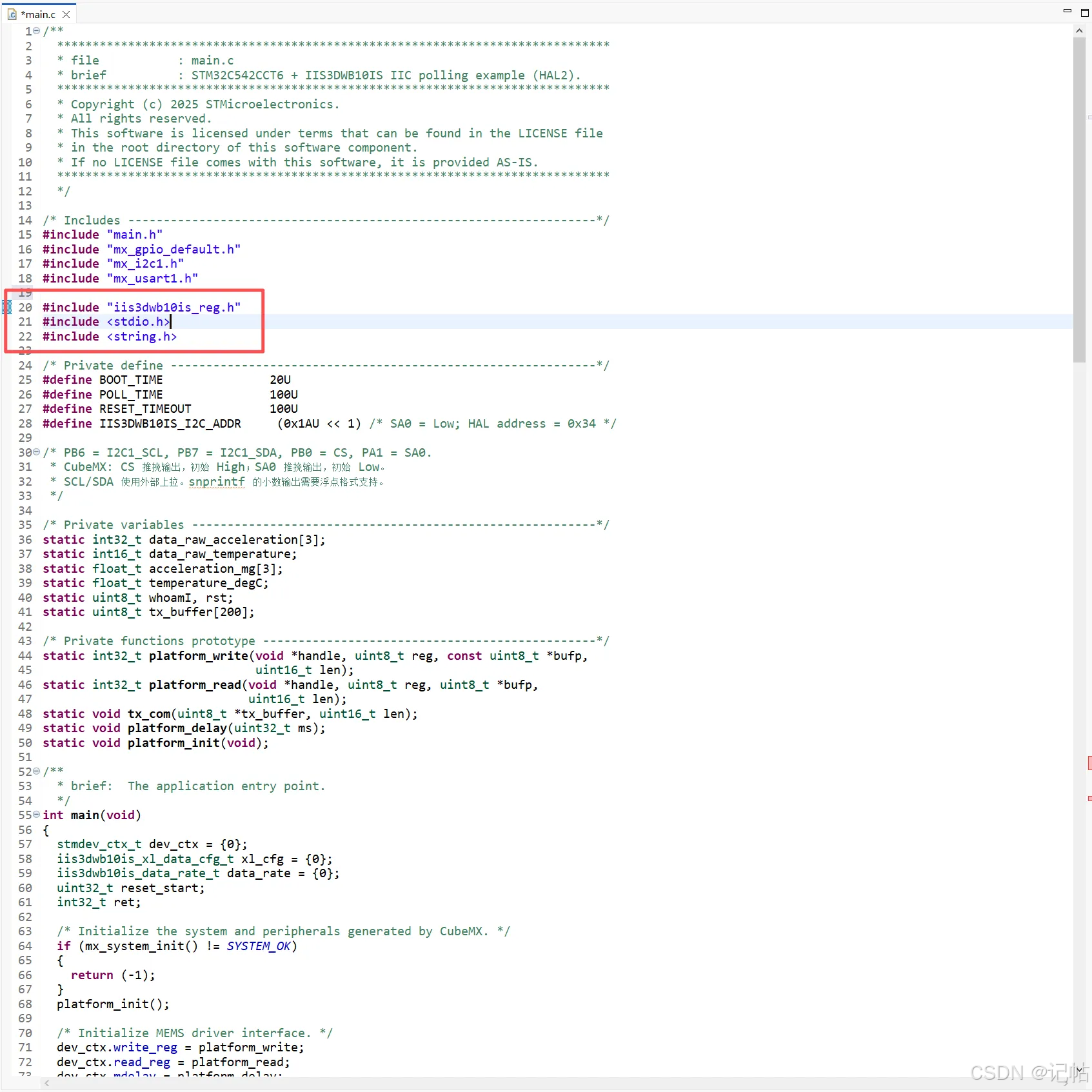
变量定义
c
/* Private define ------------------------------------------------------------*/
#define BOOT_TIME               20U
#define POLL_TIME               100U
#define RESET_TIMEOUT           100U
#define IIS3DWB10IS_I2C_ADDR     (0x1AU << 1) /* SA0 = Low; HAL address = 0x34 */

/* PB6 = I2C1_SCL, PB7 = I2C1_SDA, PB0 = CS, PA1 = SA0.
 * CubeMX: CS 推挽输出,初始 High;SA0 推挽输出,初始 Low。
 * SCL/SDA 使用外部上拉。snprintf 的小数输出需要浮点格式支持。
 */

/* Private variables ---------------------------------------------------------*/
static int32_t data_raw_acceleration[3];
static int16_t data_raw_temperature;
static float_t acceleration_mg[3];
static float_t temperature_degC;
static uint8_t whoamI, rst;
static uint8_t tx_buffer[200];

/* Private functions prototype -----------------------------------------------*/
static int32_t platform_write(void *handle, uint8_t reg, const uint8_t *bufp,
                              uint16_t len);
static int32_t platform_read(void *handle, uint8_t reg, uint8_t *bufp,
                             uint16_t len);
static void tx_com(uint8_t *tx_buffer, uint16_t len);
static void platform_delay(uint32_t ms);
static void platform_init(void);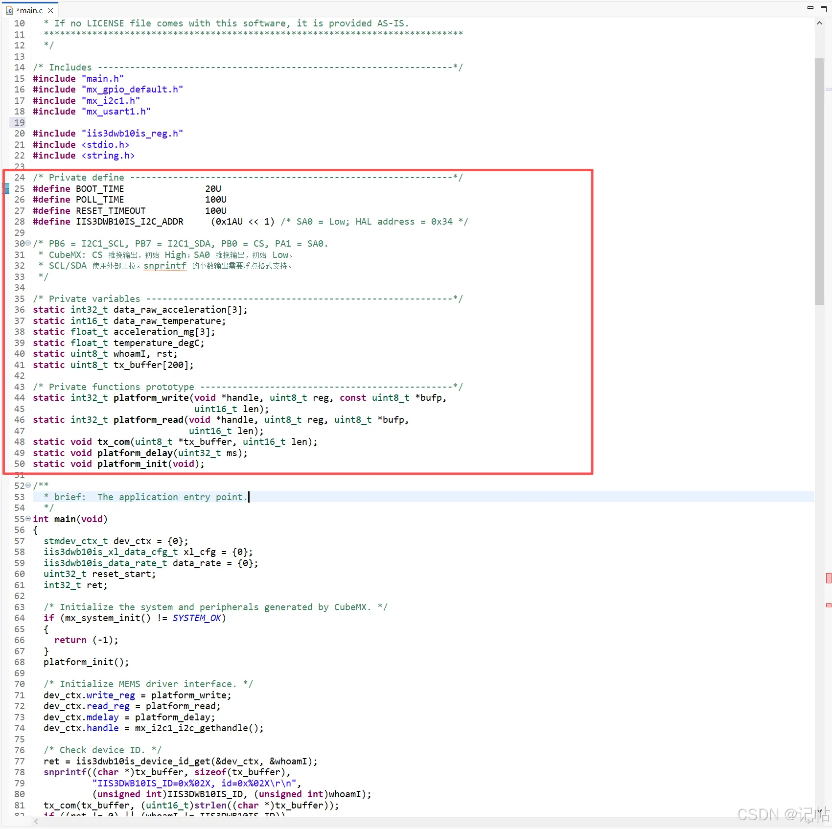
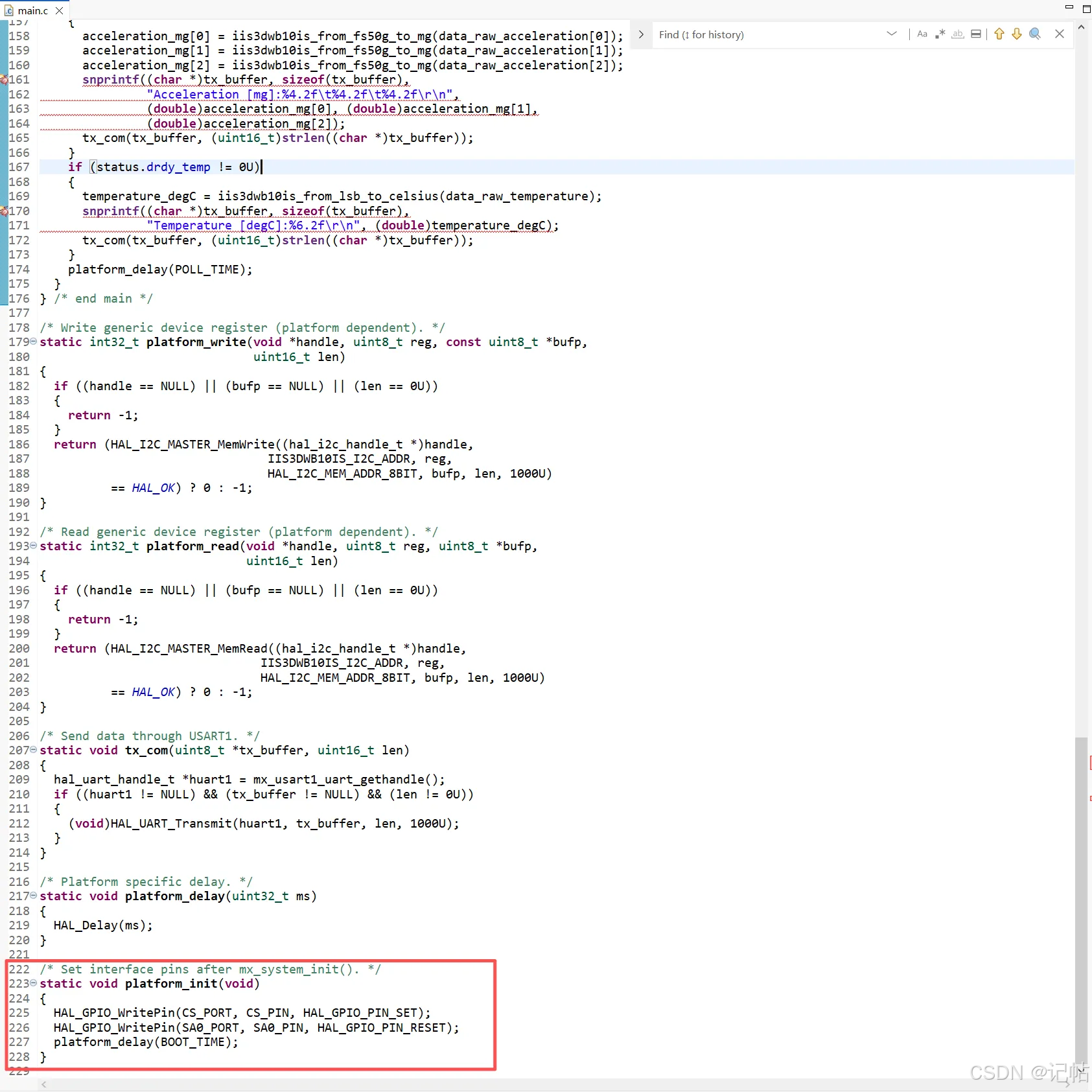
设置 CS、SA0 和器件地址
系统初始化完成后,调用 platform_init(),将 CS 置高、SA0 置低,再等待 20 ms。
c
/* Set interface pins after mx_system_init(). */
static void platform_init(void)
{
  HAL_GPIO_WritePin(CS_PORT, CS_PIN, HAL_GPIO_PIN_SET);
  HAL_GPIO_WritePin(SA0_PORT, SA0_PIN, HAL_GPIO_PIN_RESET);
  platform_delay(BOOT_TIME);
}
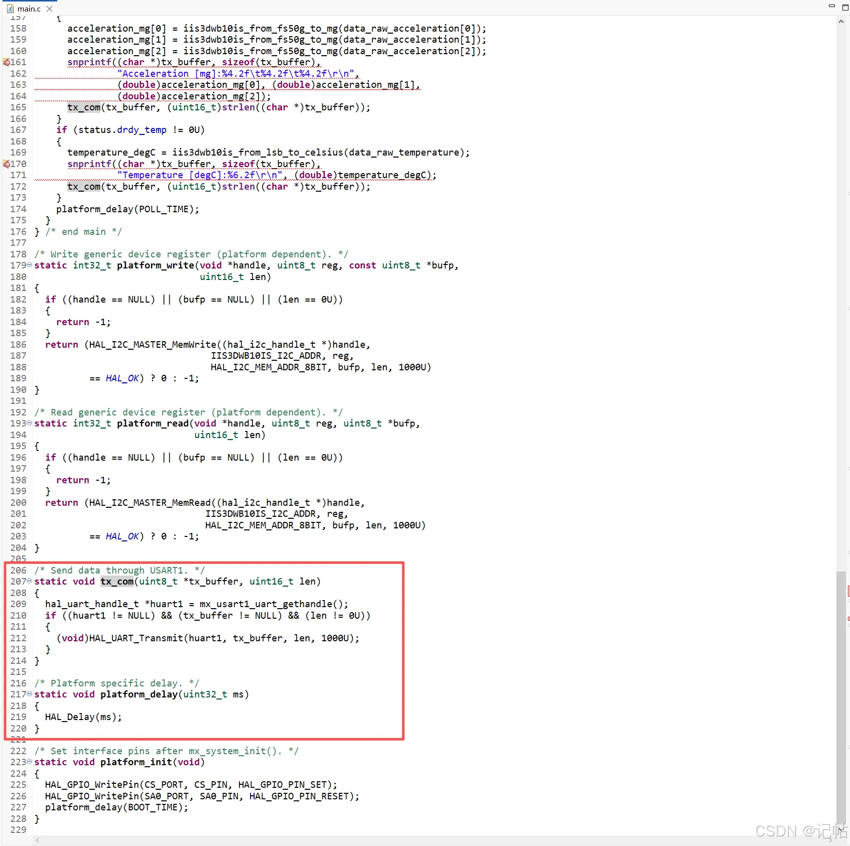
串口发送与延时
程序先通过 snprintf() 生成文本,再调用 tx_com() 发送。platform_delay() 直接调用 HAL 的毫秒延时接口。
c
/* Send data through USART1. */
static void tx_com(uint8_t *tx_buffer, uint16_t len)
{
  hal_uart_handle_t *huart1 = mx_usart1_uart_gethandle();
  if ((huart1 != NULL) && (tx_buffer != NULL) && (len != 0U))
  {
    (void)HAL_UART_Transmit(huart1, tx_buffer, len, 1000U);
  }
}

/* Platform specific delay. */
static void platform_delay(uint32_t ms)
{
  HAL_Delay(ms);
}
绑定驱动接口
在 main() 中,将 IIC 读写、延时函数及 I2C1 句柄绑定到驱动上下文。接着调用 iis3dwb10is_device_id_get() 读取芯片 ID。正常应得到 0x50;读取失败或 ID 不匹配时,程序返回错误,不进入采集循环。
芯片识别成功后,程序执行软件复位,并轮询 CTRL3 的复位位是否清零。复位状态检查设置了 100 ms 的超时阈值,避免持续等待。
c
  /* Initialize MEMS driver interface. */
  dev_ctx.write_reg = platform_write;
  dev_ctx.read_reg = platform_read;
  dev_ctx.mdelay = platform_delay;
  dev_ctx.handle = mx_i2c1_i2c_gethandle();

  /* Check device ID. */
  ret = iis3dwb10is_device_id_get(&dev_ctx, &whoamI);
  snprintf((char *)tx_buffer, sizeof(tx_buffer),
           "IIS3DWB10IS_ID=0x%02X, id=0x%02X\r\n",
           (unsigned int)IIS3DWB10IS_ID, (unsigned int)whoamI);
  tx_com(tx_buffer, (uint16_t)strlen((char *)tx_buffer));
  if ((ret != 0) || (whoamI != IIS3DWB10IS_ID))
  {
    return (-1);
  }

  /* Restore default configuration and wait for reset completion. */
  ret = iis3dwb10is_sw_reset(&dev_ctx);
  reset_start = HAL_GetTick();
  while (ret == 0)
  {
    ret = iis3dwb10is_read_reg(&dev_ctx, IIS3DWB10IS_CTRL3, &rst, 1U);
    if ((ret != 0) || ((rst & 0x01U) == 0U))
    {
      break;
    }
    if ((uint32_t)(HAL_GetTick() - reset_start) >= RESET_TIMEOUT)
    {
      ret = -1;
      break;
    }
    platform_delay(1U);
  }
  platform_delay(BOOT_TIME);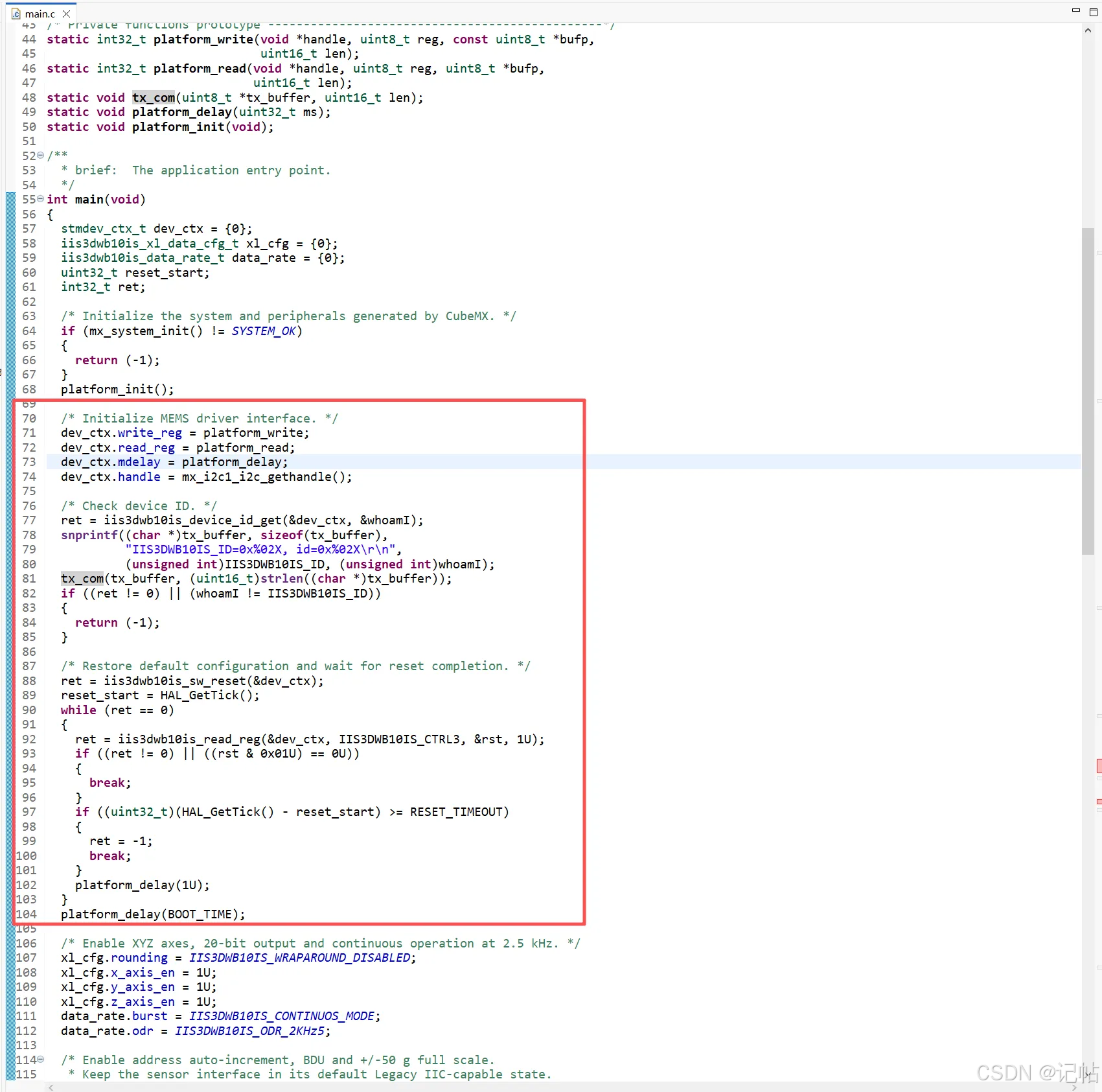
配置量程和输出数据率
本例将 IIS3DWB10IS 的加速度量程设置为 ±50 g,输出数据率(ODR)设置为 2.5 kHz,采用连续工作模式,并使能 X、Y、Z 三个轴。加速度数据采用 20 位有符号格式,每轴读取 4 字节。同时,使能 BDU(块数据更新)和 IF_INC(寄存器地址自动递增),以保持多字节数据读取的一致性,并支持连续读取多个寄存器。
c
  /* Enable XYZ axes, 20-bit output and continuous operation at 2.5 kHz. */
  xl_cfg.rounding = IIS3DWB10IS_WRAPAROUND_DISABLED;
  xl_cfg.x_axis_en = 1U;
  xl_cfg.y_axis_en = 1U;
  xl_cfg.z_axis_en = 1U;
  data_rate.burst = IIS3DWB10IS_CONTINUOS_MODE;
  data_rate.odr = IIS3DWB10IS_ODR_2KHz5;

  /* Enable address auto-increment, BDU and +/-50 g full scale.
   * Keep the sensor interface in its default Legacy IIC-capable state.
   */
  rst |= 0x04U; /* CTRL3.IF_INC */
  if ((ret != 0) ||
      (iis3dwb10is_write_reg(&dev_ctx, IIS3DWB10IS_CTRL3, &rst, 1U) != 0) ||
      (iis3dwb10is_block_data_update_set(&dev_ctx, PROPERTY_ENABLE) != 0) ||
      (iis3dwb10is_xl_full_scale_set(&dev_ctx, IIS3DWB10IS_50g) != 0) ||
      (iis3dwb10is_xl_data_config_set(&dev_ctx, xl_cfg) != 0) ||
      (iis3dwb10is_xl_data_rate_set(&dev_ctx, data_rate) != 0))
  {
    snprintf((char *)tx_buffer, sizeof(tx_buffer),
             "IIS3DWB10IS initialization error\r\n");
    tx_com(tx_buffer, (uint16_t)strlen((char *)tx_buffer));
    return (-1);
  }
  platform_delay(BOOT_TIME);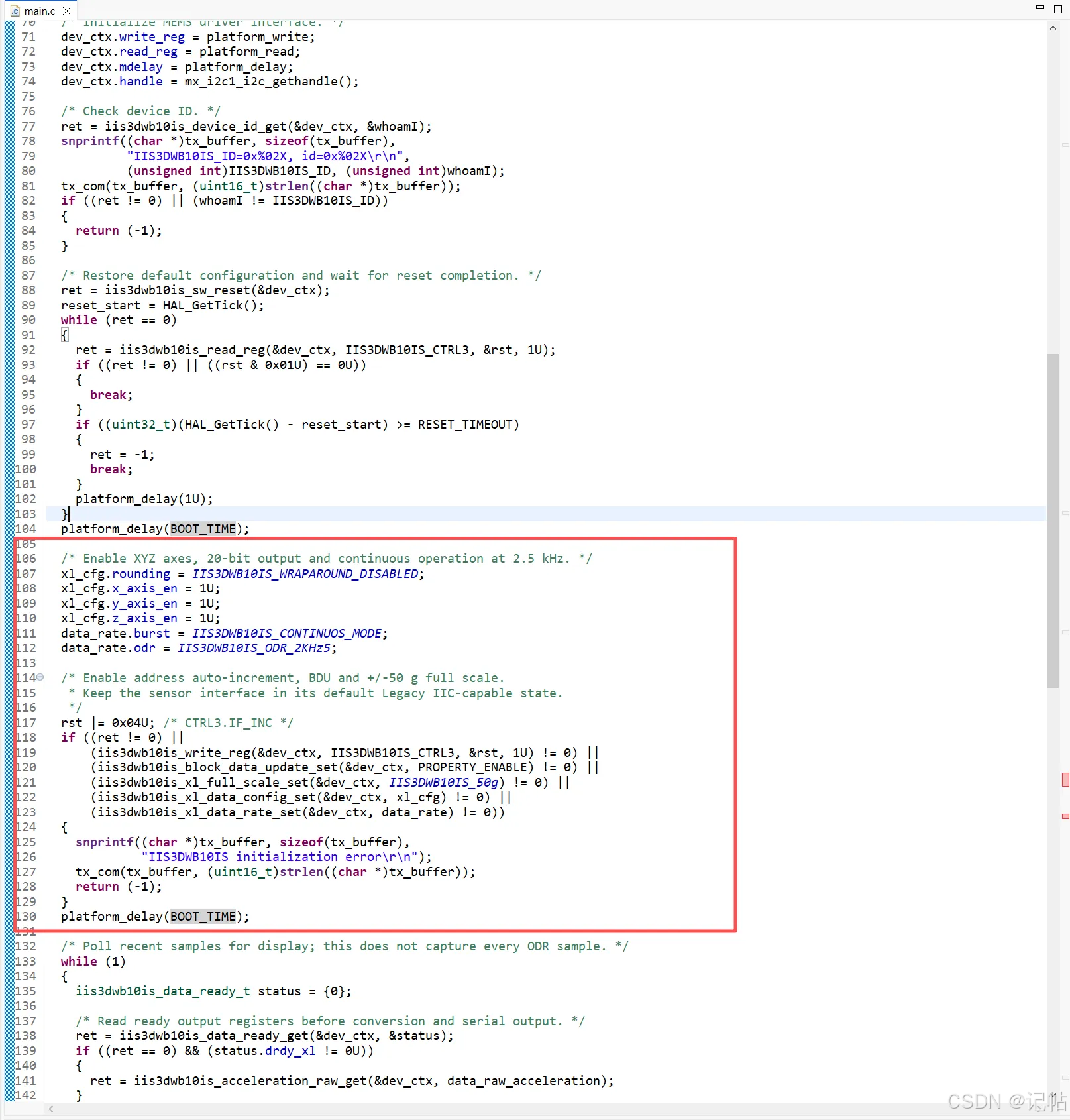
读取并显示数据
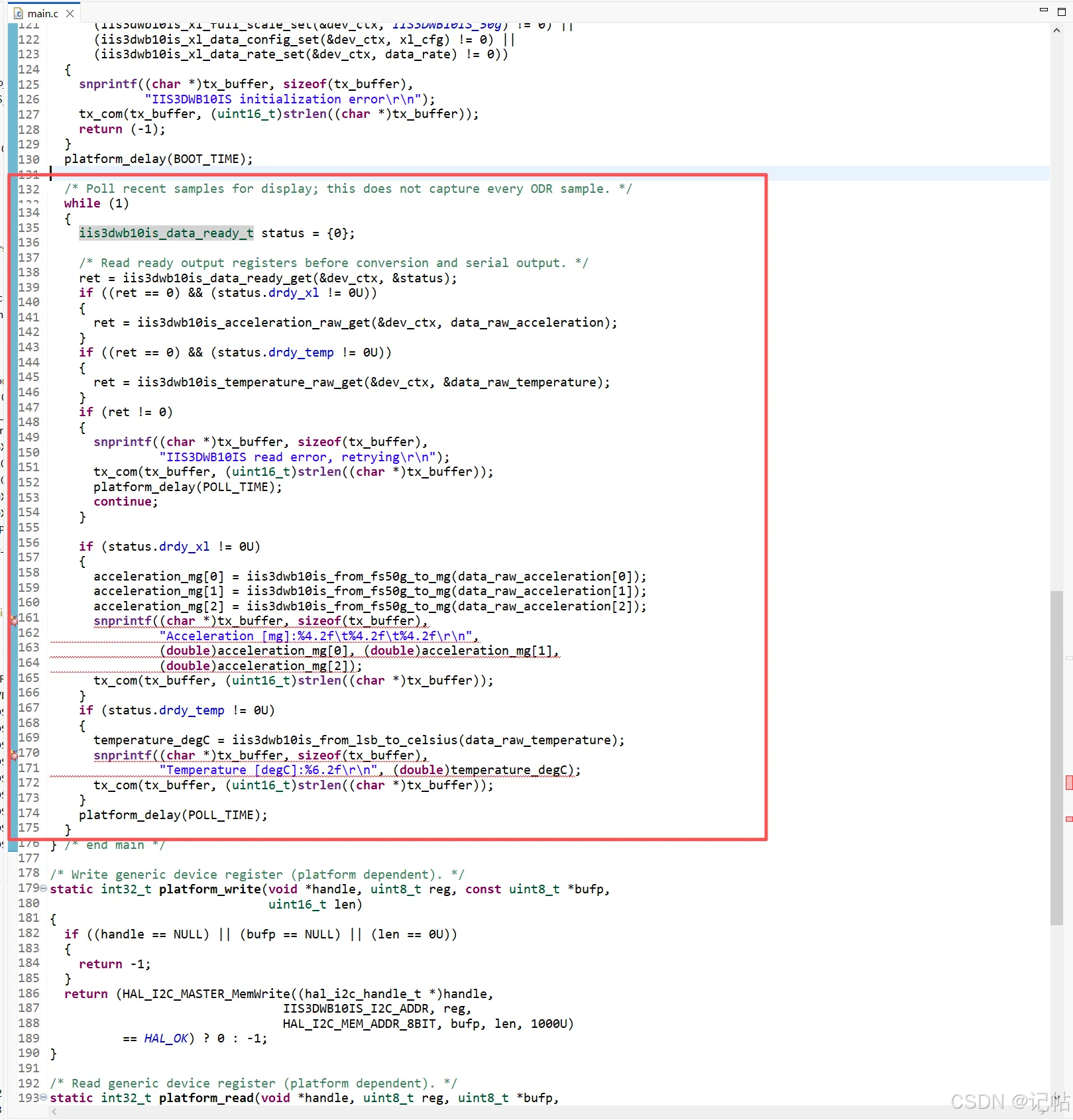
主循环先检查数据就绪状态,再读取加速度和温度。读操作成功后,才进行单位换算与串口输出;失败时提示错误,等待 100 ms 后重新读取。
c
  while (1)
  {
    iis3dwb10is_data_ready_t status = {0};

    /* Read ready output registers before conversion and serial output. */
    ret = iis3dwb10is_data_ready_get(&dev_ctx, &status);
    if ((ret == 0) && (status.drdy_xl != 0U))
    {
      ret = iis3dwb10is_acceleration_raw_get(&dev_ctx, data_raw_acceleration);
    }
    if ((ret == 0) && (status.drdy_temp != 0U))
    {
      ret = iis3dwb10is_temperature_raw_get(&dev_ctx, &data_raw_temperature);
    }
    if (ret != 0)
    {
      snprintf((char *)tx_buffer, sizeof(tx_buffer),
               "IIS3DWB10IS read error, retrying\r\n");
      tx_com(tx_buffer, (uint16_t)strlen((char *)tx_buffer));
      platform_delay(POLL_TIME);
      continue;
    }

    if (status.drdy_xl != 0U)
    {
      acceleration_mg[0] = iis3dwb10is_from_fs50g_to_mg(data_raw_acceleration[0]);
      acceleration_mg[1] = iis3dwb10is_from_fs50g_to_mg(data_raw_acceleration[1]);
      acceleration_mg[2] = iis3dwb10is_from_fs50g_to_mg(data_raw_acceleration[2]);
      snprintf((char *)tx_buffer, sizeof(tx_buffer),
               "Acceleration [mg]:%4.2f\t%4.2f\t%4.2f\r\n",
               (double)acceleration_mg[0], (double)acceleration_mg[1],
               (double)acceleration_mg[2]);
      tx_com(tx_buffer, (uint16_t)strlen((char *)tx_buffer));
    }
    if (status.drdy_temp != 0U)
    {
      temperature_degC = iis3dwb10is_from_lsb_to_celsius(data_raw_temperature);
      snprintf((char *)tx_buffer, sizeof(tx_buffer),
               "Temperature [degC]:%6.2f\r\n", (double)temperature_degC);
      tx_com(tx_buffer, (uint16_t)strlen((char *)tx_buffer));
    }
    platform_delay(POLL_TIME);
  }
运行效果
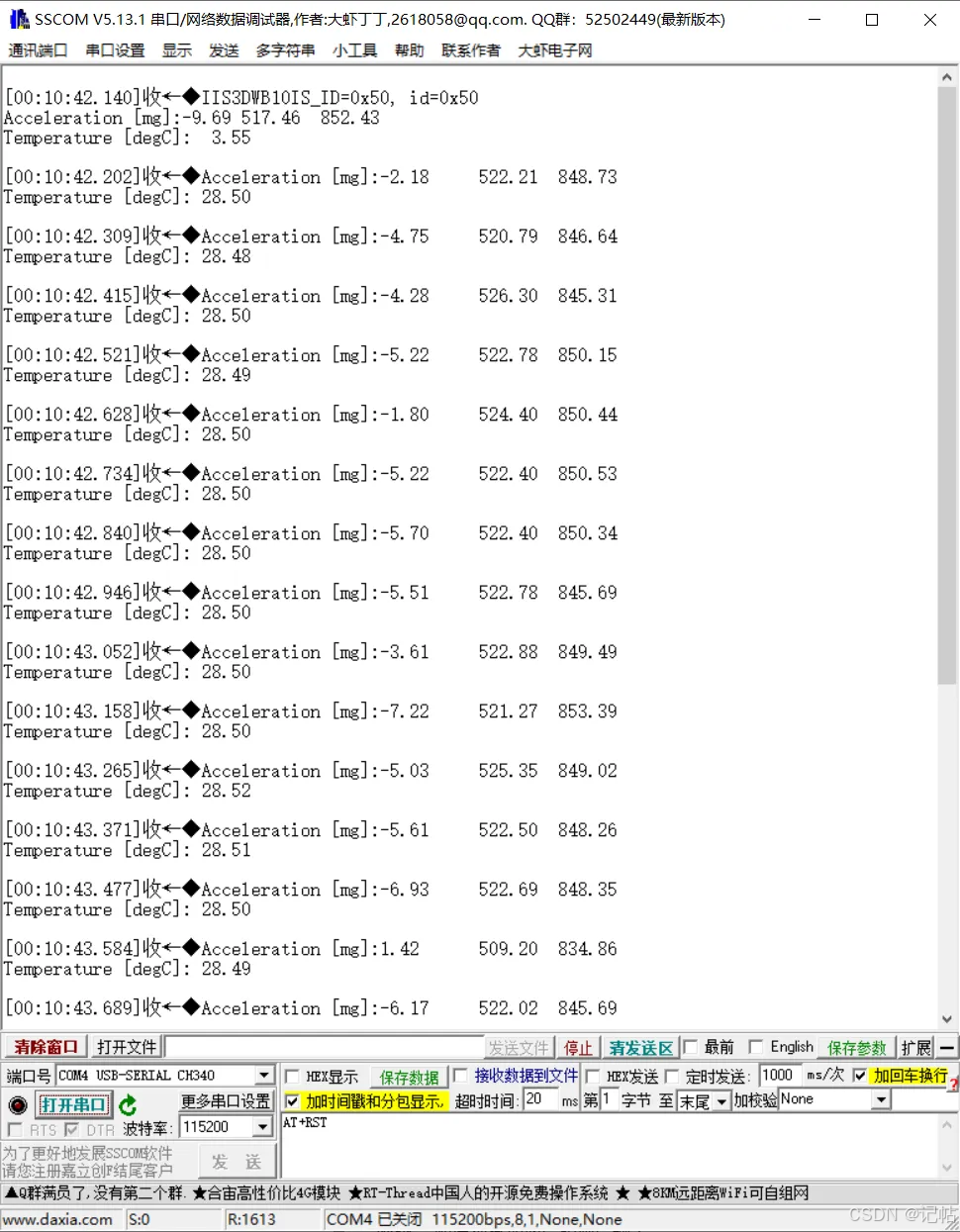
编译、下载程序后,打开串口调试助手并复位开发板。首先检查 ID 是否为 0x50,随后观察加速度和温度输出。