1. ASPM概述
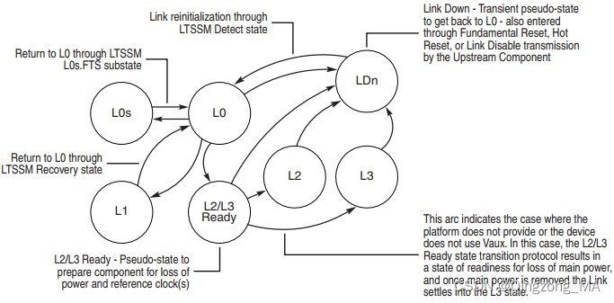
PCIe总线的电源管理包含ASPM(Active State Power Management)和软件电源管理两方面内容。所谓的ASPM是指PCIe链路在没有系统软件参与的情况下,由PCIe链路自发进行的电源管理方式。如下是PCIe的ASPM的状态机,其L1是强制性的规定,而L0s是可选的。
2. Debugging
2.1 如何查看ASPM的状态
对于Linux系统来说,可以使用"lspci -vvv"指令来查看ASPM的状态。
2.1.1 When ASPM is enabled
如下是一个PCIe ASPM使能的示例,请参考:
05:00.0 Network controller: Atheros Communications Inc. AR928X Wireless Network Adapter (PCI-Express) (rev 01)
        Subsystem: Atheros Communications Inc. Device 3099
        Control: I/O+ Mem+ BusMaster+ SpecCycle- MemWINV- VGASnoop- ParErr- Stepping- SERR+ FastB2B- DisINTx-
        Status: Cap+ 66MHz- UDF- FastB2B- ParErr- DEVSEL=fast >TAbort- <TAbort- <MAbort- >SERR- <PERR- INTx-
        Latency: 0, Cache Line Size: 64 bytes
        Interrupt: pin A routed to IRQ 19
        Region 0: Memory at dbdf0000 (64-bit, non-prefetchable) [size=64K]
        Capabilities: [40] Power Management version 2
                Flags: PMEClk- DSI- D1+ D2- AuxCurrent=375mA PME(D0+,D1+,D2-,D3hot+,D3cold-)
                Status: D0 NoSoftRst- PME-Enable- DSel=0 DScale=0 PME-
        Capabilities: [50] MSI: Enable- Count=1/1 Maskable- 64bit-
                Address: 00000000  Data: 0000
        Capabilities: [60] Express (v1) Legacy Endpoint, MSI 00
                DevCap: MaxPayload 128 bytes, PhantFunc 0, Latency L0s <512ns, L1 <64us
                        ExtTag- AttnBtn- AttnInd- PwrInd- RBE- FLReset-
                DevCtl: Report errors: Correctable- Non-Fatal- Fatal- Unsupported-
                        RlxdOrd+ ExtTag- PhantFunc- AuxPwr- NoSnoop-
                        MaxPayload 128 bytes, MaxReadReq 512 bytes
                DevSta: CorrErr- UncorrErr+ FatalErr- UnsuppReq+ AuxPwr- TransPend-
                LnkCap: Port #0, Speed 2.5GT/s, Width x1, ASPM unknown, Latency L0 <512ns, L1 <64us
                        ClockPM- Surprise- LLActRep- BwNot-
                LnkCtl: ASPM L1 Enabled; RCB 128 bytes Disabled- Retrain- CommClk+
                        ExtSynch- ClockPM- AutWidDis- BWInt- AutBWInt-
                LnkSta: Speed 2.5GT/s, Width x1, TrErr- Train- SlotClk+ DLActive- BWMgmt- ABWMgmt-
        Capabilities: [90] MSI-X: Enable- Count=1 Masked-
                Vector table: BAR=0 offset=00000000
                PBA: BAR=0 offset=00000000
        Capabilities: [100] Advanced Error Reporting
                UESta:  DLP- SDES- TLP- FCP- CmpltTO- CmpltAbrt- UnxCmplt- RxOF- MalfTLP- ECRC- UnsupReq+ ACSViol-
                UEMsk:  DLP- SDES- TLP- FCP- CmpltTO- CmpltAbrt- UnxCmplt- RxOF- MalfTLP- ECRC- UnsupReq- ACSViol-
                UESvrt: DLP+ SDES- TLP- FCP+ CmpltTO- CmpltAbrt- UnxCmplt- RxOF+ MalfTLP+ ECRC- UnsupReq- ACSViol-
                CESta:  RxErr- BadTLP- BadDLLP- Rollover- Timeout- NonFatalErr-
                CEMsk:  RxErr- BadTLP- BadDLLP- Rollover- Timeout- NonFatalErr-
                AERCap: First Error Pointer: 14, GenCap+ CGenEn- ChkCap+ ChkEn-
        Capabilities: [140] Virtual Channel <?>
        Capabilities: [160] Device Serial Number 00-00-00-00-00-00-00-00
        Kernel driver in use: ath9k
        Kernel modules: ath9k
2.1.2 When ASPM is disabled
如下是一个PCIe ASPM没有使能的示例,请参考:
localhost ~ # lspci -vvvv -s 03:00
03:00.0 Network controller: Atheros Communications Inc. AR928X Wireless Network Adapter (PCI-Express) (rev 01)
        Subsystem: Atheros Communications Inc. Device 309a
        Control: I/O+ Mem+ BusMaster+ SpecCycle- MemWINV- VGASnoop- ParErr- Stepping- SERR- FastB2B- DisINTx-
        Status: Cap+ 66MHz- UDF- FastB2B- ParErr- DEVSEL=fast >TAbort- <TAbort- <MAbort- >SERR- <PERR- INTx-
        Latency: 0, Cache Line Size: 64 bytes
        Interrupt: pin A routed to IRQ 17
        Region 0: Memory at f0100000 (64-bit, non-prefetchable) [size=64K]
        Capabilities: [40] Power Management version 2
                Flags: PMEClk- DSI- D1+ D2- AuxCurrent=375mA PME(D0+,D1+,D2-,D3hot+,D3cold-)
                Status: D0 NoSoftRst- PME-Enable- DSel=0 DScale=0 PME-
        Capabilities: [50] MSI: Enable- Count=1/1 Maskable- 64bit-
                Address: 00000000  Data: 0000
        Capabilities: [60] Express (v1) Legacy Endpoint, MSI 00
                DevCap: MaxPayload 128 bytes, PhantFunc 0, Latency L0s <512ns, L1 <64us
                        ExtTag- AttnBtn- AttnInd- PwrInd- RBE- FLReset-
                DevCtl: Report errors: Correctable- Non-Fatal- Fatal- Unsupported-
                        RlxdOrd+ ExtTag- PhantFunc- AuxPwr- NoSnoop-
                        MaxPayload 128 bytes, MaxReadReq 512 bytes
                DevSta: CorrErr- UncorrErr+ FatalErr- UnsuppReq+ AuxPwr- TransPend-
                LnkCap: Port #0, Speed 2.5GT/s, Width x1, ASPM unknown, Latency L0 <512ns, L1 <64us
                        ClockPM- Surprise- LLActRep- BwNot-
                LnkCtl: ASPM Disabled; RCB 128 bytes Disabled- Retrain- CommClk+
                        ExtSynch- ClockPM- AutWidDis- BWInt- AutBWInt-
                LnkSta: Speed 2.5GT/s, Width x1, TrErr- Train- SlotClk+ DLActive- BWMgmt- ABWMgmt-
        Capabilities: [90] MSI-X: Enable- Count=1 Masked-
                Vector table: BAR=0 offset=00000000
                PBA: BAR=0 offset=00000000
        Capabilities: [100] Advanced Error Reporting
                UESta:  DLP- SDES- TLP- FCP- CmpltTO- CmpltAbrt- UnxCmplt- RxOF- MalfTLP- ECRC- UnsupReq+ ACSViol-
                UEMsk:  DLP- SDES- TLP- FCP- CmpltTO- CmpltAbrt- UnxCmplt- RxOF- MalfTLP- ECRC- UnsupReq- ACSViol-
                UESvrt: DLP+ SDES- TLP- FCP+ CmpltTO- CmpltAbrt- UnxCmplt- RxOF+ MalfTLP+ ECRC- UnsupReq- ACSViol-
                CESta:  RxErr- BadTLP- BadDLLP- Rollover- Timeout- NonFatalErr-
                CEMsk:  RxErr- BadTLP- BadDLLP- Rollover- Timeout- NonFatalErr-
                AERCap: First Error Pointer: 14, GenCap+ CGenEn- ChkCap+ ChkEn-
        Capabilities: [140] Virtual Channel <?>
        Capabilities: [160] Device Serial Number 00-00-00-00-00-00-00-00
        Kernel driver in use: ath9k
        Kernel modules: ath9k
2.1.3 为什么我的设备ASPM没有使能?
ASPM应该由RC和所有EP自动协商。如果你的设备查询之后,发现禁用了ASPM,可能有以下原因:
- BIOS没有使能ASPM的相关设置
- L0s是可选的,可能你得设备只支持L1
- BIOS可能发生了相关未知的问题
- ASPM不仅需要EP的支持,也需要RC的支持
2.2 如何使能ASPM
当前我们大多数的Wi-Fi芯片所使用的接口都是PCIe,而且大多数都是手持设备,所以这时候对于设备的功耗就有很大的要求。所以也就需要支持ASPM的L0s状态,以达到最佳的功耗状态。
2.2.1 如何在Kernel中使能ASPM
操作系统一般不干涉ASPM,但是我们可以通过Kernel来调试PCIe RC/EP的ASPM设置。所以Kernel一般需要使能CONFIG_PCIEASPM配置,以此达到能够调试的目的:
config PCIEASPM
        bool "PCI Express ASPM support(Experimental)"
        depends on PCI && EXPERIMENTAL && PCIEPORTBUS
        default n
        help
          This enables PCI Express ASPM (Active State Power Management) and
          Clock Power Management. ASPM supports state L0/L0s/L1.

          When in doubt, say N.
2.2.1.1 强制ASPM的状态
也可以通过boot的参数,强制enable/disable ASPM:
        pcie_aspm=      [PCIE] Forcibly enable or disable PCIe Active State Power
                        Management.
                off     Disable ASPM.
                force   Enable ASPM even on devices that claim not to support it.
                        WARNING: Forcing ASPM on may cause system lockups.
2.2.2 使用enable_aspm使能ASPM
enable_aspm是一个脚本,可以用于启用ASPM。具体你可以阅读如下链接:
只需要修改如下三个参数:
ROOT_COMPLEX="00:1c.1"
ENDPOINT="03:00.0"

# We'll only enable the last 2 bits by using a mask
# of :3 to setpci, this will ensure we keep the existing
# values on the byte.
#
# Hex  Binary  Meaning
# -------------------------
# 0    0b00    L0 only
# 1    0b01    L0s only
# 2    0b10    L1 only
# 3    0b11    L1 and L0s
ASPM_SETTING=3
2.2.3 使用setpci使能ASPM
"PCIE Link Control Register"可以通过"lspci -vvv"进行读取,所以可以通过"setpci"工具修改相关寄存器,来使能PCIe ASPM。
2.2.3.1 如何读取"Link Control Register"?
如下是"Link Control Register"中关于ASPM的状态展示:
0b00 = L0 only
0b01 = L0s only
0b10 = L1 only
0b11 = L1 and L0s
2.2.3.2 如何找到"Link Control Register"?
首先查找你想要的设备,如下所示:
user@tux ~ $ lspci | grep -i atheros
03:00.0 Network controller: Atheros Communications Inc. Device 0030 (rev 01)
03:00.0是总线地址。现在,使用"lspci -t"检查该设备位于哪个RC上。
-[0000:00]-+-00.0
           +-02.0
           +-02.1
           +-03.0
           +-03.2
           +-03.3
           +-19.0
           +-1a.0
           +-1a.1
           +-1a.7
           +-1b.0
           +-1c.0-[0000:02]--
           +-1c.1-[0000:03]----00.0
           +-1c.2-[0000:04]--
           +-1c.3-[0000:05-0c]--
           +-1c.4-[0000:0d-14]--
           +-1d.0
           +-1d.1
           +-1d.2
           +-1d.7
           +-1e.0-[0000:15-18]--+-00.0
           |                    \-00.1
           +-1f.0
           +-1f.1
           +-1f.2
           \-1f.3
在这种情况下,我们看到03:00.0位于00:1c.1上,你可以执行"lspci -s 00:1c.1 -xxx",以获取该设备的PCI配置空间。PCIe规范有一个有趣的小算法,可以从PCI配置空间中找到链路控制寄存器。逻辑如下:
-
Read 0x34 and read the register that points to
-
If that value is not 0x10 then read the next byte (0x35) and go read that register
-
If that register is not 0x10 then read the next byte and go read that register
-
Repeat this until you find a register that has 0x10
-
Once you find the register with 0x10 then add 0x10 to the final register you were reading
-
The Link Control Register is this final register + 0x10 Lets analyze a real world example of a root complex, specifically the one of the root complex above.
user@tux ~ $ sudo lspci -s 00:1c.1 -xxx
00:1c.1 PCI bridge: Intel Corporation 82801H (ICH8 Family) PCI Express Port 2 (rev 03)
00: 86 80 41 28 07 05 10 00 03 00 04 06 10 00 81 00
10: 00 00 00 00 00 00 00 00 00 03 03 00 30 30 00 00
20: 00 dc 30 df e1 df e1 df 00 00 00 00 00 00 00 00
30: 00 00 00 00 40 00 00 00 00 00 00 00 0b 02 04 00
40: 10 80 41 01 c0 8f 00 00 00 00 10 00 11 2c 11 02
50: 40 00 11 30 e0 a0 18 00 00 00 48 01 00 00 00 00
60: 00 00 00 00 00 00 00 00 00 00 00 00 00 00 00 00
70: 00 00 00 00 00 00 00 00 00 00 00 00 00 00 00 00
80: 05 90 01 00 0c 30 e0 fe 69 41 00 00 00 00 00 00
90: 0d a0 00 00 aa 17 ad 20 00 00 00 00 00 00 00 00
a0: 01 00 02 c8 00 00 00 00 00 00 00 00 00 00 00 00
b0: 00 00 00 00 00 00 00 00 00 00 00 00 00 00 00 00
c0: 00 00 00 00 00 00 00 00 00 00 00 00 00 00 00 00
d0: 00 00 00 00 00 00 00 00 80 00 11 08 00 00 00 00
e0: 00 0f c7 00 06 07 08 00 33 00 00 00 00 00 00 00
f0: 00 00 00 00 00 00 00 00 86 0f 05 00 00 00 00 00
首先读取地址0x34,我们看到它是0x40(在这里不要跳到下一个字节)。我们读取0x40,并看到它是0x10。现在我们加上0x40 + 0x10 = 0x50。我们读取0x50。0x50是链路控制寄存器的值。0x50的值是0x40。这意味着只有L0被启用,因此ASPM完全被禁用。要调整此RC的ASPM,我们需要首先保留原始值,然后与我们的新ASPM设置进行OR运算。
注意:事实证明,0x50也用于ICH6、ICH7、ICH8、ICH9的链路控制寄存器。
# Disables ASPM, enables only L0 (this was the existing setting)
sudo setpci -s 00:1c.1 0x50.B=0x40

# Enable L0s only
sudo setpci -s 00:1c.1 0x50.B=0x41

# Enable L1 only
sudo setpci -s 00:1c.1 0x50.B=0x42

# Enable L1 and L0s
sudo setpci -s 00:1c.1 0x50.B=0x43
现在,让我们可以调整你的设备。获取到的设备的PCIe配置空间如下所示:
user@tux ~ $ sudo lspci -s 03:00.0 -xxx
03:00.0 Network controller: Atheros Communications Inc. Device 0030 (rev 01)
00: 8c 16 30 00 03 01 10 40 01 00 80 02 10 00 00 00
10: 04 00 3e df 00 00 00 00 00 00 00 00 00 00 00 00
20: 00 00 00 00 00 00 00 00 00 00 00 00 8c 16 16 31
30: 00 00 00 00 40 00 00 00 00 00 00 00 0b 01 00 00
40: 01 50 c3 5b 00 00 00 00 00 00 00 00 00 00 00 00
50: 05 70 84 01 00 00 00 00 00 00 00 00 00 00 00 00
60: 00 00 00 00 00 00 00 00 00 00 00 00 00 00 00 00
70: 10 00 02 00 00 87 04 05 10 20 0b 00 11 5c 03 00
80: 41 00 11 10 00 00 00 00 00 00 00 00 00 00 00 00
90: 00 00 00 00 10 00 00 00 00 00 00 00 00 00 00 00
a0: 00 00 00 00 00 00 00 00 00 00 00 00 00 00 00 00
b0: 00 00 00 00 00 00 00 00 00 00 00 00 00 00 00 00
c0: 00 00 00 00 00 00 00 00 00 00 00 00 00 00 00 00
d0: 00 00 00 00 00 00 00 00 00 00 00 00 00 00 00 00
e0: 00 00 00 00 00 00 00 00 00 00 00 00 00 00 00 00
f0: 00 00 00 00 00 00 00 00 00 00 00 00 00 00 00 00
这个例子稍微复杂一些,所以我们将逐行进行分析:
00: 8c 16 30 00 03 01 10 40 01 00 80 02 10 00 00 00
10: 04 00 3e df 00 00 00 00 00 00 00 00 00 00 00 00
20: 00 00 00 00 00 00 00 00 00 00 00 00 8c 16 16 31
30: 00 00 00 00 40 00 00 00 00 00 00 00 0b 01 00 00
    ^            ^
    |            |
   0x30         0x34

So 0x34 = 0x40. 0x40 is not 0x10 so we go read 0x40 now

40: 01 50 c3 5b 00 00 00 00 00 00 00 00 00 00 00 00
    ^
    |
   0x40 = 0x01, this is not 0x10 so read the next byte

40: 01 50 c3 5b 00 00 00 00 00 00 00 00 00 00 00 00
       ^
       |
      0x41 = 0x50, so go read that register next

50: 05 70 84 01 00 00 00 00 00 00 00 00 00 00 00 00
    ^
    |
   0x50 = 0x05, this is not 0x10, so go read the next byte.
   The next byte 0x51 = 0x70 so we go read that register next.

70: 10 00 02 00 00 87 04 05 10 20 0b 00 11 5c 03 00
    ^
    |
    At last, 0x70 = 0x10. So now we do 0x70 + 0x10 = 0x80 and go read 0x80.

80: 41 00 11 10 00 00 00 00 00 00 00 00 00 00 00 00
    ^
    |
    0x80 = 0x41
    0x41 = 0b1000001 so this has ASPM L0s on only.
所以,使用如下指令修改PCIe ASPM的状态:
# Disables ASPM, enables only L0
sudo setpci -s 03:00.0 0x80.B=0x40

# Enable L0s only (this was the existing setting)
sudo setpci -s 03:00.0 0x80.B=0x41

# Enable L1 only
sudo setpci -s 03:00.0 0x80.B=0x42

# Enable L1 and L0s
sudo setpci -s 03:00.0 0x80.B=0x43