这篇文章介绍arduino使用和安装arduino_bridge
将arduino与树莓派连接
查看arduino的端口号,我们这里查看到的时ttyUSB0
bash
ll /dev/ttyUSB*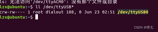
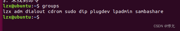
将当前用户添加进dialout组
bash
sudo usermod -a -G dialout your_user_name然后重启树莓派,然后才能生效
然后如果你可以在列出的组中找到dialout,这就说明你已经加入到dialout中了
group
安装arduino
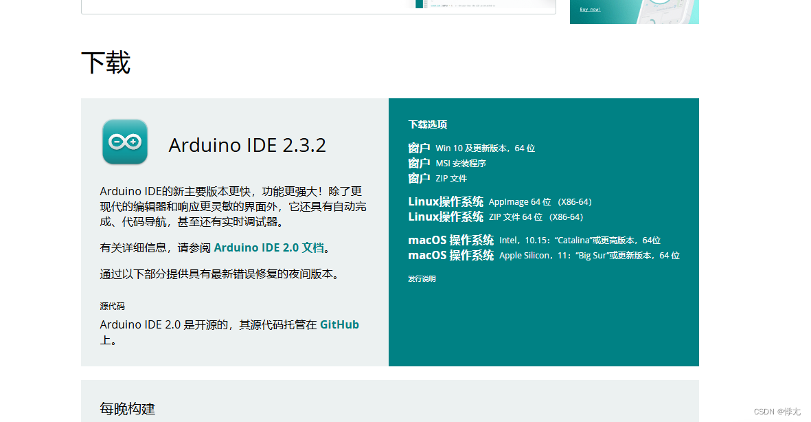
1.下载arduino ide安装包
官方下载链接:https://www.arduino.cc/en/Main/Software
2.使用tar命令对压缩包解压
bash
tar -xvf arduino-1.x.y-linux64.tar.xz3.将解压后的文件移动到/opt下
bash
sudo mv arduino-1.x.y /opt4.进入安装目录,对install.sh添加可执行权限,并执行安装
bash
cd /opt/arduino-1.x.y
sudo chmod +x install.sh
sudo ./install.sh
5.启动并配置 Arduino IDE
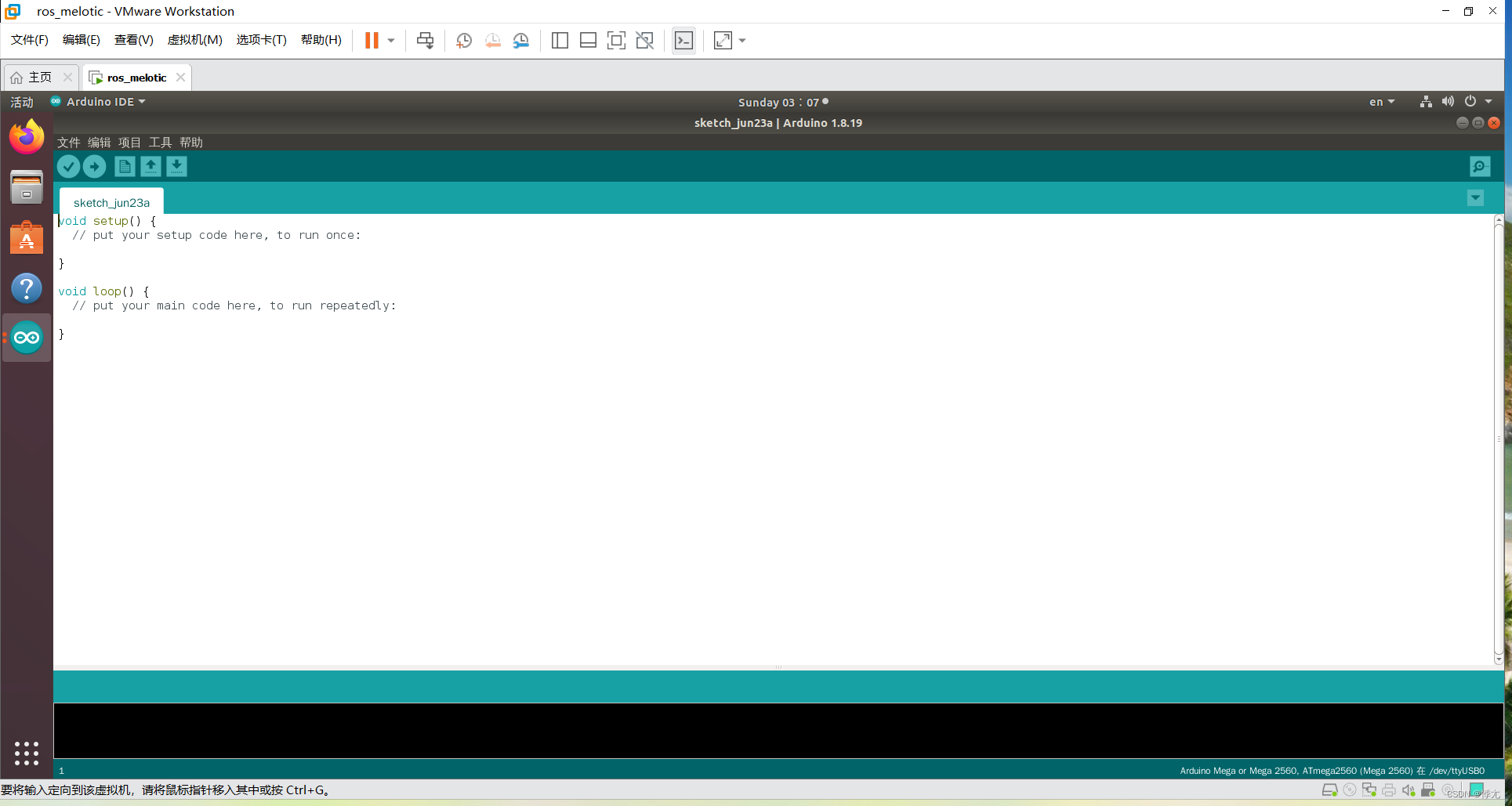
在命令行直接输入:arduino,或者点击左下的显示应用程序搜索 arduino IDE。启动如下:
cpp
// 初始化函数
void setup() {
  //将LED灯引脚(引脚值为13,被封装为了LED_BUTLIN)设置为输出模式
  pinMode(LED_BUILTIN, OUTPUT);
}

// 循环执行函数
void loop() {
  digitalWrite(LED_BUILTIN, HIGH);   // 打开LED灯
  delay(1000);                       // 休眠1000毫秒
  digitalWrite(LED_BUILTIN, LOW);    // 关闭LED灯
  delay(1000);                       // 休眠1000毫秒
}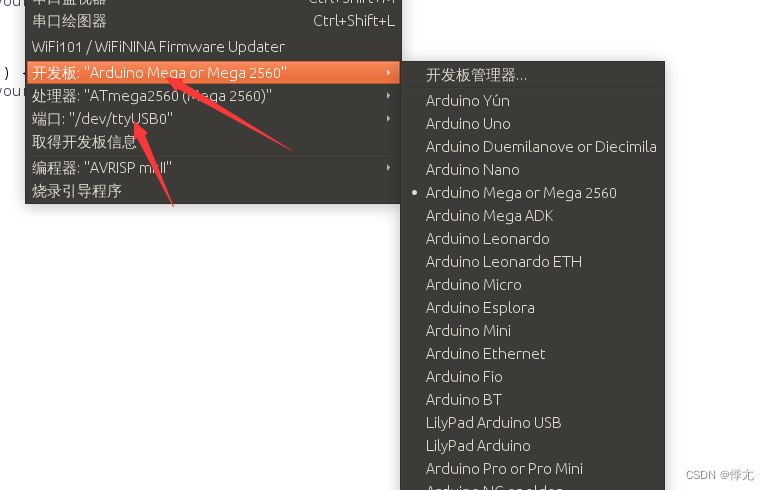
开发板选择Arduino mega,端口号选择/dev/ttyUSB0
上传该代码,观察arduino板载灯闪烁
到此arduino的安装就结束了
接下来安装ros_arduino_bridge
该功能包包含Arduino库和用来控制Arduino的ROS驱动包,它旨在成为在ROS下运行Arduino控制的机器人的完整解决方案。
其中当前主要关注的是:功能包集中一个兼容不同驱动的机器人的基本控制器(base controller),它可以接收ROS Twist类型的消息,可以发布里程计数据。上位机需要使用ROS(建议 melodic);
1.下载
新建ROS工作空间
bash
mkdir -p catkin_ws/src
cd catkin_ws
catkin_make
进入ROS工作空间的src目录,输入命令:
bash
cd catkin_ws/src
git clone https://github.com/hbrobotics/ros_arduino_bridge.git
2.ros_arduino_bridge 架构
文件结构说明在这里插入代码片 ├── ros_arduino_bridge # metapackage (元功能包)
│ ├── CMakeLists.txt
│ └── package.xml
├── ros_arduino_firmware #固件包,更新到Arduino
│ ├── CMakeLists.txt
│ ├── package.xml
│ └── src
│ └── libraries #库目录
│ ├── MegaRobogaiaPololu #针对Pololu电机控制器,MegaRobogaia编码器的头文件定义
│ │ ├── commands.h #定义命令头文件
│ │ ├── diff_controller.h #差分轮PID控制头文件
│ │ ├── MegaRobogaiaPololu.ino #PID实现文件
│ │ ├── sensors.h #传感器相关实现,超声波测距,Ping函数
│ │ └── servos.h #伺服器头文件
│ └── ROSArduinoBridge #Arduino相关库定义
│ ├── commands.h #定义命令
│ ├── diff_controller.h #差分轮PID控制头文件
│ ├── encoder_driver.h #编码器驱动头文件
│ ├── encoder_driver.ino #编码器驱动实现, 读取编码器数据,重置编码器等
│ ├── motor_driver.h #电机驱动头文件
│ ├── motor_driver.ino #电机驱动实现,初始化控制器,设置速度
│ ├── ROSArduinoBridge.ino #核心功能实现,程序入口
│ ├── sensors.h #传感器头文件及实现
│ ├── servos.h #伺服器头文件,定义插脚,类
│ └── servos.ino #伺服器实现
├── ros_arduino_msgs #消息定义包
│ ├── CMakeLists.txt
│ ├── msg #定义消息
│ │ ├── AnalogFloat.msg #定义模拟IO浮点消息
│ │ ├── Analog.msg #定义模拟IO数字消息
│ │ ├── ArduinoConstants.msg #定义常量消息
│ │ ├── Digital.msg #定义数字IO消息
│ │ └── SensorState.msg #定义传感器状态消息
│ ├── package.xml
│ └── srv #定义服务
│ ├── AnalogRead.srv #模拟IO输入
│ ├── AnalogWrite.srv #模拟IO输出
│ ├── DigitalRead.srv #数字IO输入
│ ├── DigitalSetDirection.srv #数字IO设置方向
│ ├── DigitalWrite.srv #数字IO输入
│ ├── ServoRead.srv #伺服电机输入
│ └── ServoWrite.srv #伺服电机输出
└── ros_arduino_python #ROS相关的Python包,用于上位机,树莓派等开发板或电脑等。
├── CMakeLists.txt
├── config #配置目录
│ └── arduino_params.yaml #定义相关参数,端口,rate,PID,sensors等默认参数。由arduino.launch调用
├── launch
│ └── arduino.launch #启动文件
├── nodes
│ └── arduino_node.py #python文件,实际处理节点,由arduino.launch调用,即可单独调用。
├── package.xml
├── setup.py
└── src #Python类包目录
└── ros_arduino_python
├── arduino_driver.py #Arduino驱动类
├── arduino_sensors.py #Arduino传感器类
├── base_controller.py #基本控制类,订阅cmd_vel话题,发布odom话题
└── init.py #类包默认空文件
上述目录结构虽然复杂,但是关注的只有两大部分:
ros_arduino_bridge/ros_arduino_firmware/src/libraries/ROSArduinoBridge
ros_arduino_bridge/ros_arduino_python/config/arduino_params.yaml
接下来我们对代码进行测试
1.串口命令
在主程序中,包含了 commands.h,该文件中包含了当前程序预定义的串口命令,可以编译程序并上传至 Arduino 电路板,然后打开串口监视器测试(当前程序并未修改,所以并非所有串口可用):
w 可以用于控制引脚电平
x 可以用于模拟输出
以LED灯控制为例,通过串口监视器录入命令:
w 13 0 == LED灯关闭
w 13 1 == LED灯打开
x 13 50 == LED灯PWM值为50
2.修改主程序入口,主要是添加
#define Tb6612_MOTOR_DRIVER
cpp
/*********************************************************************
 *  ROSArduinoBridge

   控制差速驱动机器人的Arduino程序,允许通过一组简单的串行命令来控制机器人,并接收传感器和里程数据。
   该程序默认配置假定使用Arduino Mega、Pololu电机控制器盾和Robogaia Mega编码器盾。
   如果使用不同的电机控制器或编码器方法,可以编辑readEncoder()和setMotorSpeed()包装函数。
 *********************************************************************/
//是否启用基座控制器
#define USE_BASE      // Enable the base controller code
//#undef USE_BASE     // Disable the base controller code

/* Define the motor controller and encoder library you are using */

启用基座控制器需要设置的电机驱动以及编码器驱
#ifdef USE_BASE
   /* The Pololu VNH5019 dual motor driver shield */
   //#define POLOLU_VNH5019

   /* The Pololu MC33926 dual motor driver shield */
   //#define POLOLU_MC33926

   /* The RoboGaia encoder shield */
   //#define ROBOGAIA

   /* Encoders directly attached to Arduino board */
   //#define ARDUINO_ENC_COUNTER
   //1.添加自定义编码器驱动
   #define ARDUINO_MY_COUNTER


   /* L298 Motor driver*/
   //#define L298_MOTOR_DRIVER
   #define Tb6612_MOTOR_DRIVER
#endif
//是否启用舵机
//#define USE_SERVOS  // Enable use of PWM servos as defined in servos.h
#undef USE_SERVOS     // Disable use of PWM servos


//波特率
/* Serial port baud rate */
#define BAUDRATE     57600
//最大PWM值
/* Maximum PWM signal */
#define MAX_PWM        255

#if defined(ARDUINO) && ARDUINO >= 100
#include "Arduino.h"
#else
#include "WProgram.h"
#endif

/* Include definition of serial commands */
#include "commands.h"

/* Sensor functions */
#include "sensors.h"

/* Include servo support if required */
#ifdef USE_SERVOS
   #include <Servo.h>
   #include "servos.h"
#endif


//
#ifdef USE_BASE
  /* Motor driver function definitions */
  #include "motor_driver.h"

  /* Encoder driver function definitions */
  #include "encoder_driver.h"

  /* PID parameters and functions */
  #include "diff_controller.h"

  /* Run the PID loop at 30 times per second */
  #define PID_RATE           30     // Hz

  /* Convert the rate into an interval */
  const int PID_INTERVAL = 1000 / PID_RATE;

  /* Track the next time we make a PID calculation */
  unsigned long nextPID = PID_INTERVAL;

  /* Stop the robot if it hasn't received a movement command
   in this number of milliseconds */
  #define AUTO_STOP_INTERVAL 2000
  long lastMotorCommand = AUTO_STOP_INTERVAL;
#endif

/* Variable initialization */

// A pair of varibles to help parse serial commands (thanks Fergs)
int arg = 0;
int index = 0;

// Variable to hold an input character
char chr;

// Variable to hold the current single-character command
char cmd;

// Character arrays to hold the first and second arguments
char argv1[16];
char argv2[16];

// The arguments converted to integers
long arg1;
long arg2;
//重置命令
/* Clear the current command parameters */
void resetCommand() {
  cmd = NULL;
  memset(argv1, 0, sizeof(argv1));
  memset(argv2, 0, sizeof(argv2));
  arg1 = 0;
  arg2 = 0;
  arg = 0;
  index = 0;
}

/* Run a command.  Commands are defined in commands.h */
//执行串口命令
int runCommand() {
  int i = 0;
  char *p = argv1;
  char *str;
  int pid_args[4];
  arg1 = atoi(argv1);
  arg2 = atoi(argv2);

  switch(cmd) {
  case GET_BAUDRATE:
    Serial.println(BAUDRATE);
    break;
  case ANALOG_READ:
    Serial.println(analogRead(arg1));
    break;
  case DIGITAL_READ:
    Serial.println(digitalRead(arg1));
    break;
  case ANALOG_WRITE:
    analogWrite(arg1, arg2);
    Serial.println("OK");
    break;
  case DIGITAL_WRITE:
    if (arg2 == 0) digitalWrite(arg1, LOW);
    else if (arg2 == 1) digitalWrite(arg1, HIGH);
    Serial.println("OK");
    break;
  case PIN_MODE:
    if (arg2 == 0) pinMode(arg1, INPUT);
    else if (arg2 == 1) pinMode(arg1, OUTPUT);
    Serial.println("OK");
    break;
  case PING:
    Serial.println(Ping(arg1));
    break;
#ifdef USE_SERVOS
  case SERVO_WRITE:
    servos[arg1].setTargetPosition(arg2);
    Serial.println("OK");
    break;
  case SERVO_READ:
    Serial.println(servos[arg1].getServo().read());
    break;
#endif

#ifdef USE_BASE
  case READ_ENCODERS:
    Serial.print(readEncoder(LEFT));
    Serial.print(" ");
    Serial.println(readEncoder(RIGHT));
    break;
   case RESET_ENCODERS:
    resetEncoders();
    resetPID();
    Serial.println("OK");
    break;
  case MOTOR_SPEEDS:
    /* Reset the auto stop timer */
    lastMotorCommand = millis();
     // 如果参数 arg1 和 arg2 都为 0,则停止电机并重置 PID 控制器
    if (arg1 == 0 && arg2 == 0) {
      setMotorSpeeds(0, 0);// 停止电机
      resetPID();
      moving = 0; // 将 moving 标志设置为 0,表示没有运动
    }
    else moving = 1;//设置PID调试的目标值
     // 设置左右电机的目标每帧 ticks(脉冲) 数
    leftPID.TargetTicksPerFrame = arg1;
    rightPID.TargetTicksPerFrame = arg2;
    Serial.println("OK");
    break;
  case UPDATE_PID:
    while ((str = strtok_r(p, ":", &p)) != '\0') {
       pid_args[i] = atoi(str);
       i++;
    }
    Kp = pid_args[0];
    Kd = pid_args[1];
    Ki = pid_args[2];
    Ko = pid_args[3];
    Serial.println("OK");
    break;
#endif
  default:
    Serial.println("Invalid Command");
    break;
  }
}

/* Setup function--runs once at startup. */
void setup() {
  Serial.begin(BAUDRATE);

// Initialize the motor controller if used */
#ifdef USE_BASE
  #ifdef ARDUINO_ENC_COUNTER
    //set as inputs
    DDRD &= ~(1<<LEFT_ENC_PIN_A);
    DDRD &= ~(1<<LEFT_ENC_PIN_B);
    DDRC &= ~(1<<RIGHT_ENC_PIN_A);
    DDRC &= ~(1<<RIGHT_ENC_PIN_B);

    //enable pull up resistors
    PORTD |= (1<<LEFT_ENC_PIN_A);
    PORTD |= (1<<LEFT_ENC_PIN_B);
    PORTC |= (1<<RIGHT_ENC_PIN_A);
    PORTC |= (1<<RIGHT_ENC_PIN_B);

    // tell pin change mask to listen to left encoder pins
    PCMSK2 |= (1 << LEFT_ENC_PIN_A)|(1 << LEFT_ENC_PIN_B);
    // tell pin change mask to listen to right encoder pins
    PCMSK1 |= (1 << RIGHT_ENC_PIN_A)|(1 << RIGHT_ENC_PIN_B);

    // enable PCINT1 and PCINT2 interrupt in the general interrupt mask
    PCICR |= (1 << PCIE1) | (1 << PCIE2);
  #elif defined ARDUINO_MY_COUNTER
    initEncoders();
  #endif
  initMotorController();
  resetPID();
#endif

/* Attach servos if used */
  #ifdef USE_SERVOS
    int i;
    for (i = 0; i < N_SERVOS; i++) {
      servos[i].initServo(
          servoPins[i],
          stepDelay[i],
          servoInitPosition[i]);
    }
  #endif
}

/* Enter the main loop.  Read and parse input from the serial port
   and run any valid commands. Run a PID calculation at the target
   interval and check for auto-stop conditions.
*/
void loop() {
  while (Serial.available() > 0) {

    // Read the next character
    chr = Serial.read();

    // Terminate a command with a CR
    if (chr == 13) {
      if (arg == 1) argv1[index] = NULL;
      else if (arg == 2) argv2[index] = NULL;
      runCommand();
      resetCommand();
    }
    // Use spaces to delimit parts of the command
    else if (chr == ' ') {
      // Step through the arguments
      if (arg == 0) arg = 1;
      else if (arg == 1)  {
        argv1[index] = NULL;
        arg = 2;
        index = 0;
      }
      continue;
    }
    else {
      if (arg == 0) {
        // The first arg is the single-letter command
        cmd = chr;
      }
      else if (arg == 1) {
        // Subsequent arguments can be more than one character
        argv1[index] = chr;
        index++;
      }
      else if (arg == 2) {
        argv2[index] = chr;
        index++;
      }
    }
  }

// If we are using base control, run a PID calculation at the appropriate intervals


#ifdef USE_BASE
  if (millis() > nextPID) {
    updatePID();//更新 PID 控制器
    nextPID += PID_INTERVAL;
  }

  // Check to see if we have exceeded the auto-stop interval
  if ((millis() - lastMotorCommand) > AUTO_STOP_INTERVAL) {;
    setMotorSpeeds(0, 0);
    moving = 0;
  }
#endif

// Sweep servos
#ifdef USE_SERVOS
  int i;
  for (i = 0; i < N_SERVOS; i++) {
    servos[i].doSweep();
  }
#endif
}
2.encoder_driver文件修改
cpp
/* *************************************************************
   Encoder definitions

   Add an "#ifdef" block to this file to include support for
   a particular encoder board or library. Then add the appropriate
   #define near the top of the main ROSArduinoBridge.ino file.

   ************************************************************ */

#ifdef USE_BASE

#ifdef ROBOGAIA
  /* The Robogaia Mega Encoder shield */
  #include "MegaEncoderCounter.h"

  /* Create the encoder shield object */
  MegaEncoderCounter encoders = MegaEncoderCounter(4); // Initializes the Mega Encoder Counter in the 4X Count mode

  /* Wrap the encoder reading function */
  long readEncoder(int i) {
    if (i == LEFT) return encoders.YAxisGetCount();
    else return encoders.XAxisGetCount();
  }

  /* Wrap the encoder reset function */
  void resetEncoder(int i) {
    if (i == LEFT) return encoders.YAxisReset();
    else return encoders.XAxisReset();
  }
#elif defined(ARDUINO_ENC_COUNTER)
  volatile long left_enc_pos = 0L;
  volatile long right_enc_pos = 0L;
  static const int8_t ENC_STATES [] = {0,1,-1,0,-1,0,0,1,1,0,0,-1,0,-1,1,0};  //encoder lookup table

  /* Interrupt routine for LEFT encoder, taking care of actual counting */
  ISR (PCINT2_vect){
  	static uint8_t enc_last=0;

	enc_last <<=2; //shift previous state two places
	enc_last |= (PIND & (3 << 2)) >> 2; //read the current state into lowest 2 bits

  	left_enc_pos += ENC_STATES[(enc_last & 0x0f)];
  }

  /* Interrupt routine for RIGHT encoder, taking care of actual counting */
  ISR (PCINT1_vect){
        static uint8_t enc_last=0;

	enc_last <<=2; //shift previous state two places
	enc_last |= (PINC & (3 << 4)) >> 4; //read the current state into lowest 2 bits

  	right_enc_pos += ENC_STATES[(enc_last & 0x0f)];
  }

  /* Wrap the encoder reading function */
  long readEncoder(int i) {
    if (i == LEFT) return left_enc_pos;
    else return right_enc_pos;
  }

  /* Wrap the encoder reset function */
  void resetEncoder(int i) {
    if (i == LEFT){
      left_enc_pos=0L;
      return;
    } else {
      right_enc_pos=0L;
      return;
    }
  }

#elif defined ARDUINO_MY_COUNTER
//功能:实现左右电机的脉冲计数
//1.定义计数器
  volatile long left_count = 0L;
  volatile long right_count = 0L;
//2.初始化
  void initEncoders(){
    pinMode(LEFT_A,INPUT); // 21  --- 2
    pinMode(LEFT_B,INPUT); // 20  --- 3
    pinMode(RIGHT_A,INPUT);// 18  --- 5
    pinMode(RIGHT_B,INPUT);// 19  --- 4

    attachInterrupt(2,leftEncoderEventA,CHANGE);
    attachInterrupt(3,leftEncoderEventB,CHANGE);
    attachInterrupt(5,rightEncoderEventA,CHANGE);
    attachInterrupt(4,rightEncoderEventB,CHANGE);
  }
//3.编写中断的回调函数
  void leftEncoderEventA(){
    if(digitalRead(LEFT_A) == HIGH){
      if(digitalRead(LEFT_B) == HIGH){
        left_count++;
      } else {
        left_count--;
      }
    } else {
      if(digitalRead(LEFT_B) == LOW){
        left_count++;
      } else {
        left_count--;
      }
    }
  }
   void leftEncoderEventB(){
    if(digitalRead(LEFT_B) == HIGH){
      if(digitalRead(LEFT_A) == LOW){
        left_count++;
      } else {
        left_count--;
      }
    } else {
      if(digitalRead(LEFT_A) == HIGH){
        left_count++;
      } else {
        left_count--;
      }
    }

  }
  void rightEncoderEventA(){
    if(digitalRead(RIGHT_A) == HIGH){
      if(digitalRead(RIGHT_B) == HIGH){
        right_count++;
      } else {
        right_count--;
      }
    } else {
      if(digitalRead(RIGHT_B) == LOW){
        right_count++;
      } else {
        right_count--;
      }
    }
  }
  void rightEncoderEventB(){
     if(digitalRead(RIGHT_B) == HIGH){
      if(digitalRead(RIGHT_A) == LOW){
        right_count++;
      } else {
        right_count--;
      }
    } else {
      if(digitalRead(RIGHT_A) == HIGH){
        right_count++;
      } else {
        right_count--;
      }
    }
  }


//4.实现编码器数据读和重置的函数
//i取值是LEFT或者RIGHT,是左右轮的标记
  long readEncoder(int i){
    if (i == LEFT) return left_count;
    else return right_count;
  }
  void resetEncoder(int i) {
    if (i == LEFT){
      left_count=0L;
      return;
    } else {
      right_count=0L;
      return;
    }
  }
#else
  #error A encoder driver must be selected!
#endif

/* Wrap the encoder reset function */
void resetEncoders() {
  resetEncoder(LEFT);
  resetEncoder(RIGHT);
}

#endif
3.motor_driver.h文件修改
cpp
/***************************************************************
   Motor driver function definitions - by James Nugen
   *************************************************************/

#ifdef L298_MOTOR_DRIVER
  #define RIGHT_MOTOR_BACKWARD 5
  #define LEFT_MOTOR_BACKWARD  6
  #define RIGHT_MOTOR_FORWARD  9
  #define LEFT_MOTOR_FORWARD   10
  #define RIGHT_MOTOR_ENABLE 12
  #define LEFT_MOTOR_ENABLE 13

#elif defined Tb6612_MOTOR_DRIVER

  //HL正转,LH反转
  #define AIN1 9
  #define AIN2 8
  #define PWMA 3
  #define STBY 10

  //第二个电机,待测
  #define BIN1 7
  #define BIN2 6
  #define PWMB 5
#endif

void initMotorController();//初始化电机控制
void setMotorSpeed(int i, int spd);//设置单个电机转速
void setMotorSpeeds(int leftSpeed, int rightSpeed);//设置多个电机转速
4.motor_driver文件修改
cpp
/***************************************************************
   Motor driver definitions

   Add a "#elif defined" block to this file to include support
   for a particular motor driver.  Then add the appropriate
   #define near the top of the main ROSArduinoBridge.ino file.

   *************************************************************/

#ifdef USE_BASE

#ifdef POLOLU_VNH5019
  /* Include the Pololu library */
  #include "DualVNH5019MotorShield.h"

  /* Create the motor driver object */
  DualVNH5019MotorShield drive;

  /* Wrap the motor driver initialization */
  void initMotorController() {
    drive.init();
  }

  /* Wrap the drive motor set speed function */
  void setMotorSpeed(int i, int spd) {
    if (i == LEFT) drive.setM1Speed(spd);
    else drive.setM2Speed(spd);
  }

  // A convenience function for setting both motor speeds
  void setMotorSpeeds(int leftSpeed, int rightSpeed) {
    setMotorSpeed(LEFT, leftSpeed);
    setMotorSpeed(RIGHT, rightSpeed);
  }
#elif defined POLOLU_MC33926
  /* Include the Pololu library */
  #include "DualMC33926MotorShield.h"

  /* Create the motor driver object */
  DualMC33926MotorShield drive;

  /* Wrap the motor driver initialization */
  void initMotorController() {
    drive.init();
  }

  /* Wrap the drive motor set speed function */
  void setMotorSpeed(int i, int spd) {
    if (i == LEFT) drive.setM1Speed(spd);
    else drive.setM2Speed(spd);
  }

  // A convenience function for setting both motor speeds
  void setMotorSpeeds(int leftSpeed, int rightSpeed) {
    setMotorSpeed(LEFT, leftSpeed);
    setMotorSpeed(RIGHT, rightSpeed);
  }
#elif defined L298_MOTOR_DRIVER
  void initMotorController() {
    digitalWrite(RIGHT_MOTOR_ENABLE, HIGH);
    digitalWrite(LEFT_MOTOR_ENABLE, HIGH);
  }

  void setMotorSpeed(int i, int spd) {
    unsigned char reverse = 0;

    if (spd < 0)
    {
      spd = -spd;
      reverse = 1;
    }
    if (spd > 150)
      spd = ;

    if (i == LEFT) {
      if      (reverse == 0) { analogWrite(RIGHT_MOTOR_FORWARD, spd); analogWrite(RIGHT_MOTOR_BACKWARD, 0); }
      else if (reverse == 1) { analogWrite(RIGHT_MOTOR_BACKWARD, spd); analogWrite(RIGHT_MOTOR_FORWARD, 0); }
    }
    else /*if (i == RIGHT) //no need for condition*/ {
      if      (reverse == 0) { analogWrite(LEFT_MOTOR_FORWARD, spd); analogWrite(LEFT_MOTOR_BACKWARD, 0); }
      else if (reverse == 1) { analogWrite(LEFT_MOTOR_BACKWARD, spd); analogWrite(LEFT_MOTOR_FORWARD, 0); }
    }
  }

  void setMotorSpeeds(int leftSpeed, int rightSpeed) {
    setMotorSpeed(LEFT, leftSpeed);
    setMotorSpeed(RIGHT, rightSpeed);
  }

#elif defined Tb6612_MOTOR_DRIVER

//1.初始化
  void initMotorController(){
    pinMode(AIN1,OUTPUT);
    pinMode(AIN2,OUTPUT);
    pinMode(PWMA,OUTPUT);

    pinMode(STBY,OUTPUT);

    pinMode(BIN1,OUTPUT);
    pinMode(BIN2,OUTPUT);
    pinMode(PWMB,OUTPUT);
  }

  //2.设置单电机转速
  void setMotorSpeed(int i, int spd){
    unsigned char reverse = 0;
// 如果速度小于0,则取反并设置反转标志
    if (spd < 0)
    {
      spd = -spd;
      reverse = 1;
    }
      // 将速度限制在0-255之间
    if (spd > 150)
      spd = 150;

      //tiaoshi

    if (i == LEFT) {
      digitalWrite(STBY, HIGH); // 启用电机驱动器
      if (reverse == 0) { //左电机

        digitalWrite(AIN1, LOW);//正转
        digitalWrite(AIN2, HIGH);
      } else if (reverse == 1) {
        digitalWrite(AIN1, HIGH);//反转
        digitalWrite(AIN2, LOW);
      }
      analogWrite(PWMA,spd);// 设置电机速度
    } else if (i == RIGHT){ // 右电机
      digitalWrite(STBY, HIGH);
      if (reverse == 0) { // 正转

        digitalWrite(BIN1, LOW); // 设置电机反转
        digitalWrite(BIN2, HIGH);
      } else if (reverse ==1) { // 反转
        digitalWrite(BIN1, HIGH); // 设置电机正转
        digitalWrite(BIN2, LOW);
      }
      analogWrite(PWMB, spd); // 设置电机速度
    }
  }

  //3.设置两个电机转速
  void setMotorSpeeds(int leftSpeed, int rightSpeed){
    setMotorSpeed(LEFT, leftSpeed);
    setMotorSpeed(RIGHT, rightSpeed);
  }


#else
  #error A motor driver must be selected!
#endif

#endif
5.diff_controller文件修改
cpp
/* Functions and type-defs for PID control.

   Taken mostly from Mike Ferguson's ArbotiX code which lives at:

   http://vanadium-ros-pkg.googlecode.com/svn/trunk/arbotix/
*/

/* PID setpoint info For a Motor */
typedef struct {
  double TargetTicksPerFrame;    // target speed in ticks per frame
  long Encoder;                  // encoder count
  long PrevEnc;                  // last encoder count

  /*
  * Using previous input (PrevInput) instead of PrevError to avoid derivative kick,
  * see http://brettbeauregard.com/blog/2011/04/improving-the-beginner%E2%80%99s-pid-derivative-kick/
  */
  int PrevInput;                // last input
  //int PrevErr;                   // last error

  /*
  * Using integrated term (ITerm) instead of integrated error (Ierror),
  * to allow tuning changes,
  * see http://brettbeauregard.com/blog/2011/04/improving-the-beginner%E2%80%99s-pid-tuning-changes/
  */
  //int Ierror;
  int ITerm;                    //integrated term

  long output;                    // last motor setting
}
SetPointInfo;

SetPointInfo leftPID, rightPID;

/* PID Parameters */
float Kp = 1.5;
float Kd = 3.0;
float Ki = 0.1;
int Ko = 50;

unsigned char moving = 0; // is the base in motion?

/*
* Initialize PID variables to zero to prevent startup spikes
* when turning PID on to start moving
* In particular, assign both Encoder and PrevEnc the current encoder value
* See http://brettbeauregard.com/blog/2011/04/improving-the-beginner%E2%80%99s-pid-initialization/
* Note that the assumption here is that PID is only turned on
* when going from stop to moving, that's why we can init everything on zero.
*/
void resetPID(){
   leftPID.TargetTicksPerFrame = 0.0;
   leftPID.Encoder = readEncoder(LEFT);
   leftPID.PrevEnc = leftPID.Encoder;
   leftPID.output = 0;
   leftPID.PrevInput = 0;
   leftPID.ITerm = 0;

   rightPID.TargetTicksPerFrame = 0.0;
   rightPID.Encoder = readEncoder(RIGHT);
   rightPID.PrevEnc = rightPID.Encoder;
   rightPID.output = 0;
   rightPID.PrevInput = 0;
   rightPID.ITerm = 0;
}

/* PID routine to compute the next motor commands */
void doPID(SetPointInfo * p) {
  long Perror;
  long output;
  int input;

  //Perror = p->TargetTicksPerFrame - (p->Encoder - p->PrevEnc);
  input = p->Encoder - p->PrevEnc;
  Perror = p->TargetTicksPerFrame - input;

  //Serial.println(input);
  /*
  * Avoid derivative kick and allow tuning changes,
  * see http://brettbeauregard.com/blog/2011/04/improving-the-beginner%E2%80%99s-pid-derivative-kick/
  * see http://brettbeauregard.com/blog/2011/04/improving-the-beginner%E2%80%99s-pid-tuning-changes/
  */
  //output = (Kp * Perror + Kd * (Perror - p->PrevErr) + Ki * p->Ierror) / Ko;
  // p->PrevErr = Perror;
  output = (Kp * Perror - Kd * (input - p->PrevInput) + p->ITerm) / Ko;
  p->PrevEnc = p->Encoder;

  output += p->output;
  // Accumulate Integral error *or* Limit output.
  // Stop accumulating when output saturates
  if (output >= MAX_PWM)
    output = MAX_PWM;
  else if (output <= -MAX_PWM)
    output = -MAX_PWM;
  else
  /*
  * allow turning changes, see http://brettbeauregard.com/blog/2011/04/improving-the-beginner%E2%80%99s-pid-tuning-changes/
  */
    p->ITerm += Ki * Perror;

  p->output = output;
  p->PrevInput = input;
}

/* Read the encoder values and call the PID routine */
void updatePID() {
  /* Read the encoders */
  leftPID.Encoder = readEncoder(LEFT);
  rightPID.Encoder = readEncoder(RIGHT);

  /* If we're not moving there is nothing more to do */
  if (!moving){
    /*
    * Reset PIDs once, to prevent startup spikes,
    * see http://brettbeauregard.com/blog/2011/04/improving-the-beginner%E2%80%99s-pid-initialization/
    * PrevInput is considered a good proxy to detect
    * whether reset has already happened
    */
    if (leftPID.PrevInput != 0 || rightPID.PrevInput != 0) resetPID();
    return;
  }

  /* Compute PID update for each motor */
  //分别调试左右轮
  doPID(&rightPID);
  doPID(&leftPID);

  /* Set the motor speeds accordingly */
  setMotorSpeeds(leftPID.output, rightPID.output);
}
修改完上述文件后,上传代码进行测试
打开串口监视器,然后输入命令,命令格式为: m num1 num2,num1和num2分别为单位时间内左右电机各自转动的编码器计数,而默认单位时间为 1/30 秒。
观察电机转动情况