
冗余定义
什么是总线冗余功能?我们都知道,EtherCAT现场总线具有灵活的拓扑结构 ,设备间支持线型、星型、树型的 连接方式,其中线型结构简单、传输效率高,大多数的现场应用中也是使用这种连接方式,如下图所示。

线型的连接方式确实简单,走线灵活,便于现场设备布局与维护。在自动化的工业生产中,设备通常在不同的环境中长时间运行,线缆的老化、安装连接不够严谨等因素导致线缆断连。假如有一天第一个伺服和第二个伺服之间的线缆断了,那么第1个伺服后面的设备是不是将无法正常运行呢?如下图所示。
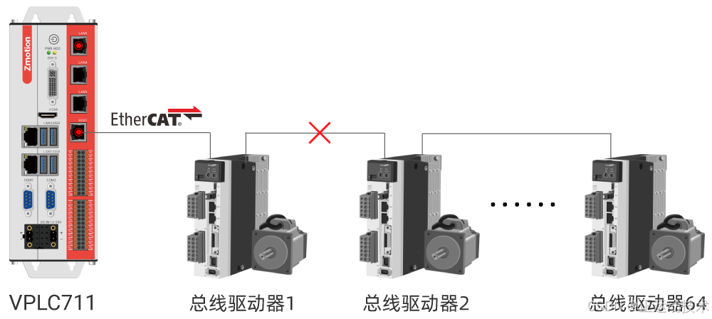
不管是哪种接线方式,线缆断线将会影响设备的正常运转,哪怕是传统的CAN、RS485等通信的设备控制也都无法正常运转。问题还得要解决,那有没有标准的、又不需要添加太多额外的设计成本,就能解决上述的问题呢?一起来看看EtherCAT总线给出的解决方案,以及EtherCAT冗余技术的实现原理。我们先看它的连接方式,如下图所示。
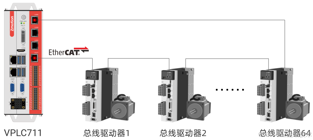
从EtherCAT的线缆冗余接线图中可以看出,复用了最后一个从站设备的OUT端接回主站,是不是有点巧妙呢?减少了硬件成本,还能解决问题,确实受大家喜欢。再来细看它的数据流向,假设还是第一个伺服和第二个伺服之间断开了,它的工作原理如下图所示。

伺服1和伺服2的线缆断开后仍与从站设备连接着,但通信线路变成两条支线,设备仍然可以正常通信,设备依然还能够继续控制运行。上述就是EtherCAT冗余的解决方案,将线型结构变成了环形结构,实现了链路冗余功能。
冗余功能的优势
01 节约设计成本
EtherCAT线缆冗余,使用了最后一个从站设备的OUT端口,使得冗余功能标准化。
02 增强系统可靠性和稳定性
工业自动化行业中通常要求总线上的设备不间断运转,不允许停止生产,冗余技术可以实现应用系统的可靠性和稳定性。
03 故障诊断与处理
当出现线缆断线时,变成两条之链路控制继续工作,同时EtherCAT可以自动检测到总线系统中的故障点,可大大简化系统的维护工作,提高了设备的维护性。
环境配置
▶ 正运动目前只有7系240520以后的版本支持。
环境准备
(1)准备一台VPLC711-i5-ETH5一体机;
(2)安装240520以上MotionRT版本;
(3)EtherCAT做主口,其他网口任选一个做从口;
(4)按照图示接线,EtherCAT接入第一个设备的in,最后一个设备的out接入VPLC711上的对应冗余网口,形成一个环路;

(5)在总线初始化过程中,SLOT_STOP总线停止后加入SLOT_SLAVE(0)=1;
(6)此时环路中任意处断开一个接口,节点运行正常;
(7)有需求可在代码中加入断线检测的指令。
RT驱动安装
第一步:安装驱动程序
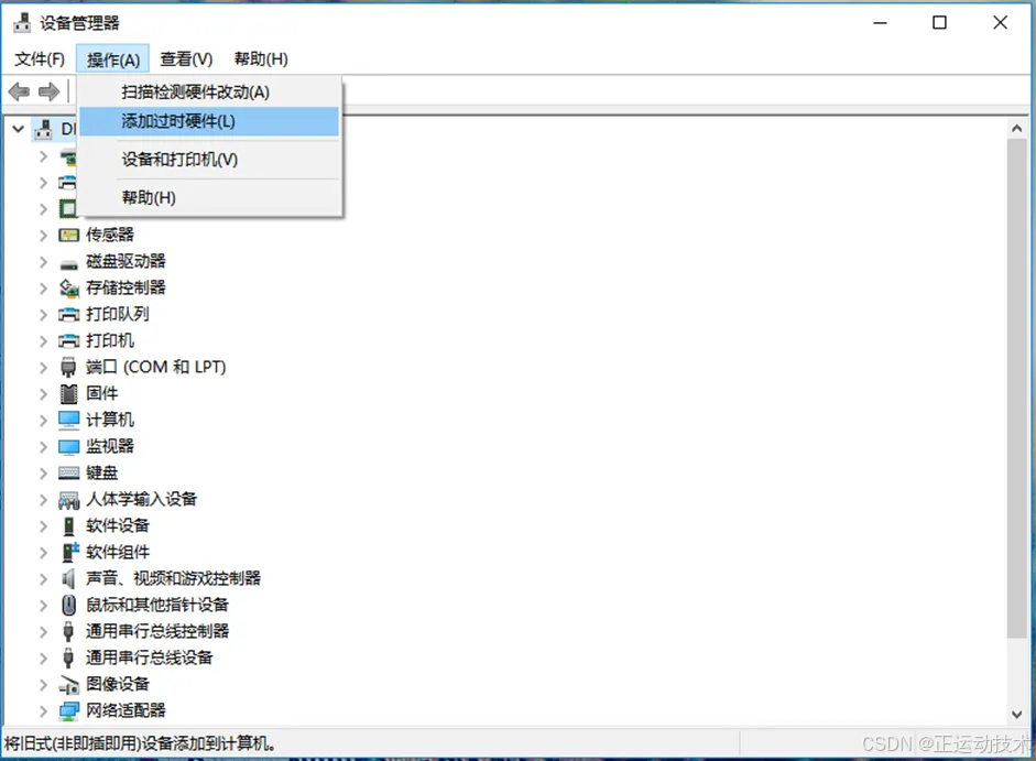
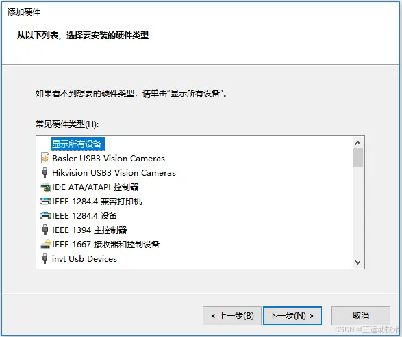
1.打开"设备管理器",选择"操作"中的"添加过时硬件",选择"手动选择"。
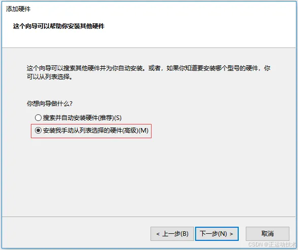
2.点击"下一步"。
3.点击"从磁盘安装"。
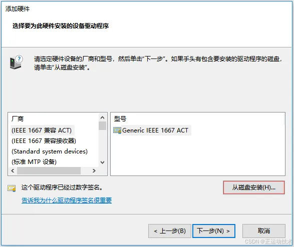
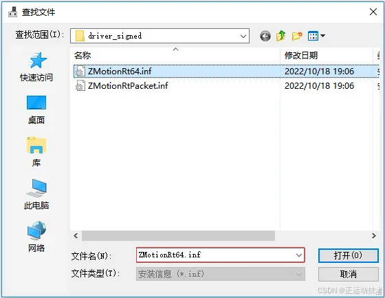
4.点击"浏览按钮"选择驱动所在的路径,打开文件夹"driver_signed",选择"ZMotionRt64.inf"。

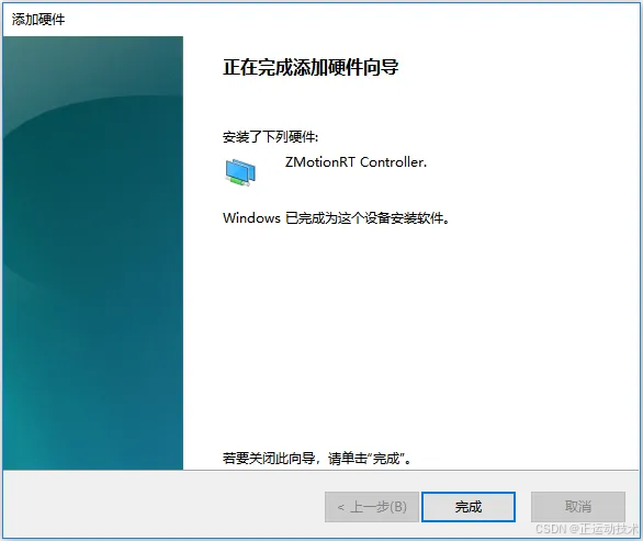
5.一直点击"下一步",直到安装完成。
注意:驱动更新时,要从设备管理器删除设备,一定要选择把驱动文件也删除。
第二步:安装EtherCAT协议
MotionRT711支持XPCI/XPCIE的ECAT网口,也支持电脑普通网口作为ECAT使用。
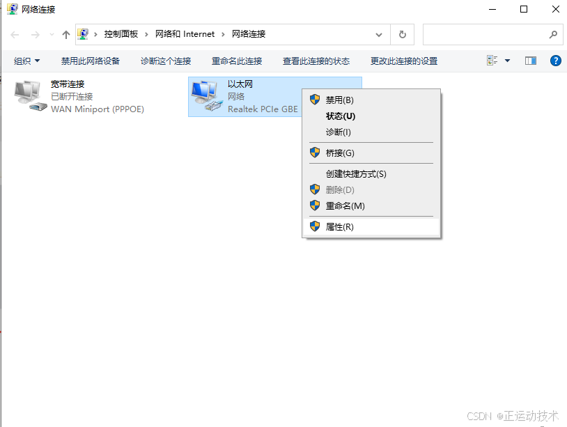
1.在Windows网络连接界面,选择需要用作冗余功能总线的网口,右击属性→安装→协议→添加。
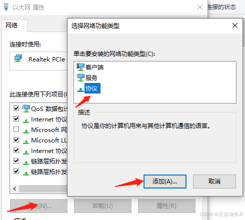
2.选择"从磁盘安装"。

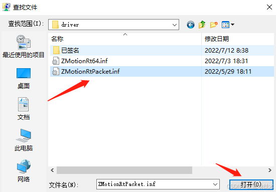
3.浏览驱动位置,选择"ZMotionRtPacket.inf"。
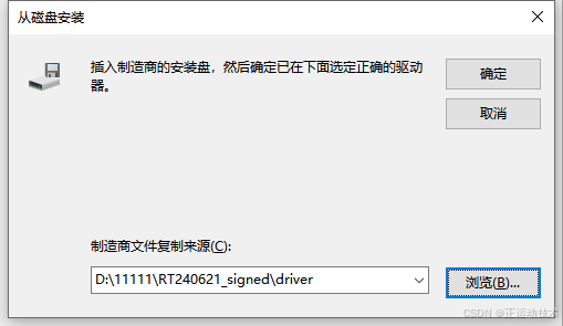
4.点击"确定"。
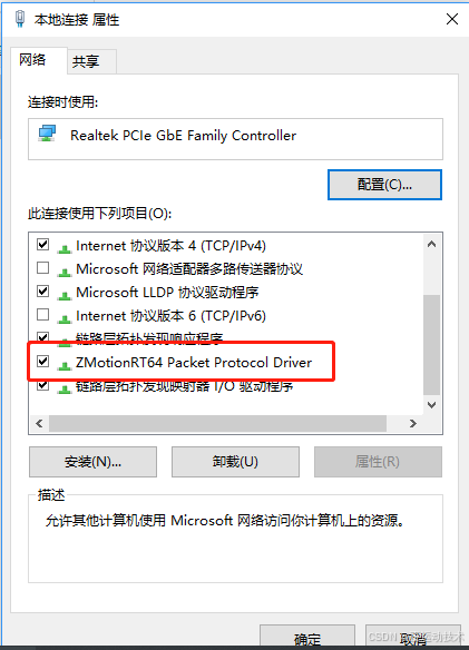
在属性中查看有ZMotionRT64 Packet Protocol Driver就是安装成功,勾选上就可以添加对应的网口总线协议。不接设备的网口可以在这里取消掉勾选。
5.添加总线协议。
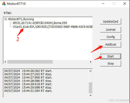
在RT7启动界面,点击"AddEcat",在EtherCAT总线列表下,将对应的冗余网口的总线增加到列表,增加成功之后,"Start"即可。如下图的标号2所示。
冗余代码指令分析
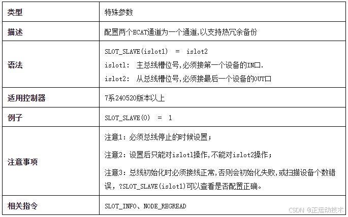
冗余指令使用方法如下所示。SLOT_SLAVE -- EtherCAT冗余配置。(该指令在总线停止时进行设置)
断线检测指令解析如下
一、SLOT_INFO和NODE_INFO
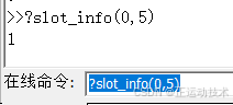
打印SLOT_INFO(slot,5)可检测到线缆是否断开,0-线缆正常,1-检测到线缆断开。NODE_INFO有相同功能。
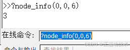
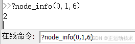
NODE_INFO(slot,node,6)也可检测到设备网口状态,按bit位操作,第0位表示IN口状态,第1位表示OUT口状态,置1为正常,置0为断开。(SLOT_INFO只能读取线路是否有断线,不能确定是哪个节点断线,NODE_INFO可以精确到某个节点断线)。如下图范例所示。
(1)表示整个环路EtherCat检测到断线。
(2)打印值为3,二进制表示为0011,Bit0和Bit1均为1,表示节点0,正常接线。
(3)打印值为2,二进制表示为0010,Bit0为0,Bit1为1,表示节点1 EtherCat In处断开。
二、NODE_REGREAD
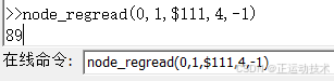
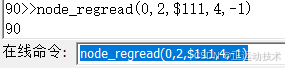
NODE_REGREAD(slot,node,address=0x111,bytes,modbusindes)可以读取到设备网口状态,从而精准判断哪个设备哪个网口断开。
正常返回为90,in处断开返回89,out处断开返回86。
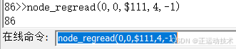
BIT0=第一个口状态(in口),BIT2=第二个口状态(out口)。只看bit0和bit2,置1为断开,置0为正常。如下图范例所示。
(1)打印值为89,二进制表示为01011001,Bit0为1,表示节点1 EtherCAT In口断开。
(2)打印值为86,二进制表示为01010110,Bit2为1,表示节点0 EtherCAT Out口断开。
(3)打印值为90,二进制表示为01011010,Bit0和Bit2均为0,表示节点2连接正常。
上位机C#检测掉线应用实例
我们通过basic脚本程序,slot_info指令循环判断是否有掉线,若掉线,则设置对应变量test的值,值为1表示掉线,为0则表示正常连接。
Basic部分程序如下图所示。(这里通过读取basic全局变量值判断,也可以通过寄存器的值判断,或者通过node_regread掉线指令检测)
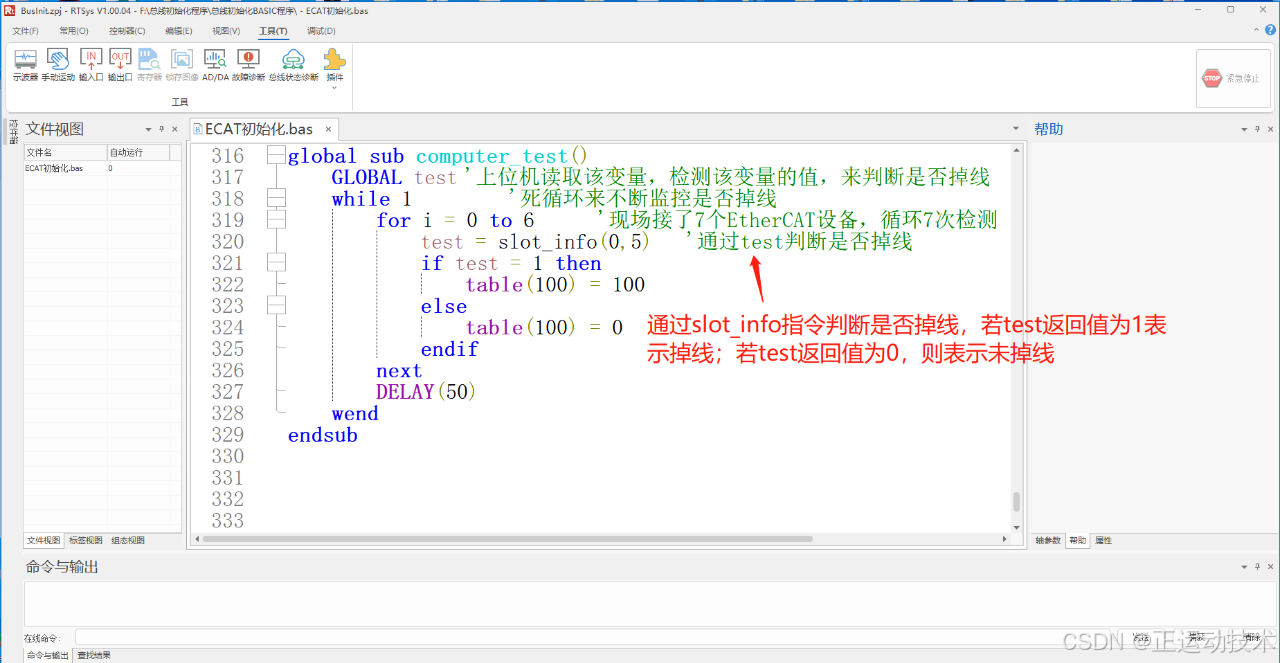
通过上述basic程序可以看到,程序循环监控,刷新slot_info指令的返回值,赋值给test变量,此时,上位机通过监控test的值的变化来判断是否有掉线,上位机显示界面如下图所示。
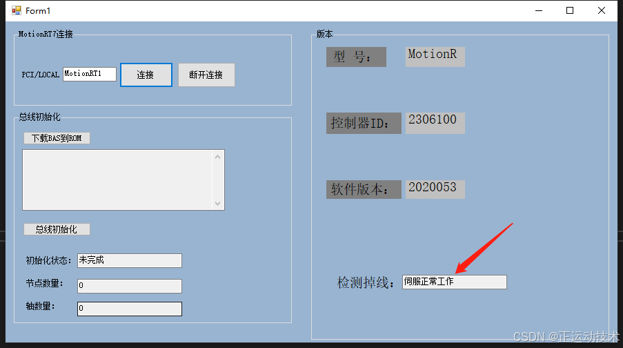
1、伺服正常工作无掉线的情况。
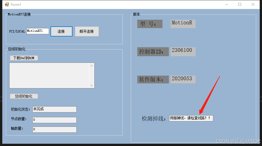
2、伺服正常工作过程中,其中一个EtherCAT节点掉线的情况。
3、相关部分程序如下图所示。
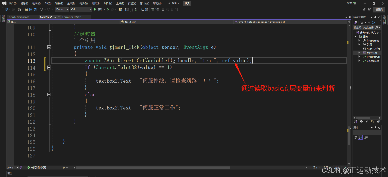
如上图可知,上位机通过相关接口实时读取basic底层变量test的值,来判断相对应的EtherCAT节点是否掉线。
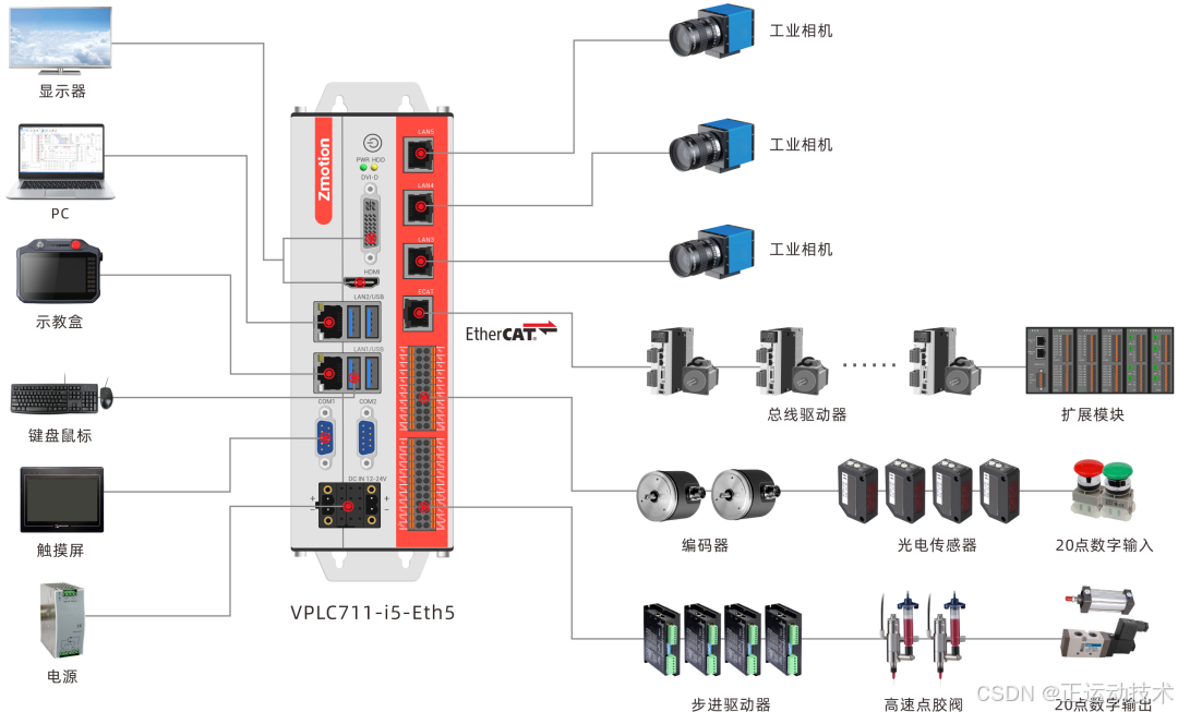
机器视觉EtherCAT运动控制器VPLC711
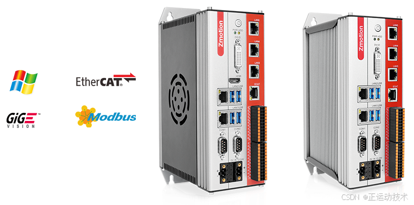
VPLC711是一款基于x86平台和Windows操作系统的高性能机器视觉EtherCAT运动控制器,具备强大的运算能力和灵活性。它具有出色的实时性能和多路高速硬件输入与多路高速PSO输出,能够精准控制多轴同步运动,并与外部设备实现多协议的高速通信。
VPLC711支持多种硬件接口和通信协议,方便与其他设备的连接和集成。除此之外,VPLC711还具备视觉处理功能,能够实时处理图像数据,实现视觉检测、测量和定位等应用。
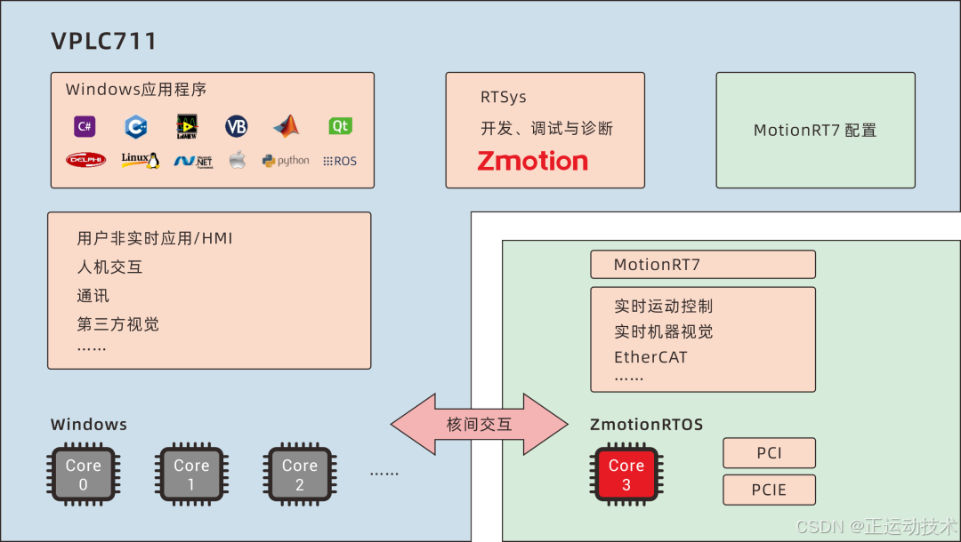
VPLC711内置Windows运动控制实时内核MotionRT7,形成一种开放式IPC形态实时软控制器/软PLC,为用户提供灵活集成的运动控制+视觉一体化解决方案。
VPLC711硬件参数
1.采用x86高性能CPU,EtherCAT可支持1ms 64轴同步运行;
2.板载RS232,RS485,EtherNet5,EtherCAT,USB3.04硬件接口;
3.板载20DI,其中4个高速色标锁存,2组高速单端编码器;
4.板载20DO,其中4个高速单端脉冲轴,4组高速PWM;
5.支持DVI-D,HDMI显示,支持双网口不同IP设置。