目录
前言
利用STM32CubeMX新建减速电机驱动工程,并且通过减速电机自带的霍尔编码器采集速度。
重点:
1、配置定时器生成PWM------控制TB6612输出;
2、配置定时器产生10ms中断------电机控制周期;
3、配置定时器为正交编码模式------采集电机转速;
4、配置GPIO------控制电机方向
一、CubeMX配置
1、系统及时钟配置
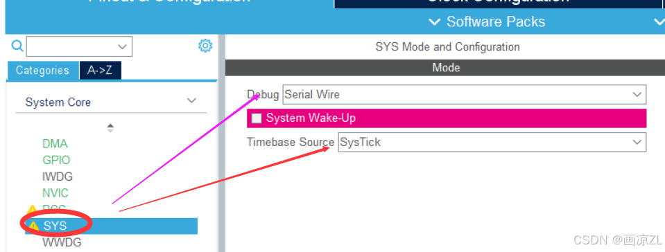
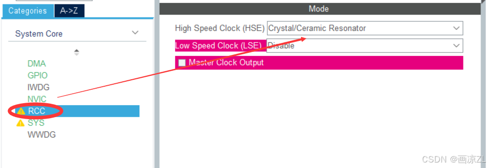
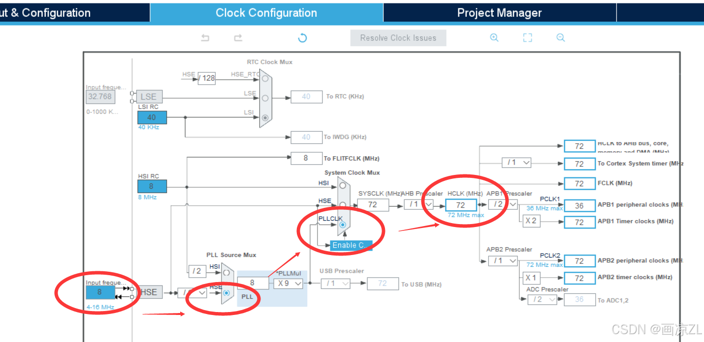
2、配置GPIO
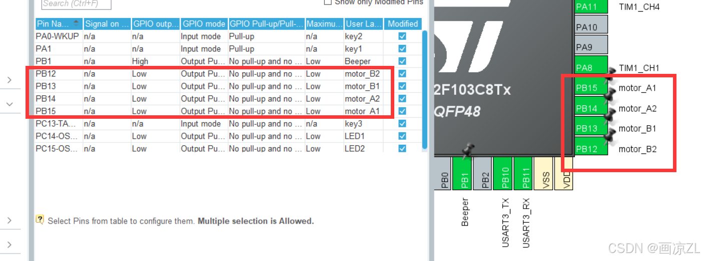
3、定时器配置
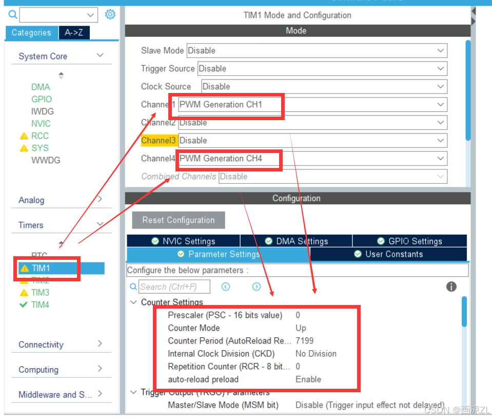
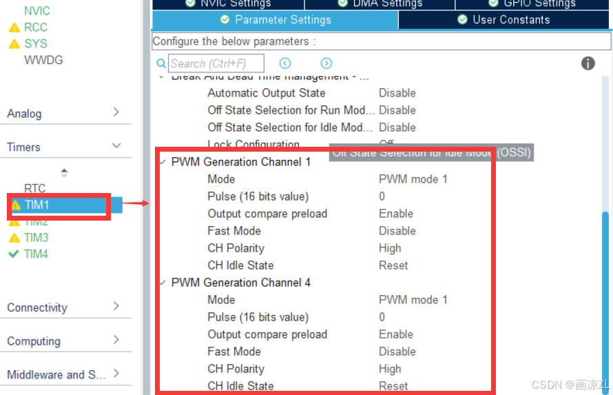
配置定时器TIM1生成PWM:
PSC = 0;
ARR = 7199;
由于系统时钟为72M,所以PWM频率为:10kHz。
占空比为:D=Pulse/ARR * 100%。
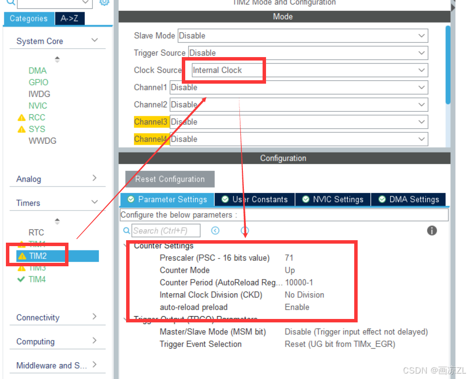
配置定时器TIM2产生10ms中断:
PSC = 72-1;
ARR = 10000-1;
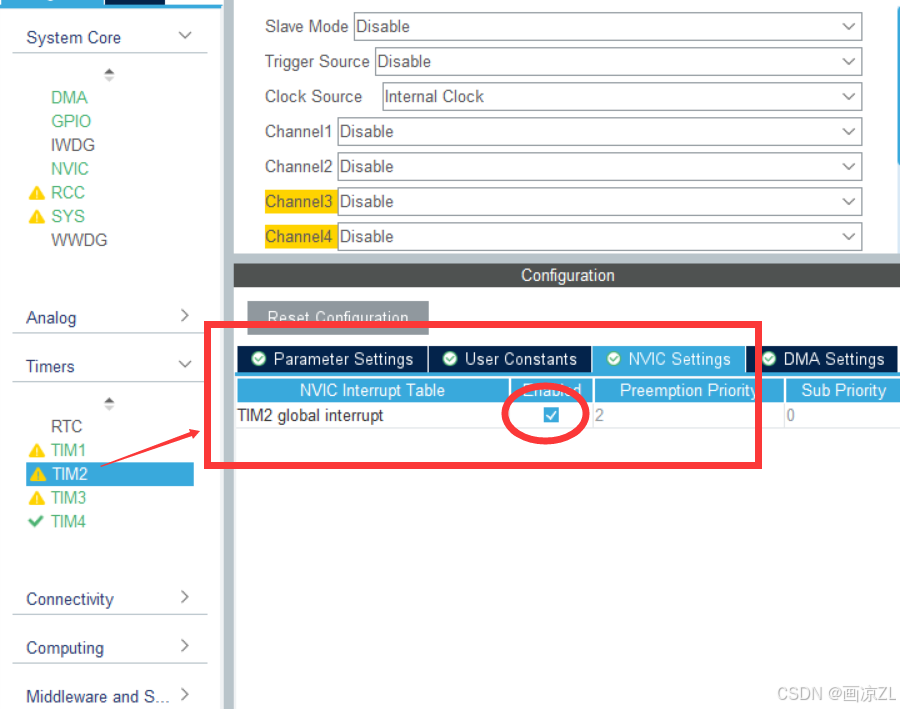
同时 需要开启定时器中断,中断优先级自己设置。
配置定时器TIM3、TIM4为正交编码模式:
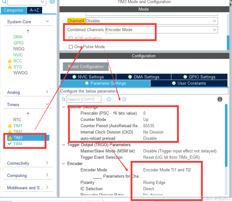
定时器TIM3和TIM4操作一样,如果有需要可以自行开启定时器更新中断。
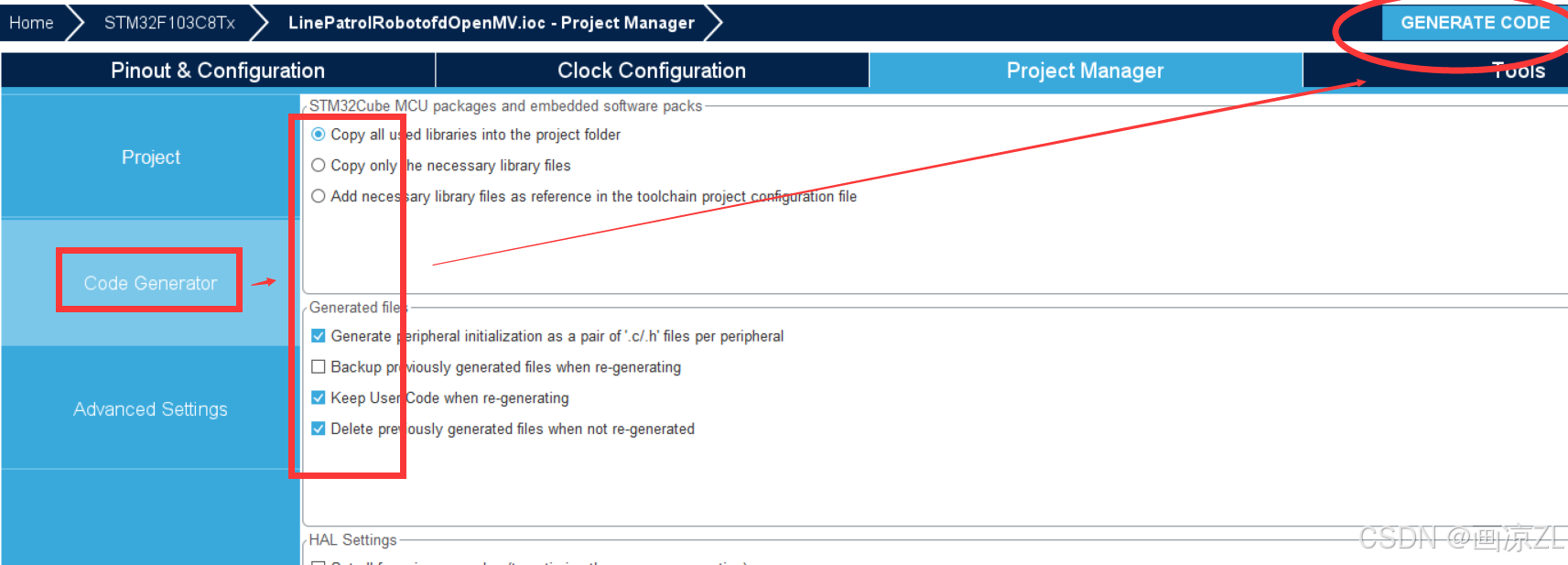
4、生成MDK工程

其中工程名字和路径都不能有中文,必须用标准C的标识符命名。
二、Keil编辑代码
1.初始化代码
通过CubeMX配置生成的工程还需要加入一些初始化代码:
cpp
HAL_TIM_Encoder_Start(&htim3, TIM_CHANNEL_ALL);
HAL_TIM_Encoder_Start(&htim4, TIM_CHANNEL_ALL);

 HAL_TIM_Base_Start_IT(&htim2);

 HAL_TIM_PWM_Start(&htim1,TIM_CHANNEL_1);
 HAL_TIM_PWM_Start(&htim1,TIM_CHANNEL_4);
 __HAL_TIM_SetCompare(&htim1,TIM_CHANNEL_1,0);
 __HAL_TIM_SetCompare(&htim1,TIM_CHANNEL_4,0);
2.电机控制代码
这里主要采用TB6612来驱动减速电机:
motor.h文件代码如下
cpp
#ifndef  _MOTOR_H_
#define  _MOTOR_H_

#include "stm32f1xx_hal.h"
#include "tim.h"


/*******直流减速电机机械参数*********/
#define ENCODE_X 500 //编码器线数
#define JIANSUBI 30		//减速比
#define BEIPIN 4			//倍频
#define SAMPLE_TIME 0.01  //采样时间10ms
#define C (ENCODE_X*JIANSUBI*BEIPIN*SAMPLE_TIME)

#define PI 3.1415
#define R  6.5   //车轮直径cm

#define BIN2(n)  HAL_GPIO_WritePin(GPIOB,GPIO_PIN_13 , (GPIO_PinState)n)
#define BIN1(n)  HAL_GPIO_WritePin(GPIOB,GPIO_PIN_12 , (GPIO_PinState)n)
#define AIN2(n)  HAL_GPIO_WritePin(GPIOB,GPIO_PIN_15 , (GPIO_PinState)n)
#define AIN1(n)  HAL_GPIO_WritePin(GPIOB,GPIO_PIN_14 , (GPIO_PinState)n)

typedef struct
{
    float speed;
    int S;
    int Target_Speed;
    int out;
}MOTOR_t;
extern MOTOR_t motorA,motorB;

#define LIMIT(x,min,max) (x)=(((x)<=(min))?(min):(((x)>=(max))?(max):(x)))  //限幅定义
int abs(int p);
void Load(int motorA,int motorB);


#endif
其中电机以及轮子的参数自己修改。
motor.c文件代码如下
cpp
#include "motor.h"

MOTOR_t motorA = {0},motorB = {0};

int abs(int p)
{
	int q;
	q=p>0?p:(-p);
	return q;
}

void Load(int motorA,int motorB)
{
    LIMIT(motorA,-7199,7199);
    LIMIT(motorB,-7199,7199);
	if(motorA>0)
		AIN1(1),AIN2(0);//正转
	else
		AIN1(0),AIN2(1);//正转

	__HAL_TIM_SetCompare(&htim1, TIM_CHANNEL_1, abs(motorA));

	if(motorB>0)
		BIN1(1),BIN2(0);
	else
		BIN1(0),BIN2(1);
	__HAL_TIM_SetCompare(&htim1, TIM_CHANNEL_4,  abs(motorB));

}
3、电机测速代码
cpp
float get_speed_motorA()
{

    short Encoder_TIM = 0;
    float Speed = 0.0;
    Encoder_TIM = (short)__HAL_TIM_GetCounter(&htim3);       //获取编码器定时器中的计数值
    __HAL_TIM_SetCounter(&htim3, 0);

    if(htim3.Instance->CR1 & 0X10) //判断计数器的计数方向,逻辑1则是减计数
    {
        Encoder_TIM = -65536 + Encoder_TIM;
    }
//    Encoder_TIM = Encoder_TIM+Encoder3_Overflow_Count*65536;
    Speed = (float)Encoder_TIM / (C) * PI * R;
    return Speed;
}

float get_speed_motorB()
{
    short Encoder_TIM = 0;
    float Speed = 0.0;
    Encoder_TIM = (short)__HAL_TIM_GetCounter(&htim4);       //获取编码器定时器中的计数值
    __HAL_TIM_SetCounter(&htim4, 0);

    if(htim4.Instance->CR1 & 0X10) //判断计数器的计数方向,逻辑1则是减计数
    {
        Encoder_TIM = -65536 + Encoder_TIM;
    }
//    Encoder_TIM = Encoder_TIM+Encoder3_Overflow_Count*65536;
    Speed = -(float)Encoder_TIM / (C) * PI * R;
    return Speed;
}
在定时器中断里, 每10毫秒对定时器TIM3和TIM4的计数值进行处理,得到电机速度,方便后续进行速度闭环控制。
4、控制示例
cpp
int main(void)
{
  /* USER CODE BEGIN 1 */

  /* USER CODE END 1 */

  /* MCU Configuration--------------------------------------------------------*/

  /* Reset of all peripherals, Initializes the Flash interface and the Systick. */
  HAL_Init();

  /* USER CODE BEGIN Init */

  /* USER CODE END Init */

  /* Configure the system clock */
  SystemClock_Config();

  /* USER CODE BEGIN SysInit */

  /* USER CODE END SysInit */

  /* Initialize all configured peripherals */
  MX_GPIO_Init();
  MX_TIM1_Init();
  MX_TIM2_Init();
  MX_TIM3_Init();
  MX_TIM4_Init();
  /* USER CODE BEGIN 2 */
    HAL_TIM_Encoder_Start(&htim3, TIM_CHANNEL_ALL);
    HAL_TIM_Encoder_Start(&htim4, TIM_CHANNEL_ALL);

    HAL_TIM_Base_Start_IT(&htim2);

    HAL_TIM_PWM_Start(&htim1,TIM_CHANNEL_1);
    HAL_TIM_PWM_Start(&htim1,TIM_CHANNEL_4);
    __HAL_TIM_SetCompare(&htim1,TIM_CHANNEL_1,0);
    __HAL_TIM_SetCompare(&htim1,TIM_CHANNEL_4,0);
  /* USER CODE END 2 */

  /* Infinite loop */
  /* USER CODE BEGIN WHILE */
  while (1)
  {
    /* USER CODE END WHILE */

    /* USER CODE BEGIN 3 */
            motorA.out = 20;
            motorB.out = -20;
  }
  /* USER CODE END 3 */
}

void HAL_TIM_PeriodElapsedCallback(TIM_HandleTypeDef *htim)
{
/*******电机控制周期,每十秒对电机控制一次*********/
    if(htim->Instance == TIM2 )
    {
            motorA.speed = get_speed_motorA();
            motorB.speed = get_speed_motorB();
            motorA.S += motorA.speed;
            motorB.S += motorB.speed;

        Load(motorA.out, motorB.out);
    }

}
总结
通过本文,就可以对减速电机进行简单的控制,以及速度的采集了。
同时可以自行加入OLED等显示屏,显示所采集的速度,也可以通过配置串口进行打印观察。