数码管简介
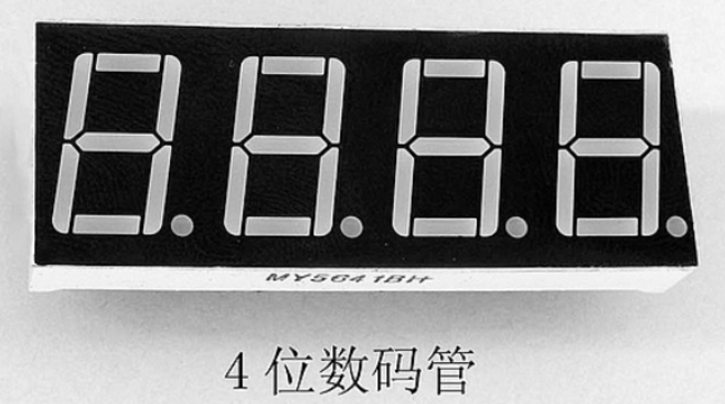
数码管每段其本质就是个LED灯,只需要控制特定的LED灯亮就能显示数据。普中开发版所使用的是两个并在一起共阴极 连接的"4位数码管",可以同时显示8个数字。数码管的显示可以分成静态显示和动态显示,这里先介绍最简单的静态显示。
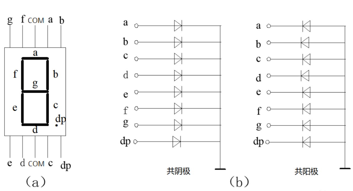
数码管分为共阴极连接和共阳极连接,顾名思义共阴极就是把所有的数码管阴极连接在一起,共阳极就是把数码管所有的阳极连接在一起,之所以这么做是为了节省单片机I/O口。
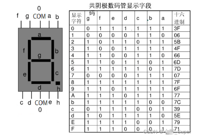
图(a)是数码管段选位图,以普中51单片机开发版为例,它的数码管采用共阴极(低电平0)连接,所以如果我们想让一个数码管显示数字6,就应当在相应段选位设置为高电平(1),其余设置为低电平(0),如图所示:
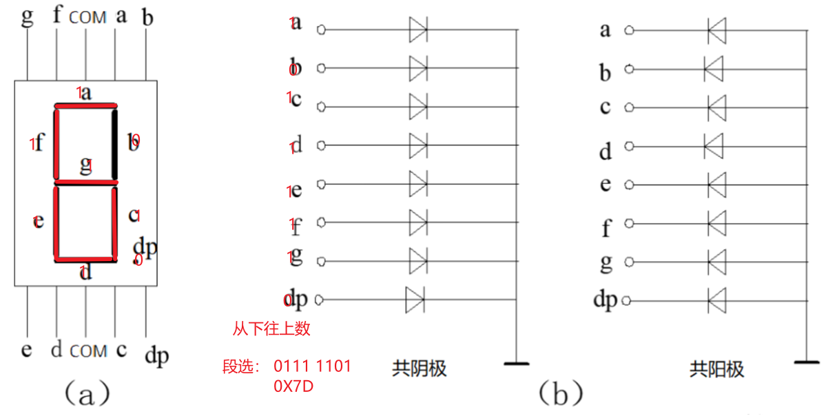
下图是共阴极数码管显示0-F对应的编码(表中省略了dp段0):
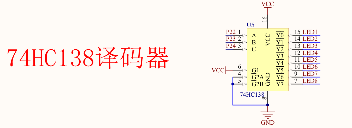
74HC138译码器简介
作用:节省单片机I/O口
C
//这里结合两张图片一起介绍
// P2_4 = 1;P2_3 = 1;P2_2 = 1;  控制LED8
// P2_4 = 1;P2_3 = 1;P2_2 = 0;  控制LED7
// P2_4 = 1;P2_3 = 0;P2_2 = 1;  控制LED6
// P2_4 = 1;P2_3 = 0;P2_2 = 0;  控制LED5
// P2_4 = 0;P2_3 = 1;P2_2 = 1;  控制LED4
// P2_4 = 0;P2_3 = 1;P2_2 = 0;  控制LED3
// P2_4 = 0;P2_3 = 0;P2_2 = 1;  控制LED2
// P2_4 = 0;P2_3 = 0;P2_2 = 0; 控制LED1 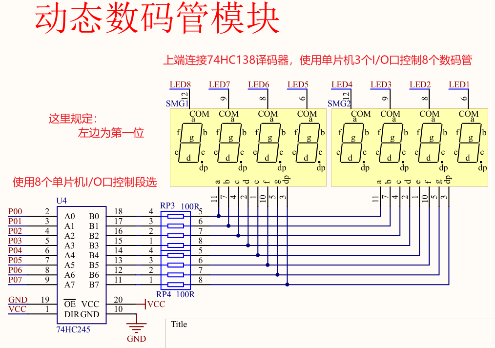
到此知识准备结束,现在可以编写第一个程序了。
静态数码管显示
C
#include<regx52.h>
unsigned char Table[] = {0X3F,0X06,0X5B,0X4F,0X66,0X6D,0X7D,0X07,0X7F,0X6F}; // 数组,定义数字0~9段选
void SMG(unsigned char Location,Number) // 定义函数,参数Location是位选,Number段选控制显示的数字。
{
switch(Location) // 位选
{
case 1 : P2_4 = 1;P2_3 = 1;P2_2 = 1;break;
case 2 : P2_4 = 1;P2_3 = 1;P2_2 = 0;break;
case 3 : P2_4 = 1;P2_3 = 0;P2_2 = 1;break;
case 4 : P2_4 = 1;P2_3 = 0;P2_2 = 0;break;
case 5 : P2_4 = 0;P2_3 = 1;P2_2 = 1;break;
case 6 : P2_4 = 0;P2_3 = 1;P2_2 = 0;break;
case 7 : P2_4 = 0;P2_3 = 0;P2_2 = 1;break;
case 8 : P2_4 = 0;P2_3 = 0;P2_2 = 0;break;
}
P0 = Table[Number]; // 段选
}
void main()
{
// P2_2 = 1; // 这是我做的小实验,不要过多关注
// P2_3 = 1;
// P2_4 = 0;
// P0 = 0X7D; // 这块板子共阴极数码管,38译码器和SMG都是从下往上数
while(1)
{
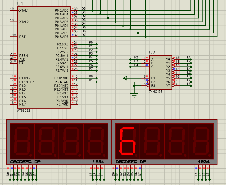
SMG(5,6); // 第五位显示数字6
}
}实验现象:(Proteus仿真中P0端口要有个上拉电阻,这里没截到)
动态数码管显示
原理:快速扫描逐个显示,利用人眼的余辉效应显示多个数码管,实际上在一个时刻内只有一个数码管点亮。
C
#include<regx52.h>

unsigned char Table[] = {0X3F,0X06,0X5B,0X4F,0X66,0X6D,0X7D,0X07,0X7F,0X6F};

void Delay(unsigned int n)  // 延时函数
{
	unsigned char j;
	while(n--)
	{
		for(j = 0; j< 113; j++);
	}
}

void SMG(unsigned char Location,Number)
{
	switch(Location) // 段选
	{
		case 1 : P2_4 = 1;P2_3 = 1;P2_2 = 1;break;
		case 2 : P2_4 = 1;P2_3 = 1;P2_2 = 0;break;
		case 3 : P2_4 = 1;P2_3 = 0;P2_2 = 1;break;
		case 4 : P2_4 = 1;P2_3 = 0;P2_2 = 0;break;
		case 5 : P2_4 = 0;P2_3 = 1;P2_2 = 1;break;
		case 6 : P2_4 = 0;P2_3 = 1;P2_2 = 0;break;
		case 7 : P2_4 = 0;P2_3 = 0;P2_2 = 1;break;
		case 8 : P2_4 = 0;P2_3 = 0;P2_2 = 0;break;
	}
	P0 = Table[Number];				// 位选
	Delay(1);					// 数码管显示1ms后关闭
	P0 = 0X00;					// 消影清零,防止上次的数据窜位重影
}
void main()
{
	while(1)
	{
		SMG(1,1); // 位选 段选
		SMG(2,2);
	        SMG(3,3);
	}
}
实验现象: