code repo: 访问gitee
就像写代码的Hello world一样,点亮LED往往是嵌入式开发的第一步。
硬件连接
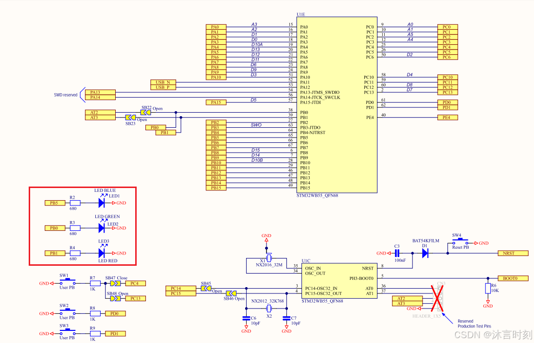
从原理图上可以看到,该板子上有3个不同颜色的led,以blue led为例,led负极接地,控制GPIO为PB5,高电平点亮,低电平熄灭。
代码开发
代码中有大量的如下注释
c
  /* USER CODE BEGIN Init */
  /* USER CODE END Init */
这种注释为了cubeMX服务的。如果使用了stm32cubeMX来生成项目和code,就会将cubeMX对应保存为ioc格式。就像一个cubeMX工程。如果使用cubemx来更新配置和设计,就会更新code,当code写在这两行注释之间,就会保留,而写在这两行注释之外的code,就会因为cubeMX的更新code而丢失。
由于这里使用手动创建工程,不适用cubeMX,因此该注释可忽略或者删除。
程序运行
使用USB线连接PC和开发板的st-link接口。
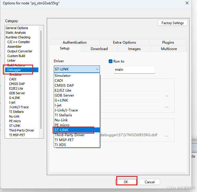
程序首次编译完成后,默认是simulator方式,因此首先更改下载方式使其能够在硬件上运行。
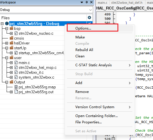
方法是右键项目名,选择options:
修改code
- 因为板子上有外部晶振,外部晶振一般更准确,所以设置使用HSE外部时钟。
c
void SystemClock_Config(void)
{
  RCC_OscInitTypeDef RCC_OscInitStruct = {0};
  RCC_ClkInitTypeDef RCC_ClkInitStruct = {0};

  /** Configure the main internal regulator output voltage
  */
  __HAL_PWR_VOLTAGESCALING_CONFIG(PWR_REGULATOR_VOLTAGE_SCALE1);

  /** Initializes the RCC Oscillators according to the specified parameters
 * in the RCC_OscInitTypeDef structure.
  */
  RCC_OscInitStruct.OscillatorType = RCC_OSCILLATORTYPE_HSE;
  RCC_OscInitStruct.HSEState = RCC_HSE_ON;
  RCC_OscInitStruct.LSEState = RCC_LSE_ON;
  RCC_OscInitStruct.HSIState = RCC_HSI_ON;
  RCC_OscInitStruct.HSICalibrationValue = RCC_HSICALIBRATION_DEFAULT;
  RCC_OscInitStruct.PLL.PLLState = RCC_PLL_NONE;
  if (HAL_RCC_OscConfig(&RCC_OscInitStruct) != HAL_OK)
  {
    Error_Handler();
  }

  /** Configure the SYSCLKSource, HCLK, PCLK1 and PCLK2 clocks dividers
  */
  RCC_ClkInitStruct.ClockType = RCC_CLOCKTYPE_HCLK4|RCC_CLOCKTYPE_HCLK2
                              |RCC_CLOCKTYPE_HCLK|RCC_CLOCKTYPE_SYSCLK
                              |RCC_CLOCKTYPE_PCLK1|RCC_CLOCKTYPE_PCLK2;
  RCC_ClkInitStruct.SYSCLKSource = RCC_SYSCLKSOURCE_HSE;
  RCC_ClkInitStruct.AHBCLKDivider = RCC_SYSCLK_DIV1;
  RCC_ClkInitStruct.APB1CLKDivider = RCC_HCLK_DIV1;
  RCC_ClkInitStruct.APB2CLKDivider = RCC_HCLK_DIV1;
  RCC_ClkInitStruct.AHBCLK2Divider = RCC_SYSCLK_DIV2;
  RCC_ClkInitStruct.AHBCLK4Divider = RCC_SYSCLK_DIV1;

  if (HAL_RCC_ClockConfig(&RCC_ClkInitStruct, FLASH_LATENCY_3) != HAL_OK)
  {
    Error_Handler();
  }
}- 初始化和点亮led。 这段代码很简单,可以自己写,也可以调用bsp的接口。为节约时间,在main中调用bsp的接口实现。
c
int main(void)
{
/* MCU Configuration--------------------------------------------------------*/
/* Reset of all peripherals, Initializes the Flash interface and the Systick. */
HAL_Init();
/* Configure the system clock */
SystemClock_Config();
BSP_LED_Init(LED1);
BSP_LED_On(LED1);
/* Initialize all configured peripherals */
while (1)
{
}
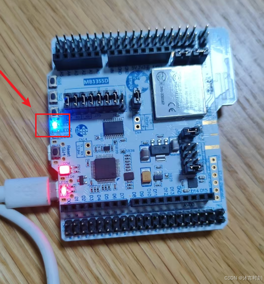
}效果如图:
code repo: 访问gitee
code commit: 388241a9f09ab96eede33f8a1b9ee110100f1442
The End!