目录
[1 前言](#1 前言)
[2 项目环境](#2 项目环境)
[2.1 硬件准备](#2.1 硬件准备)
[2.2 软件环境](#2.2 软件环境)
[3 硬件连接和方案](#3 硬件连接和方案)
[3.1 W55MH32Q-EVB 硬件连接](#3.1 W55MH32Q-EVB 硬件连接)
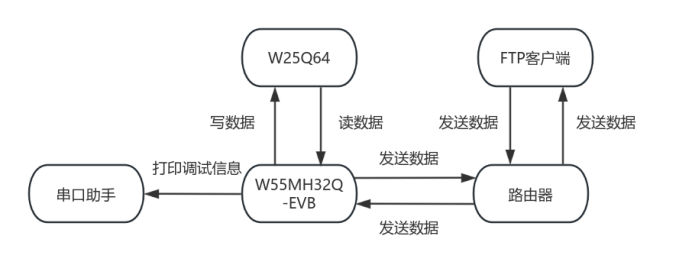
[3.2 方案图示](#3.2 方案图示)
[4 例程修改](#4 例程修改)
1 前言
FTP(File Transfer Protocol,文件传输协议)是遵循文件传输协议(FTP),在网络中提供文件传输服务的重要组件。它采用客户端 - 服务器架构,工作模式分为主动和被动。主动模式下,服务器主动发起数据连接;被动模式中,由客户端发起数据连接。用户访问时,需进行身份验证,常见方式是输入用户名和密码,部分服务器也支持匿名登录。
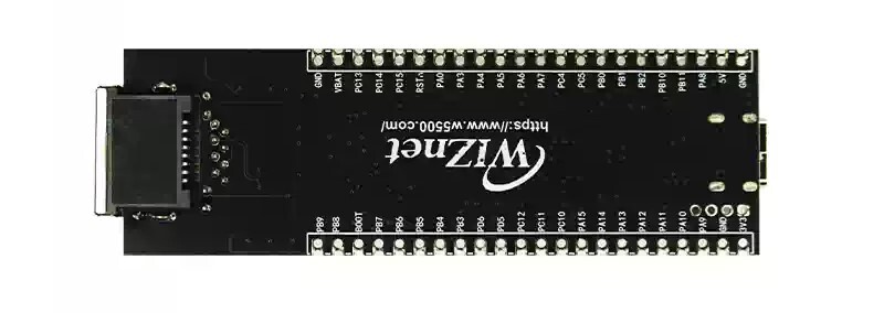
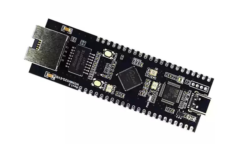
W55MH32Q-EVB 是基于 W55MH32Q芯片开发的一款开发板,主频为 216MHz,1MB 的闪存以及 96KB 的 SRAM,同时还具有一个完整的硬件 TCP/IP 卸载引擎,只需要简单的 socket 编程即可实现以太网应用。 具有以下特点:
- 增强型、真随机数、硬件加密算法单元
- 32 位 Arm® Cortex®-M3 核心的片上
- 1024K 字节闪存的微控制器
- 10/100M 以太网 MAC 和 PHY、集成完整的全硬件 TCP/IP 协议栈引擎
- USB、CAN、17 个定时器
- 3 个 ADC、2 个 DAC、12 个通信接口
产品链接:商品详情
2 项目环境
2.1 硬件准备
- W55MH32Q-EVB 模块
- 杜邦线若干
- 交换机或路由器
- W25Q64 模块
- 一根网线
2.2 软件环境
3 硬件连接和方案
3.1 W55MH32Q-EVB 硬件连接
1.W55MH32Q-EVB_3.3V ---> W25Q64_VCC`
`2.W55MH32Q-EVB_GND ---> W25Q64_GND`
`3.W55MH32Q-EVB_PA4 ---> OLED_CS`
`4.W55MH32Q-EVB_PA5 ---> OLED_SCK`
`5.W55MH32Q-EVB_PA6 ---> OLED_MISO`
`6.W55MH32Q-EVB_PA7 ---> OLED_MOSI
3.2 方案图示
4 例程修改
本次以 FTP_Server 例程为例。
由于 ftp.c 文件代码较长,修改较多,且分散,所以我上传到了百度网盘,访问链接获取 ftpd.c 文件。
将下载好的文件替换掉例程中的 ftpd.c 文件,并在 ftpd.h 中启用 F_FILESYSTEM 这个宏定义。
创建文件 w25qxx.c,用于驱动 W25Q64,代码如下:
#include "w25qxx.h"`
`#include "delay.h"`

`u16 W25QXX_TYPE` `=` `W25Q128;` `// The default is W25Q128.`

`// SPIx reads and writes a byte`
`// TxData: Bytes to write`
`// Return value: bytes read`
`u8 SPI_ReadWriteByte(u8 TxData)`
`{`
`    u8 retry =` `0;`
    `while` `(SPI_I2S_GetFlagStatus(SPI1,` `SPI_I2S_FLAG_TXE)` `==` `RESET)` `// Check whether the specified SPI flag is set or not: Send cache null flag`
    `{`
`        retry++;`
        `if` `(retry >` `200)`
            `return` `0;`
    `}`
    `SPI_I2S_SendData(SPI1, TxData);` `// Send a data via peripheral SPIx`
`    retry =` `0;`

    `while` `(SPI_I2S_GetFlagStatus(SPI1,` `SPI_I2S_FLAG_RXNE)` `==` `RESET)` `// Check whether the specified SPI flag is set or not: Accept cache non-empty flags`
    `{`
`        retry++;`
        `if` `(retry >` `200)`
            `return` `0;`
    `}`
    `return` `SPI_I2S_ReceiveData(SPI1);` `// Returns the most recently received data via SPIx`
`}`

`void` `SPI_InitTest(void)`
`{`
`    GPIO_InitTypeDef GPIO_InitStructure;`
`    SPI_InitTypeDef SPI_InitStructure;`

    `RCC_APB2PeriphClockCmd(RCC_APB2Periph_GPIOA,` `ENABLE);` `// PORT Aclock enable`
    `RCC_APB2PeriphClockCmd(RCC_APB2Periph_SPI1,` `ENABLE);`  `// SPI1 clock enable`

`    GPIO_InitStructure.GPIO_Pin = GPIO_Pin_4;`
`    GPIO_InitStructure.GPIO_Mode = GPIO_Mode_Out_PP;`
`    GPIO_InitStructure.GPIO_Speed = GPIO_Speed_50MHz;`
    `GPIO_Init(GPIOA,` `&GPIO_InitStructure);`
    `GPIO_SetBits(GPIOA, GPIO_Pin_4);`

    `W25QXX_CS` `=` `1;` `// SPI FLASH not selected`

`    GPIO_InitStructure.GPIO_Pin = GPIO_Pin_5 | GPIO_Pin_6 | GPIO_Pin_7;`
`    GPIO_InitStructure.GPIO_Mode = GPIO_Mode_AF_PP;` `// PA/5/6/7 Multiplexed push-pull output`
`    GPIO_InitStructure.GPIO_Speed = GPIO_Speed_50MHz;`
    `GPIO_Init(GPIOA,` `&GPIO_InitStructure);` `// Initialize GPIOA`

    `GPIO_SetBits(GPIOA, GPIO_Pin_5 | GPIO_Pin_6 | GPIO_Pin_7);` `// PA5/6/7 pull up`

`    SPI_InitStructure.SPI_Direction = SPI_Direction_2Lines_FullDuplex;`   `// Set SPI to one-way or two-way data mode: SPI is set to 2 lines full duplex`
`    SPI_InitStructure.SPI_Mode = SPI_Mode_Master;`                        `// Set SPI working mode: Set the Master`
`    SPI_InitStructure.SPI_DataSize = SPI_DataSize_8b;`                    `// Set the data size of the SPI: SPI sends and receives 8-bit frame structures`
`    SPI_InitStructure.SPI_CPOL` `= SPI_CPOL_High;`                          `// The idle state of the serial synchronous clock is high`
`    SPI_InitStructure.SPI_CPHA` `= SPI_CPHA_2Edge;`                         `// The second hop edge (up or down) of the serial synchronization clock is sampled`
`    SPI_InitStructure.SPI_NSS` `= SPI_NSS_Soft;`                            `// NSS signals are managed by hardware (NSS pins) or software (using SSI bits): Internal NSS signals are controlled by SSI bits`
`    SPI_InitStructure.SPI_BaudRatePrescaler = SPI_BaudRatePrescaler_256;` `// Define the value of the baud rate prescaler: The baud rate prescaler is 256.`
`    SPI_InitStructure.SPI_FirstBit = SPI_FirstBit_MSB;`                   `// Specify whether the data transfer starts with the MSB bit or the LSB bit: Data transfer starts with the MSB bit`
`    SPI_InitStructure.SPI_CRCPolynomial =` `7;`                             `// Polynomial for CRC Value Calculation`
    `SPI_Init(SPI1,` `&SPI_InitStructure);`                                  `// Initializes peripheral SPIx registers according to the parameters specified in the SPI_InitStruct`

    `SPI_Cmd(SPI1,` `ENABLE);` `// enable SPI peripherals`

    `SPI_ReadWriteByte(0xff);` `// Initiate transfer`
`}`
`// SPI speed setting function`
`// SpeedSet:`
`// SPI_BaudRatePrescaler_2   2 division`
`// SPI_BaudRatePrescaler_8   8 division`
`// SPI_BaudRatePrescaler_16  16 division`
`// SPI_BaudRatePrescaler_256 256 division`

`void` `SPI_SetSpeed(u8 SPI_BaudRatePrescaler)`
`{`
    `assert_param(IS_SPI_BAUDRATE_PRESCALER(SPI_BaudRatePrescaler));`
    `SPI1->CR1` `&=` `0XFFC7;`
    `SPI1->CR1` `|= SPI_BaudRatePrescaler;`
    `SPI_Cmd(SPI1,` `ENABLE);`
`}`

`// Read the status register of the W25QXX`
`// BIT7 6 5 4 3 2 1 0`
`// SPR RV TB BP2 BP1 BP0 WEL BUSY`
`// SPR: default 0, status register protection bit, used with WP`
`// TB, BP2, BP1, BP0: FLASH regional write protection settings`
`// WEL: Write enable lock`
`// BUSY: busy flag bit (1, busy; 0, idle)`
`// Default: 0x00`
`u8 W25QXX_ReadSR(void)`
`{`
`    u8 byte =` `0;`
    `W25QXX_CS` `=` `0;`                         `// enable device`
    `SPI_ReadWriteByte(W25X_ReadStatusReg);` `// Send read status register command`
`    byte =` `SPI_ReadWriteByte(0Xff);`        `// Read a byte`
    `W25QXX_CS` `=` `1;`                         `// Cancel selection`
    `return byte;`
`}`
`// Write the W25QXX status register`
`// Only SPR, TB, BP2, BP1, BP0 (bit 7, 5, 4, 3, 2) can be written!!!`
`void` `W25QXX_Write_SR(u8 sr)`
`{`
    `W25QXX_CS` `=` `0;`                          `// enable device`
    `SPI_ReadWriteByte(W25X_WriteStatusReg);` `// Send write status register command`
    `SPI_ReadWriteByte(sr);`                  `// Write a byte`
    `W25QXX_CS` `=` `1;`                          `// Cancel selection`
`}`
`// W25QXX write enable`
`// set WEL`
`void` `W25QXX_Write_Enable(void)`
`{`
    `W25QXX_CS` `=` `0;`                       `// enable device`
    `SPI_ReadWriteByte(W25X_WriteEnable);` `// Send write enable`
    `W25QXX_CS` `=` `1;`                       `// Cancel selection`
`}`
`// W25QXX write disabled`
`// Clear WEL`
`void` `W25QXX_Write_Disable(void)`
`{`
    `W25QXX_CS` `=` `0;`                        `// enable device`
    `SPI_ReadWriteByte(W25X_WriteDisable);` `// Send write ban command`
    `W25QXX_CS` `=` `1;`                        `// Cancel selection`
`}`
`// Read the chip ID`
`// The return value is as follows:`
`// 0XEF13, indicating that the chip model is W25Q80.`
`// 0XEF14, indicating that the chip model is W25Q16.`
`// 0XEF15, indicating that the chip model is W25Q32`
`// 0XEF16, indicating that the chip model is W25Q64.`
`// 0XEF17, indicating that the chip model is W25Q128`
`u16 W25QXX_ReadID(void)`
`{`
`    u16 Temp =` `0;`
    `W25QXX_CS` `=` `0;`
    `SPI_ReadWriteByte(0x90);` `// Send Read ID command`
    `SPI_ReadWriteByte(0x00);`
    `SPI_ReadWriteByte(0x00);`
    `SPI_ReadWriteByte(0x00);`
`    Temp |=` `SPI_ReadWriteByte(0xFF)` `<<` `8;`
`    Temp |=` `SPI_ReadWriteByte(0xFF);`
    `W25QXX_CS` `=` `1;`
    `return Temp;`
`}`
`// read SPI FLASH`
`// Start reading data of the specified length at the specified address`
`// pBuffer: data store`
`// ReadAddr: Address to start reading (24bit)`
`// NumByteToRead: The number of bytes to read (max. 65535)`
`void` `W25QXX_Read(u8 *pBuffer, u32 ReadAddr, u16 NumByteToRead)`
`{`
`    u16 i;`
    `W25QXX_CS` `=` `0;`                             `// enable device`
    `SPI_ReadWriteByte(W25X_ReadData);`          `// Send read command`
    `SPI_ReadWriteByte((u8)((ReadAddr)` `>>` `16));` `// Send 24bit address`
    `SPI_ReadWriteByte((u8)((ReadAddr)` `>>` `8));`
    `SPI_ReadWriteByte((u8)ReadAddr);`
    `for` `(i =` `0; i < NumByteToRead; i++)`
    `{`
`        pBuffer[i]` `=` `SPI_ReadWriteByte(0XFF);` `// cyclic reading`
    `}`
    `W25QXX_CS` `=` `1;`
`}`
`// SPI writes less than 256 bytes of data in one page (0~ 65535)`
`// Start writing data up to 256 bytes at the specified address`
`// pBuffer: data store`
`// WriteAddr: Address to start writing (24bit)`
`// NumByteToWrite: The number of bytes to write (max 256), which should not exceed the number of bytes remaining on the page!!!`
`void` `W25QXX_Write_Page(u8 *pBuffer, u32 WriteAddr, u16 NumByteToWrite)`
`{`
`    u16 i;`
    `W25QXX_Write_Enable();`                      `// SET WEL`
    `W25QXX_CS` `=` `0;`                              `// enable device`
    `SPI_ReadWriteByte(W25X_PageProgram);`        `// Send page write command`
    `SPI_ReadWriteByte((u8)((WriteAddr)` `>>` `16));` `// Send 24bit address`
    `SPI_ReadWriteByte((u8)((WriteAddr)` `>>` `8));`
    `SPI_ReadWriteByte((u8)WriteAddr);`
    `for` `(i =` `0; i < NumByteToWrite; i++)`
        `SPI_ReadWriteByte(pBuffer[i]);` `// write loop`
    `W25QXX_CS` `=` `1;`                     `// Cancel selection`
    `W25QXX_Wait_Busy();`                `// Wait for write to finish`
`}`
`// Write SPI FLASH without test`
`// You must ensure that all data within the written address range is 0XFF, otherwise data written at non-0XFF will fail!`
`// with automatic page feed function`
`// Start writing data of the specified length at the specified address, but make sure the address does not exceed the limit!`
`// pBuffer: data store`
`// WriteAddr: Address to start writing (24bit)`
`// NumByteToWrite: The number of bytes to write (max. 65535)`
`// CHECK OK`
`void` `W25QXX_Write_NoCheck(u8 *pBuffer, u32 WriteAddr, u16 NumByteToWrite)`
`{`
`    u16 pageremain;`
`    pageremain =` `256` `- WriteAddr %` `256;` `// The number of bytes remaining on a single page`
    `if` `(NumByteToWrite <= pageremain)`
`        pageremain = NumByteToWrite;` `// No more than 256 bytes`
    `while` `(1)`
    `{`
        `W25QXX_Write_Page(pBuffer, WriteAddr, pageremain);`
        `if` `(NumByteToWrite == pageremain)`
            `break;` `// Write is over`
        `else`       `// NumByteToWrite>pageremain`
        `{`
`            pBuffer += pageremain;`
`            WriteAddr += pageremain;`

`            NumByteToWrite -= pageremain;` `// Subtract the number of bytes that have been written`
            `if` `(NumByteToWrite >` `256)`
`                pageremain =` `256;` `// 256 bytes can be written at a time`
            `else`
`                pageremain = NumByteToWrite;` `// Not enough 256 bytes`
        `}`
    `};`
`}`
`// write SPI FLASH`
`// Start writing data of the specified length at the specified address`
`// This function has an erase operation!`
`// pBuffer: data store`
`// WriteAddr: Address to start writing (24bit)`
`// NumByteToWrite: The number of bytes to write (max. 65535)`
`u8 W25QXX_BUFFER[4096];`
`void` `SPI_FLASH_BufferWrite(u8 *pBuffer, u32 WriteAddr, u16 NumByteToWrite)`
`{`
`    u32 secpos;`
`    u16 secoff;`
`    u16 secremain;`
`    u16 i;`
`    u8 *W25QXX_BUF;`
    `W25QXX_BUF` `=` `W25QXX_BUFFER;`
`    secpos = WriteAddr /` `4096;` `// sector address`
`    secoff = WriteAddr %` `4096;` `// Offset within a sector`
`    secremain =` `4096` `- secoff;` `// Sector free space size`
    `// printf("ad:%X,nb:%X\r\n",WriteAddr,NumByteToWrite);//for testing`
    `if` `(NumByteToWrite <= secremain)`
`        secremain = NumByteToWrite;` `// No more than 4096 bytes`
    `while` `(1)`
    `{`
        `W25QXX_Read(W25QXX_BUF, secpos *` `4096,` `4096);` `// Read the content of the entire sector`
        `for` `(i =` `0; i < secremain; i++)`               `// validation data`
        `{`
            `if` `(W25QXX_BUF[secoff + i]` `!=` `0XFF)`
                `break;` `// Need to erase`
        `}`
        `if` `(i < secremain)` `// Need to erase`
        `{`
            `SPI_FLASH_SectorErase(secpos);`    `// Erase this sector`
            `for` `(i =` `0; i < secremain; i++)` `// copy`
            `{`
                `W25QXX_BUF[i + secoff]` `= pBuffer[i];`
            `}`
            `W25QXX_Write_NoCheck(W25QXX_BUF, secpos *` `4096,` `4096);` `// Write entire sector`
        `}`
        `else`
            `W25QXX_Write_NoCheck(pBuffer, WriteAddr, secremain);` `// Write what has been erased, directly write the remaining section of the sector.`
        `if` `(NumByteToWrite == secremain)`
            `break;` `// Write is over`
        `else`       `// Write not finished`
        `{`
`            secpos++;`   `// sector address+1`
`            secoff =` `0;` `// The offset position is 0.`

`            pBuffer += secremain;`        `// pointer offset`
`            WriteAddr += secremain;`      `// write address offset`
`            NumByteToWrite -= secremain;` `// Decrementing Bytes`
            `if` `(NumByteToWrite >` `4096)`
`                secremain =` `4096;` `// I can't finish writing the next sector.`
            `else`
`                secremain = NumByteToWrite;` `// The next sector can be written`
        `}`
    `};`
`}`
`// Erase the entire chip`
`// Waiting time is too long...`
`void` `W25QXX_Erase_Chip(void)`
`{`
    `W25QXX_Write_Enable();` `// SET WEL`
    `W25QXX_Wait_Busy();`
    `W25QXX_CS` `=` `0;`                     `// enable device`
    `SPI_ReadWriteByte(W25X_ChipErase);` `// Send slice erase command`
    `W25QXX_CS` `=` `1;`                     `// Cancel selection`
    `W25QXX_Wait_Busy();`                `// Wait for chip erase to finish`
`}`
`// erase a sector`
`// Dst_Addr: sector address is set according to actual capacity`
`// Minimum time to erase a mountain: 150ms`
`void` `SPI_FLASH_SectorErase(u32 Dst_Addr)`
`{`
    `// Monitor falsh erasure, test`
    `W25QXX_Write_Enable();` `// SET WEL`
    `W25QXX_Wait_Busy();`
    `W25QXX_CS` `=` `0;`                             `// enable device`
    `SPI_ReadWriteByte(W25X_SectorErase);`       `// Send sector erase command`
    `SPI_ReadWriteByte((u8)((Dst_Addr)` `>>` `16));` `// Send 24bit address`
    `SPI_ReadWriteByte((u8)((Dst_Addr)` `>>` `8));`
    `SPI_ReadWriteByte((u8)Dst_Addr);`
    `W25QXX_CS` `=` `1;`      `// Cancel selection`
    `W25QXX_Wait_Busy();` `// Wait for erase to complete`
`}`
`// Enter power-down mode`
`void` `W25QXX_Wait_Busy(void)`
`{`
    `while` `((W25QXX_ReadSR()` `&` `0x01)` `==` `0x01)`
        `;` `// Wait for the BUSY bit to clear`
`}`
`// Enter power-down mode`
`void` `W25QXX_PowerDown(void)`
`{`
    `W25QXX_CS` `=` `0;`                     `// enable device`
    `SPI_ReadWriteByte(W25X_PowerDown);` `// Send power down command`
    `W25QXX_CS` `=` `1;`                     `// Cancel selection`
    `delay_us(3);`                       `// Waiting for TPD`
`}`
`// wake up`
`void` `W25QXX_WAKEUP(void)`
`{`
    `W25QXX_CS` `=` `0;`                            `// enable device`
    `SPI_ReadWriteByte(W25X_ReleasePowerDown);` `//  send W25X_PowerDown comand 0xAB`
    `W25QXX_CS` `=` `1;`                            `// Cancel selection`
    `delay_us(3);`                              `// Wait for TRES1`
`}
创建 w25qxx.h 头文件,代码如下:
#ifndef __FLASH_H`
`#define __FLASH_H`
`#include "w55mh32.h"`

`// W25X series/Q series chip list`
`// W25Q80  ID  0XEF13`
`// W25Q16  ID  0XEF14`
`// W25Q32  ID  0XEF15`
`// W25Q64  ID  0XEF16`
`// W25Q128 ID  0XEF17`
`#define W25Q80 0XEF13`
`#define W25Q16 0XEF14`
`#define W25Q32 0XEF15`
`#define W25Q64 0XEF16`
`#define W25Q128 0XEF17`

`extern u16 W25QXX_TYPE; // Define the W25QXX chip model`

`#define W25QXX_CS PAout(4) // W25QXX chip selection signal`

`////////////////////////////////////////////////////////////////////////////`
`// IO port operation macro definition`
`#define BITBAND(addr, bitnum) ((addr & 0xF0000000) + 0x2000000 + ((addr & 0xFFFFF) << 5) + (bitnum << 2))`
`#define MEM_ADDR(addr) *((volatile unsigned long *)(addr))`
`#define BIT_ADDR(addr, bitnum) MEM_ADDR(BITBAND(addr, bitnum))`
`// IO port address mapping`
`#define GPIOA_ODR_Addr (GPIOA_BASE + 12) // 0x4001080C`
`#define GPIOB_ODR_Addr (GPIOB_BASE + 12) // 0x40010C0C`
`#define GPIOC_ODR_Addr (GPIOC_BASE + 12) // 0x4001100C`
`#define GPIOD_ODR_Addr (GPIOD_BASE + 12) // 0x4001140C`
`#define GPIOE_ODR_Addr (GPIOE_BASE + 12) // 0x4001180C`
`#define GPIOF_ODR_Addr (GPIOF_BASE + 12) // 0x40011A0C`
`#define GPIOG_ODR_Addr (GPIOG_BASE + 12) // 0x40011E0C`

`#define GPIOA_IDR_Addr (GPIOA_BASE + 8) // 0x40010808`
`#define GPIOB_IDR_Addr (GPIOB_BASE + 8) // 0x40010C08`
`#define GPIOC_IDR_Addr (GPIOC_BASE + 8) // 0x40011008`
`#define GPIOD_IDR_Addr (GPIOD_BASE + 8) // 0x40011408`
`#define GPIOE_IDR_Addr (GPIOE_BASE + 8) // 0x40011808`
`#define GPIOF_IDR_Addr (GPIOF_BASE + 8) // 0x40011A08`
`#define GPIOG_IDR_Addr (GPIOG_BASE + 8) // 0x40011E08`

`// IO port operation, only for a single IO port!`
`// Make sure the value of n is less than 16!`
`#define PAout(n) BIT_ADDR(GPIOA_ODR_Addr, n) // output`
`#define PAin(n) BIT_ADDR(GPIOA_IDR_Addr, n)  // input`

`#define PBout(n) BIT_ADDR(GPIOB_ODR_Addr, n) // output`
`#define PBin(n) BIT_ADDR(GPIOB_IDR_Addr, n)  // input`

`#define PCout(n) BIT_ADDR(GPIOC_ODR_Addr, n) // output`
`#define PCin(n) BIT_ADDR(GPIOC_IDR_Addr, n)  // input`

`#define PDout(n) BIT_ADDR(GPIOD_ODR_Addr, n) // output`
`#define PDin(n) BIT_ADDR(GPIOD_IDR_Addr, n)  // input`

`#define PEout(n) BIT_ADDR(GPIOE_ODR_Addr, n) // output`
`#define PEin(n) BIT_ADDR(GPIOE_IDR_Addr, n)  // input`

`#define PFout(n) BIT_ADDR(GPIOF_ODR_Addr, n) // output`
`#define PFin(n) BIT_ADDR(GPIOF_IDR_Addr, n)  // input`

`#define PGout(n) BIT_ADDR(GPIOG_ODR_Addr, n) // output`
`#define PGin(n) BIT_ADDR(GPIOG_IDR_Addr, n)  // input`

`// instruction list`
`#define W25X_WriteEnable 0x06`
`#define W25X_WriteDisable 0x04`
`#define W25X_ReadStatusReg 0x05`
`#define W25X_WriteStatusReg 0x01`
`#define W25X_ReadData 0x03`
`#define W25X_FastReadData 0x0B`
`#define W25X_FastReadDual 0x3B`
`#define W25X_PageProgram 0x02`
`#define W25X_BlockErase 0xD8`
`#define W25X_SectorErase 0x20`
`#define W25X_ChipErase 0xC7`
`#define W25X_PowerDown 0xB9`
`#define W25X_ReleasePowerDown 0xAB`
`#define W25X_DeviceID 0xAB`
`#define W25X_ManufactDeviceID 0x90`
`#define W25X_JedecDeviceID 0x9F`

`void SPI_InitTest(void);`
`u16 W25QXX_ReadID(void);         // Read Flash ID`
`u8 W25QXX_ReadSR(void);          // Read status register`
`void W25QXX_Write_SR(u8 sr);     // Write status register`
`void W25QXX_Write_Enable(void);  // write enable`
`void W25QXX_Write_Disable(void); // write protection`
`void W25QXX_Write_NoCheck(u8 *pBuffer, u32 WriteAddr, u16 NumByteToWrite);`
`void W25QXX_Read(u8 *pBuffer, u32 ReadAddr, u16 NumByteToRead);             // Read flash`
`void SPI_FLASH_BufferWrite(u8 *pBuffer, u32 WriteAddr, u16 NumByteToWrite); // Write flash`
`void W25QXX_Erase_Chip(void);                                               // Whole piece erase`
`void SPI_FLASH_SectorErase(u32 Dst_Addr);                                   // sector erase`
`void W25QXX_Wait_Busy(void);                                                // Wait for idle`
`void W25QXX_PowerDown(void);                                                // Enter power-down mode`
`void W25QXX_WAKEUP(void);                                                   // wake up`
`#endif
修改主函数 main.c,代码如下:
#include "bsp_rcc.h"`
`#include "bsp_tim.h"`
`#include "bsp_uart.h"`
`#include "delay.h"`
`#include "diskio.h"`
`#include "ftpd.h"`
`#include "wiz_interface.h"`
`#include "wizchip_conf.h"`
`#include <stdio.h>`
`#include <stdlib.h>`
`#include <string.h>`
`#define SOCKET_ID 0`
`#define ETHERNET_BUF_MAX_SIZE (1024 * 4)`
`/* network information */`
`wiz_NetInfo default_net_info = {`
` .mac = {0x00, 0x08, 0xdc, 0x12, 0x22, 0x12},`
` .ip = {192, 168, 1, 30},`
` .gw = {192, 168, 1, 1},`
` .sn = {255, 255, 255, 0},`
` .dns = {8, 8, 8, 8},`
` .dhcp = NETINFO_DHCP};`
`FATFS fs; /* FatFs 文件系统对象 */`
`uint8_t ethernet_buf[ETHERNET_BUF_MAX_SIZE] = {0};`
`void mount_flash(void)`
`{`
` FRESULT res_flash;`
` // 在外部 SPI Flash 挂载文件系统,文件系统挂载时会对 SPI 设备初始化`
` res_flash = f_mount(&fs, "1:", 1);`
` if (res_flash == FR_NO_FILESYSTEM)`
` {`
` printf("FLASH not has a file system yet and to do formatting\r\n");`
` /* 格式化 */`
` res_flash = f_mkfs("1:", 0, 0);`
` if (res_flash == FR_OK)`
` {`
` printf("FLASH file system has been successfully formatted.\r\n");`
` /* 格式化后,先取消挂载 */`
` res_flash = f_mount(NULL, "1:", 1);`
` if (res_flash != FR_OK)`
` {`
` printf("Unmount failed with error: %d\r\n", res_flash);`
` while (1)`
` ;`
` }`
` else`
` printf("Unremount success\r\n");`
` /* 重新挂载 */`
` res_flash = f_mount(&fs, "1:", 1);`
` if (res_flash != FR_OK)`
` {`
` printf("Remount failed with error: %d\r\n", res_flash);`
` while (1)`
` ;`
` }`
` else`
` printf("Remount success\r\n");`
` }`
` else`
` {`
` printf("format fail\r\n");`
` while (1)`
` ;`
` }`
` }`
` else if (res_flash != FR_OK)`
` {`
` printf("remount fail,error code:(%d)\r\n", res_flash);`
` while (1)`
` ;`
` }`
` else`
` {`
` printf("mount success!\r\n");`
` }`
` // 更改当前驱动器`
` res_flash = f_chdrive("1:");`
` if (res_flash != FR_OK)`
` {`
` printf("change fail,error code:%d\r\n", res_flash);`
` }`
`}`
`int main(void)`
`{`
` wiz_NetInfo net_info;`
` /* hardware initialization */`
` rcc_clk_config();`
` delay_init();`
` // unsigned char *asd = NULL;`
` // int qwe = 0;`
` console_usart_init(115200);`
` mount_flash();`
` tim3_init();`
` printf("%s FTP Server example\r\n", _WIZCHIP_ID_);`
` /* wiztoe init */`
` wiz_toe_init();`
` wiz_phy_link_check();`
` network_init(ethernet_buf, &default_net_info);`
` wizchip_getnetinfo(&net_info);`
` ftpd_init(net_info.ip);`
` while (1)`
` {`
` ftpd_run(ethernet_buf);`
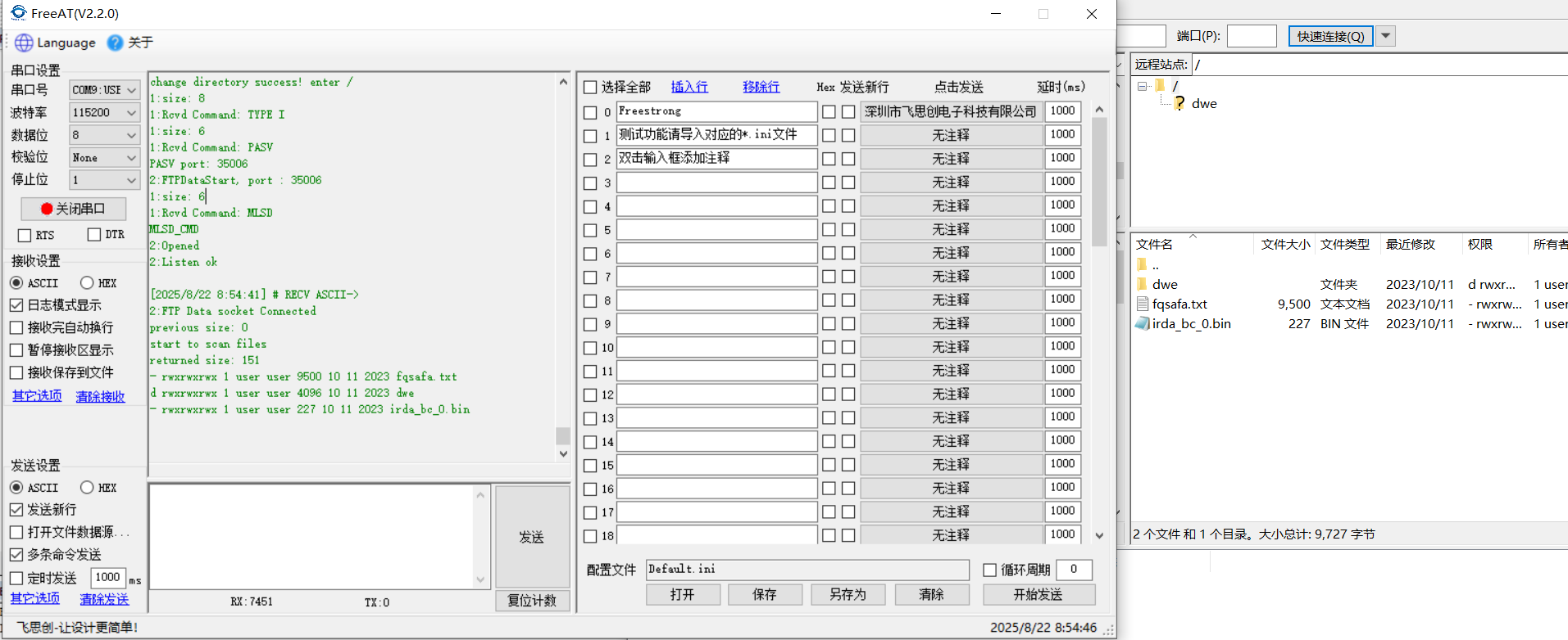
` }5.运行结果
目前的 FatFs 文件系统支持删除,上传服务器文件,也支持删除和上传目录。当前文件系统仅支持英文,如果需要支持中文,需要在 ffconf.h 中修改_CODE_PAGE 宏定义为 936 并使用 cc936.c 文件即可。
由于FatFs不支持访问权限这一功能,所以在代码中预定义了一个宏,将访问权限全部设为可读可写可执行,在客户端这边显示就是rwxrwxrwx。另外,当前不支持修改时间,如果需要,可在设备上电后访问sntp服务器,并启用RTC时钟即可。
客户端使用 filezilla 做测试,访问FileZilla - The free FTP solution下载。
目前我的文件系统有一些文件,当使用 filezilla 访问服务器时,会显示如下文件:
删除目录操作如下:
由于操作较多,其他操作就不演示了。可自行测试。
6.总结
本文详细介绍了如何利用 W55Mh32Q-EVB 实现 FTP 服务器,通过移植 FatFs 文件系统来存储文件,可用于存储日志信息等。感谢大家的耐心阅读!如果您在阅读过程中有任何疑问,或者希望进一步了解这款产品及其应用,欢迎随时通过私信或评论区留言。我们会尽快回复您的消息,为您提供更详细的解答和帮助!