一、项目要求
1、网络架构规划
(1)vlan和网段规划
- 某学院网络覆盖全校,包含教学区、行政办公区、服务器设备区、生活后勤区等。
- 总共有 20 个部门/功能区,每个部门独立 VLAN 和网段,统一管理 VLAN。
- 服务器区域与设备管理单独规划 VLAN,网段。
- 20个部门分别设置单独的VLAN,单独的网段做区分;
- 全网设备统一规划一个单独的管理VLAN,管理网段;
- 服务器区域和管理区域单独规划一个vlan和网段,网关设置在核心交换机上;
学校有20个部门,参见下表:
| 序号 | 部门**/区域名称** | VLAN ID | 地址段 | 网关地址 |
|---|---|---|---|---|
| 1 | 校长办公室 | 10 | 192.168.10.0/24 | 192.168.10.254/24 |
| 2 | 教务处 | 20 | 192.168.20.0/24 | 192.168.20.254/24 |
| 3 | 人事处 | 30 | 192.168.30.0/24 | 192.168.30.254/24 |
| 4 | 财务处 | 40 | 192.168.40.0/24 | 192.168.40.254/24 |
| 5 | 学生处 | 50 | 192.168.50.0/24 | 192.168.50.254/24 |
| 6 | 招生就业 | 60 | 192.168.60.0/24 | 192.168.60.254/24 |
| 7 | 总务处 | 70 | 192.168.70.0/24 | 192.168.70.254/24 |
| 8 | 信息中心 | 80 | 192.168.80.0/24 | 192.168.80.254/24 |
| 9 | 尚行楼 | 90 | 192.168.90.0/24 | 192.168.90.254/24 |
| 10 | 恒志楼 | 100 | 192.168.100.0/24 | 192.168.100.254/24 |
| 11 | 笃学楼 | 110 | 192.168.110.0/24 | 192.168.110.254/24 |
| 12 | 图书馆 | 120 | 192.168.120.0/24 | 192.168.120.254/24 |
| 13 | 实训中心 | 130 | 192.168.130.0/24 | 192.168.130.254/24 |
| 14 | 科研楼 | 140 | 192.168.140.0/24 | 192.168.140.254/24 |
| 15 | 体育馆 | 150 | 192.168.150.0/24 | 192.168.150.254/24 |
| 16 | 学生宿舍1 | 160 | 192.168.160.0/24 | 192.168.160.254/24 |
| 17 | 学生宿舍2 | 170 | 192.168.170.0/24 | 192.168.170.254/24 |
| 18 | 教工宿舍区 | 180 | 192.168.180.0/24 | 192.168.180.254/24 |
| 19 | 后勤保障中心 | 190 | 192.168.190.0/24 | 192.168.190.254/24 |
| 20 | 校医院 | 200 | 192.168.200.0/24 | 192.168.200.254/24 |
| 管理VLAN | 网络管理/设备管控 | 250 | 192.168.250.0/24 | 192.168.250.254/24 |
| 服务器区 | 校内业务系统服务器 | 220 | 192.168.220.0/24 | 192.168.220.254/24 |
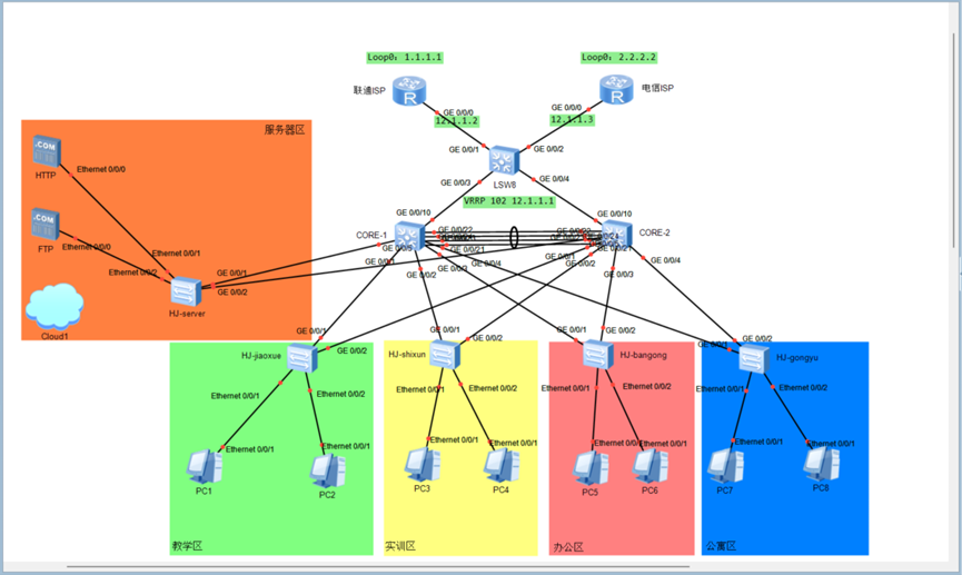
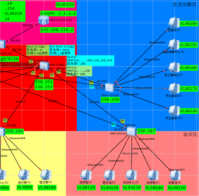
(2)网络结构优化
根据学校的规划建设需求,前期先行规划网络结构如下:
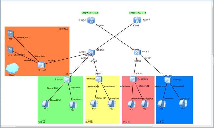
原先的网络拓扑,缺乏可靠性和可用性设计,容易出现单点故障和单链路故障,请你根据现行的优化网络拓扑设计,搭建网络环境。
(3)基本配置
- 根据上述拓扑图内容,对全网设备的命名等基本信息进行配置。
2、交换部分
(1)VLAN
- 为每个部门/区域配置独立 VLAN。
- 为管理 VLAN及服务器 VLAN单独进行配置。
- 所有行政部门PC的VLAN划分,配置基于MAC地址的VLAN划分,根据MAC地址自动匹配对应VLAN,实现行政部门在办公区任意接口都能分配到正确的VLAN中。
- 划分到独立vlan中,可以有效防止部门间的二层网络泛洪与窃听,即使在同一台交换机下,不同部门的流量在二层也是完全隔离的,构成了网络安全的屏障
- (MAC-VLAN)采用传统的基于端口的vlan,每次员工更换工位,都需要网络管理员重新配置该接入端口的vlan,工作量大且容易出错,用MAC-VLAN技术,无论员工将电脑连接到办公区内任何一个接入端口,交换机一旦识别到该MAC地址,就会自动将这个端口动态地划分到行政VLAN中,极大减轻了运维管理工作量,提升了用户体验和网络的灵活性,同时保持了访问权限一致性
(2)TRUNK
- 所有交换机互联链路启用 trunk 模式。
- Trunk接口用于跨交换机的vlan数据传输和通信
- trunk 链路仅允许 VLAN 信息表中列出的 VLAN ID 通过。
- 只允许信息表中列出的VLAN ID通过可以避免信息泄露或者VLAN跳跃攻击,减少不必要的广播、组播流量在骨干链路上泛洪,节约了带宽资源
- Trunk链路的放通,要考虑后续的MSTP实例和VRRP相关的规划。
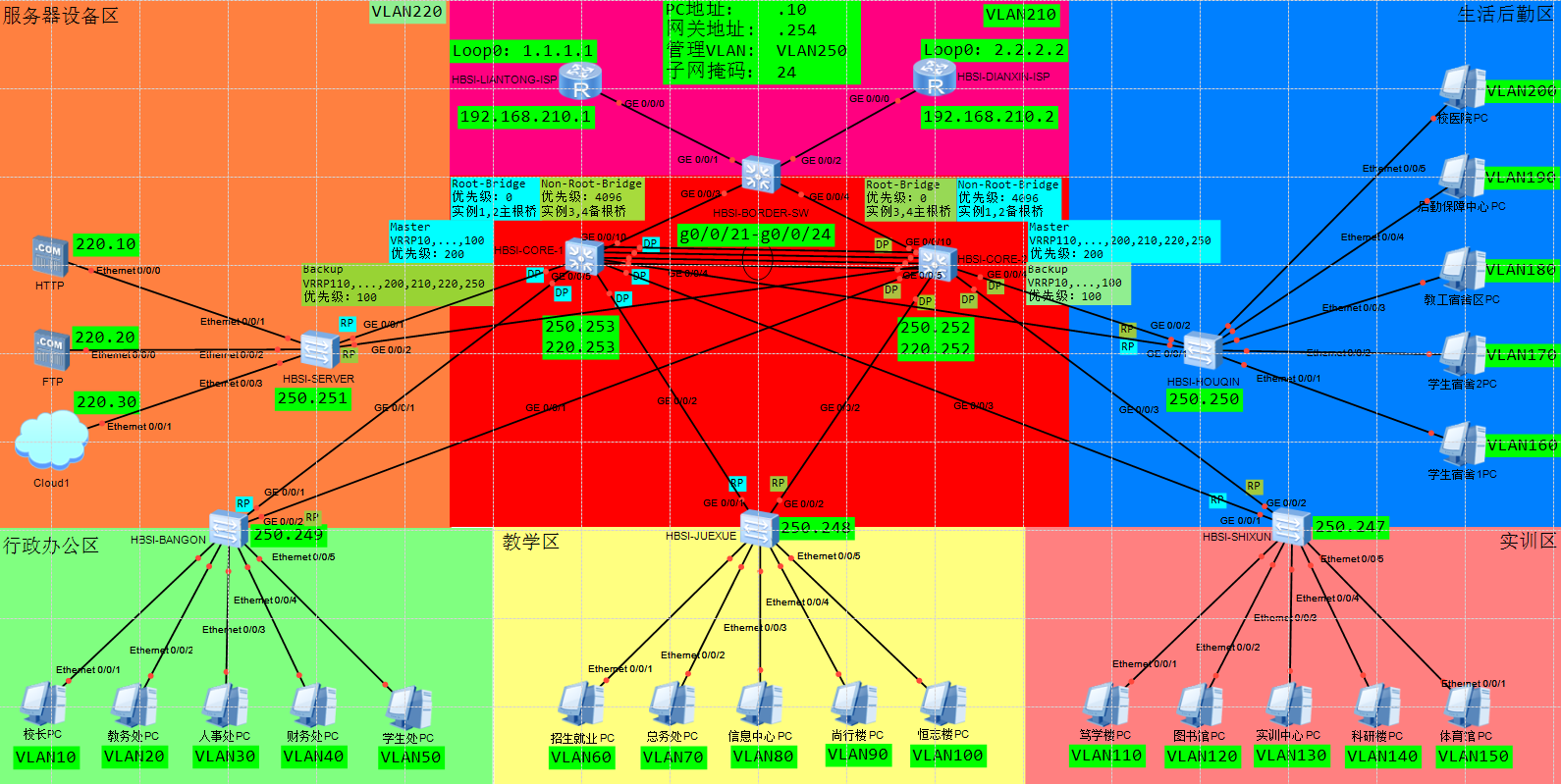
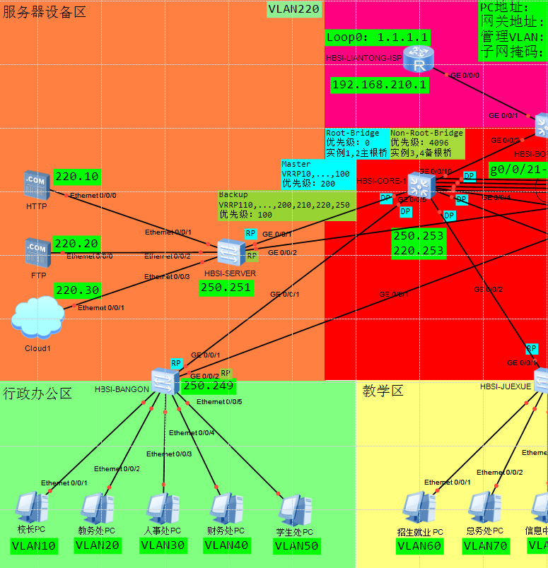
(3)STP
- STP采用MSTP模式,配合VRRP实现流量负载分担。
实例划分:
- Inst 1:行政办公类 VLAN
- Inst 2:教学类 VLAN
- Inst 3:实训类VLAN
- Inst 4:生活后勤类和特定业务类 VLAN
- 全域主根桥为核心1,副根桥为核心2。
- 实例1,2主根桥在核心1,实例3,4主根桥在核心2。
- 接入PC端口开启边缘端口;
- 接入PC端口开启BPDU防护;
(4)链路捆绑
- 两台核心交换机之间直连链路开启链路捆绑,流量负载均衡;
- 链路捆绑使用lacp协议,SW1优先级最高。
- 指定活动链路最大活动接口3个。
(5)三层交换
- 核心交换机启用vlanif接口,为各个用户vlan网段承担网关功能,并且实现交换网络内部三层通信。
(6)VRRP
- 在两台核心交换上开启VRRP,为业务网段提供网关冗余功能。
- 为连接运营商出口的两台路由器互联网段启用VRRP,提供下一跳冗余功能。
- 其中,核心交换机采用主备部署模式,CORE1和2的流量要负载分担;
- 实现当VRRP组的上行接口故障后,能够第一时间感知并切换主备角色,确保流量不中断。
(7)设备管理
- 在全网设备上配置telnet,使得位于服务器区域的设备可以远程telnet到任意一台设备上进行调试配置。
3、路由部分
(1)出网路由
- 两台核心交换机上通过配置出网路由,实现和internet(loop口模拟)互通。
(2)备份路由
- 实现当核心1或核心2交换机连接路由器的线路或接口单边失效以后,用户还能与外网进行通信。
(3)回程汇总路由
- 在ISP路由器上配置回程的汇总路由,要求做到主备负载分担。
4、攻防部分
(1)ARP攻击测试
- 服务器区域现有一台FTP服务器,请你对服务器区域的网络和设备进行测试,是否存在ARP攻击风险,并提出修复加固的具体措施。
(2)MAC泛洪攻击测试防御
- 服务器区域现有一台HTTP服务器,请你对服务器区域的网络和设备进行测试,是否存在MAC地址泛洪攻击风险,并提出修复加固的具体措施。
二、项目拓扑
三、项目配置
1、HBSI-BANGONG
# 关闭终端监控功能
undo terminal monitor

# 进入系统视图
system-view

# 设置设备名称为HBSI-BANGONG
sysname HBSI-BANGONG


# 批量创建VLAN 10,20,30,40,50,250
vlan batch 10 20 30 40 50 250

# 进入VLAN 10配置视图
vlan 10

# 配置MAC-VLAN,绑定MAC地址5489-98A8-422D到VLAN 10
mac-vlan mac-address 5489-98A8-422D

# 退出当前视图
quit

# 进入以太网接口0/0/1
interface Ethernet 0/0/1

# 设置接口链路类型为hybrid
port link-type hybrid

# 配置接口以untagged方式加入VLAN 10
port hybrid untagged vlan 10

# 启用MAC-VLAN功能
mac-vlan enable

# 启用端口安全功能
port-security enable

# 设置端口最大MAC地址学习数量为2
port-security max-mac-num 2

# 设置端口安全保护动作为restrict(限制)
port-security protect-action restrict

# 退出当前视图
quit

# 进入VLAN 20配置视图
vlan 20

# 配置MAC-VLAN,绑定MAC地址5489-9829-35A9到VLAN 20
mac-vlan mac-address 5489-9829-35A9

# 退出当前视图
quit

# 进入以太网接口0/0/2
interface Ethernet 0/0/2

# 设置接口链路类型为hybrid
port link-type hybrid

# 配置接口以untagged方式加入VLAN 20
port hybrid untagged vlan 20

# 启用MAC-VLAN功能
mac-vlan enable

# 启用端口安全功能
port-security enable

# 设置端口最大MAC地址学习数量为2
port-security max-mac-num 2

# 设置端口安全保护动作为restrict(限制)
port-security protect-action restrict

# 退出当前视图
quit

# 进入VLAN 30配置视图
vlan 30

# 配置MAC-VLAN,绑定MAC地址5489-98B7-4C14到VLAN 30
mac-vlan mac-address 5489-98B7-4C14

# 退出当前视图
quit

# 进入以太网接口0/0/3
interface Ethernet 0/0/3

# 设置接口链路类型为hybrid
port link-type hybrid

# 配置接口以untagged方式加入VLAN 30
port hybrid untagged vlan 30

# 启用MAC-VLAN功能
mac-vlan enable

# 启用端口安全功能
port-security enable

# 设置端口最大MAC地址学习数量为2
port-security max-mac-num 2

# 设置端口安全保护动作为restrict(限制)
port-security protect-action restrict

# 退出当前视图
quit

# 进入VLAN 40配置视图
vlan 40

# 配置MAC-VLAN,绑定MAC地址5489-987C-3805到VLAN 40
mac-vlan mac-address 5489-987C-3805

# 退出当前视图
quit

# 进入以太网接口0/0/4
interface Ethernet 0/0/4

# 设置接口链路类型为hybrid
port link-type hybrid

# 配置接口以untagged方式加入VLAN 40
port hybrid untagged vlan 40

# 启用MAC-VLAN功能
mac-vlan enable

# 启用端口安全功能
port-security enable

# 设置端口最大MAC地址学习数量为2
port-security max-mac-num 2

# 设置端口安全保护动作为restrict(限制)
port-security protect-action restrict

# 退出当前视图
quit

# 进入VLAN 50配置视图
vlan 50

# 配置MAC-VLAN,绑定MAC地址5489-9853-6315到VLAN 50
mac-vlan mac-address 5489-9853-6315

# 退出当前视图
quit

# 进入以太网接口0/0/5
interface Ethernet 0/0/5

# 设置接口链路类型为hybrid
port link-type hybrid

# 配置接口以untagged方式加入VLAN 50
port hybrid untagged vlan 50

# 启用MAC-VLAN功能
mac-vlan enable

# 启用端口安全功能
port-security enable

# 设置端口最大MAC地址学习数量为2
port-security max-mac-num 2

# 设置端口安全保护动作为restrict(限制)
port-security protect-action restrict

# 退出当前视图
quit

# 进入千兆以太网接口0/0/1
interface GigabitEthernet 0/0/1

# 设置接口链路类型为trunk
port link-type trunk

# 配置trunk接口允许通过的VLAN列表
port trunk allow-pass vlan 10 20 30 40 50 250

# 进入千兆以太网接口0/0/2
interface GigabitEthernet 0/0/2

# 设置接口链路类型为trunk
port link-type trunk

# 配置trunk接口允许通过的VLAN列表
port trunk allow-pass vlan 10 20 30 40 50 250

# 退出当前视图
quit


# 启用生成树协议
stp enable

# 设置生成树模式为MSTP
stp mode mstp

# 进入MSTP区域配置视图
stp region-configuration

# 设置MSTP区域名称为HBSI
region-name HBSI

# 配置实例1映射的VLAN
instance 1 vlan 10 20 30 40 50

# 配置实例2映射的VLAN
instance 2 vlan 60 70 80 90 100

# 配置实例3映射的VLAN
instance 3 vlan 110 120 130 140 150

# 配置实例4映射的VLAN
instance 4 vlan 160 170 180 190 200 210 220 250

# 激活MSTP区域配置
active region-configuration

# 退出当前视图
quit

# 启用BPDU保护功能
stp bpdu-protection

# 配置BPDU保护错误自动恢复,间隔30秒
error-down auto-recovery cause bpdu-protection interval 30

# 创建端口组,包含以太网接口0/0/1到0/0/5
port-group group-member Ethernet 0/0/1 to Ethernet 0/0/5

# 启用边缘端口功能
stp edged-port enable

# 退出当前视图
quit


# 进入VLANIF 250接口视图
interface Vlanif 250

# 配置VLANIF 250接口的IP地址和掩码
ip address 192.168.250.249 24


# 启用Telnet服务器功能
telnet server enable

# 进入AAA配置视图
aaa

# 创建本地用户admin并设置密码为huawei@123(密文)
local-user admin password cipher huawei@123

# 设置用户admin的权限级别为3
local-user admin privilege level 3

# 设置用户admin的服务类型为Telnet
local-user admin service-type telnet

# 退出当前视图
quit

# 进入VTY用户界面视图(0-4)
user-interface vty 0 4

# 设置认证模式为AAA
authentication-mode aaa

# 指定入向协议为Telnet
protocol inbound telnet

# 设置空闲超时时间为15分钟
idle-timeout 15 0

# 退出当前视图
quit

# 配置静态路由,目的网络192.168.220.0/24,出接口为Vlanif 250,下一跳为192.168.250.254
ip route-static 192.168.220.0 24 vlanif 250 192.168.250.254
2、HBSI-JUEXUE
# 关闭终端监控功能
undo terminal monitor

# 进入系统视图
system-view

# 设置设备名称为HBSI-JUEXUE
sysname HBSI-JUEXUE


# 批量创建VLAN 60,70,80,90,100,250
vlan batch 60 70 80 90 100 250

# 进入以太网接口0/0/1
interface Ethernet 0/0/1

# 设置接口链路类型为access
port link-type access

# 设置接口默认VLAN为60
port default vlan 60

# 进入以太网接口0/0/2
interface Ethernet 0/0/2

# 设置接口链路类型为access
port link-type access

# 设置接口默认VLAN为70
port default vlan 70

# 进入以太网接口0/0/3
interface Ethernet 0/0/3

# 设置接口链路类型为access
port link-type access

# 设置接口默认VLAN为80
port default vlan 80

# 进入以太网接口0/0/4
interface Ethernet 0/0/4

# 设置接口链路类型为access
port link-type access

# 设置接口默认VLAN为90
port default vlan 90

# 进入以太网接口0/0/5
interface Ethernet 0/0/5

# 设置接口链路类型为access
port link-type access

# 设置接口默认VLAN为100
port default vlan 100

# 进入千兆以太网接口0/0/1
interface GigabitEthernet 0/0/1

# 设置接口链路类型为trunk
port link-type trunk

# 配置trunk接口允许通过的VLAN列表
port trunk allow-pass vlan 60 70 80 90 100 250

# 进入千兆以太网接口0/0/2
interface GigabitEthernet 0/0/2

# 设置接口链路类型为trunk
port link-type trunk

# 配置trunk接口允许通过的VLAN列表
port trunk allow-pass vlan 60 70 80 90 100 250

# 退出当前视图
quit


# 设置生成树模式为MSTP
stp mode mstp

# 进入MSTP区域配置视图
stp region-configuration

# 设置MSTP区域名称为HBSI
region-name HBSI

# 配置实例1映射的VLAN
instance 1 vlan 10 20 30 40 50

# 配置实例2映射的VLAN
instance 2 vlan 60 70 80 90 100

# 配置实例3映射的VLAN
instance 3 vlan 110 120 130 140 150

# 配置实例4映射的VLAN
instance 4 vlan 160 170 180 190 200 210 220 250

# 激活MSTP区域配置
active region-configuration

# 退出当前视图
quit

# 启用BPDU保护功能
stp bpdu-protection

# 配置BPDU保护错误自动恢复,间隔30秒
error-down auto-recovery cause bpdu-protection interval 30

# 创建端口组,包含以太网接口0/0/1到0/0/5
port-group group-member Ethernet 0/0/1 to Ethernet 0/0/5

# 启用边缘端口功能
stp edged-port enable

# 退出当前视图
quit


# 进入VLANIF 250接口视图
interface Vlanif 250

# 配置VLANIF 250接口的IP地址和掩码
ip address 192.168.250.248 24


# 启用Telnet服务器功能
telnet server enable

# 进入AAA配置视图
aaa

# 创建本地用户admin并设置密码为huawei@123(密文)
local-user admin password cipher huawei@123

# 设置用户admin的权限级别为3
local-user admin privilege level 3

# 设置用户admin的服务类型为Telnet
local-user admin service-type telnet

# 退出当前视图
quit

# 进入VTY用户界面视图(0-4)
user-interface vty 0 4

# 设置认证模式为AAA
authentication-mode aaa

# 指定入向协议为Telnet
protocol inbound telnet

# 设置空闲超时时间为15分钟
idle-timeout 15 0

# 退出当前视图
quit


# 配置静态路由,目的网络192.168.220.0/24,出接口为Vlanif 250,下一跳为192.168.250.254
ip route-static 192.168.220.0 24 vlanif 250 192.168.250.254
3、HBSI-SHIXUN
# 关闭终端监控功能,停止在终端显示系统日志信息,使操作界面更清晰
undo terminal monitor

# 进入系统视图,开始进行系统级配置
system-view

# 设置设备名称为HBSI-SHIXUN,便于网络管理和识别
sysname HBSI-SHIXUN


# 批量创建VLAN 110,120,130,140,150,250
vlan batch 110 120 130 140 150 250

# 进入以太网接口0/0/1
interface Ethernet 0/0/1

# 设置接口链路类型为access,用于连接终端设备
port link-type access

# 设置接口默认VLAN为110,接口将加入VLAN 110
port default vlan 110

# 进入以太网接口0/0/2
interface Ethernet 0/0/2

# 设置接口链路类型为access,用于连接终端设备
port link-type access

# 设置接口默认VLAN为120,接口将加入VLAN 120
port default vlan 120

# 进入以太网接口0/0/3
interface Ethernet 0/0/3

# 设置接口链路类型为access,用于连接终端设备
port link-type access

# 设置接口默认VLAN为130,接口将加入VLAN 130
port default vlan 130

# 进入以太网接口0/0/4
interface Ethernet 0/0/4

# 设置接口链路类型为access,用于连接终端设备
port link-type access

# 设置接口默认VLAN为140,接口将加入VLAN 140
port default vlan 140

# 进入以太网接口0/0/5
interface Ethernet 0/0/5

# 设置接口链路类型为access,用于连接终端设备
port link-type access

# 设置接口默认VLAN为150,接口将加入VLAN 150
port default vlan 150

# 进入千兆以太网接口0/0/1
interface GigabitEthernet 0/0/1

# 设置接口链路类型为trunk,用于交换机间连接
port link-type trunk

# 配置trunk接口允许通过的VLAN列表
port trunk allow-pass vlan 110 120 130 140 150 250

# 进入千兆以太网接口0/0/2
interface GigabitEthernet 0/0/2

# 设置接口链路类型为trunk,用于交换机间连接
port link-type trunk

# 配置trunk接口允许通过的VLAN列表
port trunk allow-pass vlan 110 120 130 140 150 250

# 退出当前视图
quit


# 启用生成树协议,防止网络环路
stp enable

# 设置生成树模式为MSTP(多生成树协议)
stp mode mstp

# 进入MSTP区域配置视图
stp region-configuration

# 设置MSTP区域名称为HBSI
region-name HBSI

# 配置实例1映射的VLAN
instance 1 vlan 10 20 30 40 50

# 配置实例2映射的VLAN
instance 2 vlan 60 70 80 90 100

# 配置实例3映射的VLAN
instance 3 vlan 110 120 130 140 150

# 配置实例4映射的VLAN
instance 4 vlan 160 170 180 190 200 210 220 250

# 激活MSTP区域配置
active region-configuration

# 退出当前视图
quit

# 启用BPDU保护功能,防止非法设备影响生成树拓扑
stp bpdu-protection

# 配置BPDU保护错误自动恢复,间隔30秒
error-down auto-recovery cause bpdu-protection interval 30

# 创建端口组,包含以太网接口0/0/1到0/0/5
port-group group-member Ethernet 0/0/1 to Ethernet 0/0/5

# 启用边缘端口功能,这些端口连接终端设备,可快速进入转发状态
stp edged-port enable

# 退出当前视图
quit


# 进入VLANIF 250接口视图,创建三层虚拟接口
interface Vlanif 250

# 配置VLANIF 250接口的IP地址和掩码,用于三层通信
ip address 192.168.250.247 24


# 启用Telnet服务器功能,允许远程登录管理
telnet server enable

# 进入AAA配置视图,进行认证、授权和计费配置
aaa

# 创建本地用户admin并设置密码为huawei@123(密文存储)
local-user admin password cipher huawei@123

# 设置用户admin的权限级别为3(管理级权限)
local-user admin privilege level 3

# 设置用户admin的服务类型为Telnet
local-user admin service-type telnet

# 退出当前视图
quit

# 进入VTY用户界面视图(0-4),共5个虚拟终端连接
user-interface vty 0 4

# 设置认证模式为AAA,使用AAA视图中的用户信息进行认证
authentication-mode aaa

# 指定入向协议为Telnet,限制这些虚拟终端只用于Telnet连接
protocol inbound telnet

# 设置空闲超时时间为15分钟0秒,增强安全性
idle-timeout 15 0

# 退出当前视图
quit


# 配置静态路由,目的网络192.168.220.0/24,出接口为Vlanif 250,下一跳为192.168.250.254
ip route-static 192.168.220.0 24 vlanif 250 192.168.250.254
4、HBSI-HOUQIN
# 关闭终端监控功能,停止在终端显示系统日志信息,使操作界面更清晰
undo terminal monitor

# 进入系统视图,开始进行系统级配置
system-view

# 设置设备名称为HBSI-HOUQIN,便于网络管理和识别
sysname HBSI-HOUQIN


# 批量创建VLAN 160,170,180,190,200,250,提高配置效率
vlan batch 160 170 180 190 200 250

# 进入以太网接口0/0/1
interface Ethernet 0/0/1

# 设置接口链路类型为access,用于连接终端设备
port link-type access

# 设置接口默认VLAN为160,接口将加入VLAN 160
port default vlan 160

# 进入以太网接口0/0/2
interface Ethernet 0/0/2

# 设置接口链路类型为access,用于连接终端设备
port link-type access

# 设置接口默认VLAN为170,接口将加入VLAN 170
port default vlan 170

# 进入以太网接口0/0/3
interface Ethernet 0/0/3

# 设置接口链路类型为access,用于连接终端设备
port link-type access

# 设置接口默认VLAN为180,接口将加入VLAN 180
port default vlan 180

# 进入以太网接口0/0/4
interface Ethernet 0/0/4

# 设置接口链路类型为access,用于连接终端设备
port link-type access

# 设置接口默认VLAN为190,接口将加入VLAN 190
port default vlan 190

# 进入以太网接口0/0/5
interface Ethernet 0/0/5

# 设置接口链路类型为access,用于连接终端设备
port link-type access

# 设置接口默认VLAN为200,接口将加入VLAN 200
port default vlan 200

# 进入千兆以太网接口0/0/1
interface GigabitEthernet 0/0/1

# 设置接口链路类型为trunk,用于交换机间连接
port link-type trunk

# 配置trunk接口允许通过的VLAN列表
port trunk allow-pass vlan 160 170 180 190 200 250

# 进入千兆以太网接口0/0/2
interface GigabitEthernet 0/0/2

# 设置接口链路类型为trunk,用于交换机间连接
port link-type trunk

# 配置trunk接口允许通过的VLAN列表
port trunk allow-pass vlan 160 170 180 190 200 250

# 退出当前视图
quit


# 启用生成树协议,防止网络环路
stp enable

# 设置生成树模式为MSTP(多生成树协议)
stp mode mstp

# 进入MSTP区域配置视图
stp region-configuration

# 设置MSTP区域名称为HBSI
region-name HBSI

# 配置实例1映射的VLAN
instance 1 vlan 10 20 30 40 50

# 配置实例2映射的VLAN
instance 2 vlan 60 70 80 90 100

# 配置实例3映射的VLAN
instance 3 vlan 110 120 130 140 150

# 配置实例4映射的VLAN
instance 4 vlan 160 170 180 190 200 210 220 250

# 激活MSTP区域配置
active region-configuration

# 退出当前视图
quit

# 启用BPDU保护功能,防止非法设备影响生成树拓扑
stp bpdu-protection

# 配置BPDU保护错误自动恢复,间隔30秒
error-down auto-recovery cause bpdu-protection interval 30

# 创建端口组,包含以太网接口0/0/1到0/0/5
port-group group-member Ethernet 0/0/1 to Ethernet 0/0/5

# 启用边缘端口功能,这些端口连接终端设备,可快速进入转发状态
stp edged-port enable

# 退出当前视图
quit


# 进入VLANIF 250接口视图,创建三层虚拟接口
interface Vlanif 250

# 配置VLANIF 250接口的IP地址和掩码,用于三层通信
ip address 192.168.250.250 24


# 启用Telnet服务器功能,允许远程登录管理
telnet server enable

# 进入AAA配置视图,进行认证、授权和计费配置
aaa

# 创建本地用户admin并设置密码为huawei@123(密文存储)
local-user admin password cipher huawei@123

# 设置用户admin的权限级别为3(管理级权限)
local-user admin privilege level 3

# 设置用户admin的服务类型为Telnet
local-user admin service-type telnet

# 退出当前视图
quit

# 进入VTY用户界面视图(0-4),共5个虚拟终端连接
user-interface vty 0 4

# 设置认证模式为AAA,使用AAA视图中的用户信息进行认证
authentication-mode aaa

# 指定入向协议为Telnet,限制这些虚拟终端只用于Telnet连接
protocol inbound telnet

# 设置空闲超时时间为15分钟0秒,增强安全性
idle-timeout 15 0

# 退出当前视图
quit


# 配置静态路由,目的网络192.168.220.0/24,出接口为Vlanif 250,下一跳为192.168.250.254
ip route-static 192.168.220.0 24 vlanif 250 192.168.250.254
5、HBSI-SERVER
# 关闭终端监控功能,停止在终端显示系统日志、调试等信息,使操作界面更清晰
undo terminal monitor

# 进入系统视图,开始进行系统级配置
system-view

# 设置设备名称为HBSI-HBSI-SERVER
sysname HBSI-HBSI-SERVER


# 批量创建VLAN 220和250
vlan batch 220 250

# 进入以太网接口0/0/1
interface Ethernet 0/0/1

# 设置接口链路类型为access,用于连接终端设备
port link-type access

# 设置接口默认VLAN为220,接口将加入VLAN 220
port default vlan 220

# 启用边缘端口功能,这些端口连接终端设备,可快速进入转发状态
stp edged-port enable

# 启用BPDU过滤功能,边缘端口不发送BPDU
stp bpdu-filter enable

# 启用端口安全功能
port-security enable

# 设置端口最大MAC地址学习数量为2
port-security max-mac-num 2

# 设置端口安全保护动作为shutdown(违反时关闭端口)
port-security protect-action shutdown

# 启用粘性MAC功能,动态学习到的MAC会转换为粘性MAC
port-security mac-address sticky

# 启用ARP防攻击限速,限制ARP报文率为10
arp anti-attack rate-limit 10

# 进入以太网接口0/0/2
interface Ethernet 0/0/2

# 设置接口链路类型为access,用于连接终端设备
port link-type access

# 设置接口默认VLAN为220,接口将加入VLAN 220
port default vlan 220

# 启用边缘端口功能,这些端口连接终端设备,可快速进入转发状态
stp edged-port enable

# 启用BPDU过滤功能,边缘端口不发送BPDU
stp bpdu-filter enable

# 启用端口安全功能
port-security enable

# 设置端口最大MAC地址学习数量为2
port-security max-mac-num 2

# 设置端口安全保护动作为shutdown(违反时关闭端口)
port-security protect-action shutdown

# 启用粘性MAC功能,动态学习到的MAC会转换为粘性MAC
port-security mac-address sticky

# 启用ARP防攻击限速,限制ARP报文率为10
arp anti-attack rate-limit 10

# 进入以太网接口0/0/3
interface Ethernet 0/0/3

# 设置接口链路类型为access,用于连接终端设备
port link-type access

# 设置接口默认VLAN为220,接口将加入VLAN 220
port default vlan 220

# 启用边缘端口功能,这些端口连接终端设备,可快速进入转发状态
stp edged-port enable

# 启用BPDU过滤功能,边缘端口不发送BPDU
stp bpdu-filter enable

# 启用端口安全功能
port-security enable

# 设置端口最大MAC地址学习数量为2
port-security max-mac-num 2

# 设置端口安全保护动作为shutdown(违反时关闭端口)
port-security protect-action shutdown

# 启用粘性MAC功能,动态学习到的MAC会转换为粘性MAC
port-security mac-address sticky

# 启用ARP防攻击限速,限制ARP报文率为10
arp anti-attack rate-limit 10

# 进入千兆以太网接口0/0/1
interface GigabitEthernet 0/0/1

# 设置接口链路类型为trunk,用于交换机间连接
port link-type trunk

# 配置trunk接口允许通过的VLAN列表
port trunk allow-pass vlan 220 250

# 进入千兆以太网接口0/0/2
interface GigabitEthernet 0/0/2

# 设置接口链路类型为trunk,用于交换机间连接
port link-type trunk

# 配置trunk接口允许通过的VLAN列表
port trunk allow-pass vlan 220 250

# 退出当前视图
quit


# 启用生成树协议,防止网络环路
stp enable

# 设置生成树模式为MSTP(多生成树协议)
stp mode mstp

# 进入MSTP区域配置视图
stp region-configuration

# 设置MSTP区域名称为HBSI
region-name HBSI

# 配置实例1映射的VLAN
instance 1 vlan 10 20 30 40 50

# 配置实例2映射的VLAN
instance 2 vlan 60 70 80 90 100

# 配置实例3映射的VLAN
instance 3 vlan 110 120 130 140 150

# 配置实例4映射的VLAN
instance 4 vlan 160 170 180 190 200 210 220 250

# 激活MSTP区域配置
active region-configuration

# 退出当前视图
quit

# 启用BPDU保护功能,防止非法设备影响生成树拓扑
stp bpdu-protection

# 配置BPDU保护错误自动恢复,间隔30秒
error-down auto-recovery cause bpdu-protection interval 30

# 创建端口组,包含以太网接口0/0/1到0/0/3
port-group group-member Ethernet 0/0/1 to Ethernet 0/0/3

# 启用边缘端口功能,这些端口连接终端设备,可快速进入转发状态
stp edged-port enable

# 退出当前视图
quit


# 进入VLANIF 250接口视图,创建三层虚拟接口
interface Vlanif 250

# 配置VLANIF 250接口的IP地址和掩码,用于三层通信
ip address 192.168.250.251 24

# 进入VLANIF 220接口视图,创建三层虚拟接口
interface Vlanif 220

# 配置VLANIF 220接口的IP地址和掩码,用于三层通信
ip address 192.168.220.251 24


# 启用Telnet服务器功能,允许远程登录管理
telnet server enable

# 进入AAA配置视图,进行认证、授权和计费配置
aaa

# 创建本地用户admin并设置密码为huawei@123(密文存储)
local-user admin password cipher huawei@123

# 设置用户admin的权限级别为3(管理级权限)
local-user admin privilege level 3

# 设置用户admin的服务类型为Telnet
local-user admin service-type telnet

# 退出当前视图
quit

# 进入VTY用户界面视图(0-4),共5个虚拟终端连接
user-interface vty 0 4

# 设置认证模式为AAA,使用AAA视图中的用户信息进行认证
authentication-mode aaa

# 指定入向协议为Telnet,限制这些虚拟终端只用于Telnet连接
protocol inbound telnet

# 设置空闲超时时间为15分钟0秒,增强安全性
idle-timeout 15 0

# 退出当前视图
quit
6、HBSI-CORE1
# 关闭终端监控功能,停止在终端显示系统日志信息
undo terminal monitor

# 进入系统视图,开始进行系统级配置
system-view

# 设置设备名称为HBSI-CORE1,标识为核心交换机1
sysname HBSI-CORE1


# 批量创建VLAN 10-90,分三批创建以提高效率
vlan batch 10 20 30 40 50 60 70 80 90

# 批量创建VLAN 100-190
vlan batch 100 110 120 130 140 150 160 170 180 190

# 批量创建VLAN 200,210,220,250
vlan batch 200 210 220 250

# 进入千兆以太网接口0/0/1
interface GigabitEthernet 0/0/1

# 设置接口链路类型为trunk,用于交换机间连接
port link-type trunk

# 配置trunk接口允许通过的VLAN列表
port trunk allow-pass vlan 10 20 30 40 50 250

# 进入千兆以太网接口0/0/2
interface GigabitEthernet 0/0/2

# 设置接口链路类型为trunk,用于交换机间连接
port link-type trunk

# 配置trunk接口允许通过的VLAN列表
port trunk allow-pass vlan 60 70 80 90 100 250

# 进入千兆以太网接口0/0/3
interface GigabitEthernet 0/0/3

# 设置接口链路类型为trunk,用于交换机间连接
port link-type trunk

# 配置trunk接口允许通过的VLAN列表
port trunk allow-pass vlan 110 120 130 140 150 250

# 进入千兆以太网接口0/0/4
interface GigabitEthernet 0/0/4

# 设置接口链路类型为trunk,用于交换机间连接
port link-type trunk

# 配置trunk接口允许通过的VLAN列表
port trunk allow-pass vlan 160 170 180 190 200 250

# 进入千兆以太网接口0/0/5
interface GigabitEthernet 0/0/5

# 设置接口链路类型为trunk,用于交换机间连接
port link-type trunk

# 配置trunk接口允许通过的VLAN列表
port trunk allow-pass vlan 220 250

# 进入千兆以太网接口0/0/10
interface GigabitEthernet 0/0/10

# 设置接口链路类型为trunk,用于交换机间连接
port link-type trunk

# 配置trunk接口允许通过的VLAN列表
port trunk allow-pass vlan 210

# 退出当前视图
quit


# 启用生成树协议,防止网络环路
stp enable

# 设置生成树模式为MSTP(多生成树协议)
stp mode mstp

# 进入MSTP区域配置视图
stp region-configuration

# 设置MSTP区域名称为HBSI
region-name HBSI

# 配置实例1映射的VLAN
instance 1 vlan 10 20 30 40 50

# 配置实例2映射的VLAN
instance 2 vlan 60 70 80 90 100

# 配置实例3映射的VLAN
instance 3 vlan 110 120 130 140 150

# 配置实例4映射的VLAN
instance 4 vlan 160 170 180 190 200 210 220 250

# 激活MSTP区域配置
active region-configuration

# 退出当前视图
quit

# 设置生成树优先级为0(最高优先级,成为根桥)
stp priority 0

# 设置实例1的主根桥
stp instance 1 root primary

# 设置实例2的主根桥
stp instance 2 root primary

# 设置实例3的备根桥
stp instance 3 root secondary

# 设置实例4的备根桥
stp instance 4 root secondary


# 设置LACP系统优先级为100(数值越小优先级越高)
lacp priority 100

# 进入Eth-Trunk 1接口视图
interface Eth-Trunk 1

# 设置Eth-Trunk工作模式为LACP静态模式
mode lacp-static

# 启用LACP抢占功能
lacp preempt enable

# 设置LACP抢占延迟时间为30秒
lacp preempt delay 30

# 设置负载均衡模式为基于源目的IP地址
load-balance src-dst-ip

# 设置最大活动链路数量为3条
max active-linknumber 3

# 将物理接口G0/0/21加入Eth-Trunk 1
trunkport GigabitEthernet 0/0/21

# 将物理接口G0/0/22加入Eth-Trunk 1
trunkport GigabitEthernet 0/0/22

# 将物理接口G0/0/23加入Eth-Trunk 1
trunkport GigabitEthernet 0/0/23

# 将物理接口G0/0/24加入Eth-Trunk 1
trunkport GigabitEthernet 0/0/24

# 设置Eth-Trunk接口链路类型为trunk
port link-type trunk

# 配置Eth-Trunk允许通过的VLAN列表(第一部分)
port trunk allow-pass vlan 10 20 30 40 50 60 70 80 90

# 配置Eth-Trunk允许通过的VLAN列表(第二部分)
port trunk allow-pass vlan 100 110 120 130 140 150 160 170 180 190

# 配置Eth-Trunk允许通过的VLAN列表(第三部分)
port trunk allow-pass vlan 200 210 220 250

# 退出当前视图
quit


# 进入VLAN接口10的配置视图
interface Vlanif 10

# 配置VLAN接口10的IP地址为192.168.10.253,子网掩码为255.255.255.0
ip address 192.168.10.253 24

# 创建VRRP备份组10,并设置虚拟网关IP地址
vrrp vrid 10 virtual-ip 192.168.10.254

# 设置此设备在VRRP备份组10中的优先级为200(最高优先级,默认值为100)
vrrp vrid 10 priority 200

# 启用抢占模式并设置抢占延迟时间为5秒
vrrp vrid 10 preempt-mode timer delay 5

# 配置接口跟踪功能,监控GigabitEthernet0/0/10接口状态,如果该接口失效,优先级降低150
vrrp vrid 10 track interface GigabitEthernet0/0/10 reduced 150

# 进入VLAN接口20的配置视图
interface Vlanif 20

# 配置VLAN接口20的IP地址为192.168.20.253,子网掩码为255.255.255.0
ip address 192.168.20.253 24

# 创建VRRP备份组20,并设置虚拟网关IP地址
vrrp vrid 20 virtual-ip 192.168.20.254

# 设置此设备在VRRP备份组20中的优先级为200(最高优先级,默认值为100)
vrrp vrid 20 priority 200

# 启用抢占模式并设置抢占延迟时间为5秒
vrrp vrid 20 preempt-mode timer delay 5

# 配置接口跟踪功能,监控GigabitEthernet0/0/10接口状态,如果该接口失效,优先级降低150
vrrp vrid 20 track interface GigabitEthernet0/0/10 reduced 150

# 进入VLAN接口30的配置视图
interface Vlanif 30

# 配置VLAN接口30的IP地址为192.168.30.253,子网掩码为255.255.255.0
ip address 192.168.30.253 24

# 创建VRRP备份组30,并设置虚拟网关IP地址
vrrp vrid 30 virtual-ip 192.168.30.254

# 设置此设备在VRRP备份组30中的优先级为200(最高优先级,默认值为100)
vrrp vrid 30 priority 200

# 启用抢占模式并设置抢占延迟时间为5秒
vrrp vrid 30 preempt-mode timer delay 5

# 配置接口跟踪功能,监控GigabitEthernet0/0/10接口状态,如果该接口失效,优先级降低150
vrrp vrid 30 track interface GigabitEthernet0/0/10 reduced 150

# 进入VLAN接口40的配置视图
interface Vlanif 40

# 配置VLAN接口40的IP地址为192.168.40.253,子网掩码为255.255.255.0
ip address 192.168.40.253 24

# 创建VRRP备份组40,并设置虚拟网关IP地址
vrrp vrid 40 virtual-ip 192.168.40.254

# 设置此设备在VRRP备份组40中的优先级为200(最高优先级,默认值为100)
vrrp vrid 40 priority 200

# 启用抢占模式并设置抢占延迟时间为5秒
vrrp vrid 40 preempt-mode timer delay 5

# 配置接口跟踪功能,监控GigabitEthernet0/0/10接口状态,如果该接口失效,优先级降低150
vrrp vrid 40 track interface GigabitEthernet0/0/10 reduced 150

# 进入VLAN接口50的配置视图
interface Vlanif 50

# 配置VLAN接口50的IP地址为192.168.50.253,子网掩码为255.255.255.0
ip address 192.168.50.253 24

# 创建VRRP备份组50,并设置虚拟网关IP地址
vrrp vrid 50 virtual-ip 192.168.50.254

# 设置此设备在VRRP备份组50中的优先级为200(最高优先级,默认值为100)
vrrp vrid 50 priority 200

# 启用抢占模式并设置抢占延迟时间为5秒
vrrp vrid 50 preempt-mode timer delay 5

# 配置接口跟踪功能,监控GigabitEthernet0/0/10接口状态,如果该接口失效,优先级降低150
vrrp vrid 50 track interface GigabitEthernet0/0/10 reduced 150

# 进入VLAN接口60的配置视图
interface Vlanif 60

# 配置VLAN接口60的IP地址为192.168.60.253,子网掩码为255.255.255.0
ip address 192.168.60.253 24

# 创建VRRP备份组60,并设置虚拟网关IP地址
vrrp vrid 60 virtual-ip 192.168.60.254

# 设置此设备在VRRP备份组60中的优先级为200(最高优先级,默认值为100)
vrrp vrid 60 priority 200

# 启用抢占模式并设置抢占延迟时间为5秒
vrrp vrid 60 preempt-mode timer delay 5

# 配置接口跟踪功能,监控GigabitEthernet0/0/10接口状态,如果该接口失效,优先级降低150
vrrp vrid 60 track interface GigabitEthernet0/0/10 reduced 150

# 进入VLAN接口70的配置视图
interface Vlanif 70

# 配置VLAN接口70的IP地址为192.168.70.253,子网掩码为255.255.255.0
ip address 192.168.70.253 24

# 创建VRRP备份组70,并设置虚拟网关IP地址
vrrp vrid 70 virtual-ip 192.168.70.254

# 设置此设备在VRRP备份组70中的优先级为200(最高优先级,默认值为100)
vrrp vrid 70 priority 200

# 启用抢占模式并设置抢占延迟时间为5秒
vrrp vrid 70 preempt-mode timer delay 5

# 配置接口跟踪功能,监控GigabitEthernet0/0/10接口状态,如果该接口失效,优先级降低150
vrrp vrid 70 track interface GigabitEthernet0/0/10 reduced 150

# 进入VLAN接口80的配置视图
interface Vlanif 80

# 配置VLAN接口80的IP地址为192.168.80.253,子网掩码为255.255.255.0
ip address 192.168.80.253 24

# 创建VRRP备份组80,并设置虚拟网关IP地址
vrrp vrid 80 virtual-ip 192.168.80.254

# 设置此设备在VRRP备份组80中的优先级为200(最高优先级,默认值为100)
vrrp vrid 80 priority 200

# 启用抢占模式并设置抢占延迟时间为5秒
vrrp vrid 80 preempt-mode timer delay 5

# 配置接口跟踪功能,监控GigabitEthernet0/0/10接口状态,如果该接口失效,优先级降低150
vrrp vrid 80 track interface GigabitEthernet0/0/10 reduced 150

# 进入VLAN接口90的配置视图
interface Vlanif 90

# 配置VLAN接口90的IP地址为192.168.90.253,子网掩码为255.255.255.0
ip address 192.168.90.253 24

# 创建VRRP备份组90,并设置虚拟网关IP地址
vrrp vrid 90 virtual-ip 192.168.90.254

# 设置此设备在VRRP备份组90中的优先级为200(最高优先级,默认值为100)
vrrp vrid 90 priority 200

# 启用抢占模式并设置抢占延迟时间为5秒
vrrp vrid 90 preempt-mode timer delay 5

# 配置接口跟踪功能,监控GigabitEthernet0/0/10接口状态,如果该接口失效,优先级降低150
vrrp vrid 90 track interface GigabitEthernet0/0/10 reduced 150

# 进入VLAN接口100的配置视图
interface Vlanif 100

# 配置VLAN接口100的IP地址为192.168.100.253,子网掩码为255.255.255.0
ip address 192.168.100.253 24

# 创建VRRP备份组100,并设置虚拟网关IP地址
vrrp vrid 100 virtual-ip 192.168.100.254

# 设置此设备在VRRP备份组100中的优先级为200(最高优先级,默认值为100)
vrrp vrid 100 priority 200

# 启用抢占模式并设置抢占延迟时间为5秒
vrrp vrid 100 preempt-mode timer delay 5

# 配置接口跟踪功能,监控GigabitEthernet0/0/10接口状态,如果该接口失效,优先级降低150
vrrp vrid 100 track interface GigabitEthernet0/0/10 reduced 150

# 进入VLAN接口110的配置视图
interface Vlanif 110

# 配置VLAN接口110的IP地址为192.168.110.253,子网掩码为255.255.255.0
ip address 192.168.110.253 24

# 创建VRRP备份组110,并设置虚拟网关IP地址
vrrp vrid 110 virtual-ip 192.168.110.254

# 启用抢占模式并设置抢占延迟时间为0秒(立即抢占)
vrrp vrid 110 preempt-mode timer delay 0

# 进入VLAN接口120的配置视图
interface Vlanif 120

# 配置VLAN接口120的IP地址为192.168.120.253,子网掩码为255.255.255.0
ip address 192.168.120.253 24

# 创建VRRP备份组120,并设置虚拟网关IP地址
vrrp vrid 120 virtual-ip 192.168.120.254

# 启用抢占模式并设置抢占延迟时间为0秒(立即抢占)
vrrp vrid 120 preempt-mode timer delay 0

# 进入VLAN接口130的配置视图
interface Vlanif 130

# 配置VLAN接口130的IP地址为192.168.130.253,子网掩码为255.255.255.0
ip address 192.168.130.253 24

# 创建VRRP备份组130,并设置虚拟网关IP地址
vrrp vrid 130 virtual-ip 192.168.130.254

# 启用抢占模式并设置抢占延迟时间为0秒(立即抢占)
vrrp vrid 130 preempt-mode timer delay 0

# 进入VLAN接口140的配置视图
interface Vlanif 140

# 配置VLAN接口140的IP地址为192.168.140.253,子网掩码为255.255.255.0
ip address 192.168.140.253 24

# 创建VRRP备份组140,并设置虚拟网关IP地址
vrrp vrid 140 virtual-ip 192.168.140.254

# 启用抢占模式并设置抢占延迟时间为0秒(立即抢占)
vrrp vrid 140 preempt-mode timer delay 0

# 进入VLAN接口150的配置视图
interface Vlanif 150

# 配置VLAN接口150的IP地址为192.168.150.253,子网掩码为255.255.255.0
ip address 192.168.150.253 24

# 创建VRRP备份组150,并设置虚拟网关IP地址
vrrp vrid 150 virtual-ip 192.168.150.254

# 启用抢占模式并设置抢占延迟时间为0秒(立即抢占)
vrrp vrid 150 preempt-mode timer delay 0

# 进入VLAN接口160的配置视图
interface Vlanif 160

# 配置VLAN接口160的IP地址为192.168.160.253,子网掩码为255.255.255.0
ip address 192.168.160.253 24

# 创建VRRP备份组160,并设置虚拟网关IP地址
vrrp vrid 160 virtual-ip 192.168.160.254

# 启用抢占模式并设置抢占延迟时间为0秒(立即抢占)
vrrp vrid 160 preempt-mode timer delay 0

# 进入VLAN接口170的配置视图
interface Vlanif 170

# 配置VLAN接口170的IP地址为192.168.170.253,子网掩码为255.255.255.0
ip address 192.168.170.253 24

# 创建VRRP备份组170,并设置虚拟网关IP地址
vrrp vrid 170 virtual-ip 192.168.170.254

# 启用抢占模式并设置抢占延迟时间为0秒(立即抢占)
vrrp vrid 170 preempt-mode timer delay 0

# 进入VLAN接口180的配置视图
interface Vlanif 180

# 配置VLAN接口180的IP地址为192.168.180.253,子网掩码为255.255.255.0
ip address 192.168.180.253 24

# 创建VRRP备份组180,并设置虚拟网关IP地址
vrrp vrid 180 virtual-ip 192.168.180.254

# 启用抢占模式并设置抢占延迟时间为0秒(立即抢占)
vrrp vrid 180 preempt-mode timer delay 0

# 进入VLAN接口190的配置视图
interface Vlanif 190

# 配置VLAN接口190的IP地址为192.168.190.253,子网掩码为255.255.255.0
ip address 192.168.190.253 24

# 创建VRRP备份组190,并设置虚拟网关IP地址
vrrp vrid 190 virtual-ip 192.168.190.254

# 启用抢占模式并设置抢占延迟时间为0秒(立即抢占)
vrrp vrid 190 preempt-mode timer delay 0

# 进入VLAN接口200的配置视图
interface Vlanif 200

# 配置VLAN接口200的IP地址为192.168.200.253,子网掩码为255.255.255.0
ip address 192.168.200.253 24

# 创建VRRP备份组200,并设置虚拟网关IP地址
vrrp vrid 200 virtual-ip 192.168.200.254

# 启用抢占模式并设置抢占延迟时间为0秒(立即抢占)
vrrp vrid 200 preempt-mode timer delay 0

# 进入VLAN接口210的配置视图
interface Vlanif 210

# 配置VLAN接口210的IP地址为192.168.210.253,子网掩码为255.255.255.0
ip address 192.168.210.253 24

# 创建VRRP备份组210,并设置虚拟网关IP地址
vrrp vrid 210 virtual-ip 192.168.210.254

# 启用抢占模式并设置抢占延迟时间为0秒(立即抢占)
vrrp vrid 210 preempt-mode timer delay 0

# 进入VLAN接口220的配置视图
interface Vlanif 220

# 配置VLAN接口220的IP地址为192.168.220.253,子网掩码为255.255.255.0
ip address 192.168.220.253 24

# 创建VRRP备份组220,并设置虚拟网关IP地址
vrrp vrid 220 virtual-ip 192.168.220.254

# 启用抢占模式并设置抢占延迟时间为0秒(立即抢占)
vrrp vrid 220 preempt-mode timer delay 0

# 进入VLAN接口250的配置视图
interface Vlanif 250

# 配置VLAN接口250的IP地址为192.168.250.253,子网掩码为255.255.255.0
ip address 192.168.250.253 24

# 创建VRRP备份组250,并设置虚拟网关IP地址
vrrp vrid 250 virtual-ip 192.168.250.254

# 启用抢占模式并设置抢占延迟时间为0秒(立即抢占)
vrrp vrid 250 preempt-mode timer delay 0

# 退出当前接口配置视图
quit


# 启用Telnet服务器功能,允许设备接受Telnet连接
telnet server enable

# 进入AAA配置视图,进行认证、授权和计费配置
aaa

# 创建本地用户"admin",并设置密码为"huawei@123"(使用cipher可逆加密方式存储)
local-user admin password cipher huawei@123

# 设置用户"admin"的权限等级为3(管理级权限,可执行所有配置命令)
local-user admin privilege level 3

# 指定用户"admin"的服务类型为Telnet,允许该用户通过Telnet登录设备
local-user admin service-type telnet

# 退出AAA视图,返回系统视图
quit

# 进入虚拟终端线路视图(VTY 0到4),共5个虚拟终端连接
user-interface vty 0 4

# 设置VTY用户界面的认证模式为AAA认证,需输入用户名和密码
authentication-mode aaa

# 指定VTY用户界面支持的入向协议为Telnet
protocol inbound telnet

# 设置VTY用户界面的空闲超时时间为15分钟0秒,增强连接安全性
idle-timeout 15 0

# 退出VTY用户界面视图,返回系统视图
quit


# 配置静态路由,目的网段为1.1.1.0/24,下一跳地址为192.168.210.1
ip route-static 1.1.1.0 24 192.168.210.1

# 配置静态路由,目的网段为2.2.2.0/24,下一跳地址为192.168.210.2
ip route-static 2.2.2.0 24 192.168.210.2
7、HBSI-CORE2
# 关闭当前终端对系统信息、日志和调试信息的监视功能,使操作界面更简洁
undo terminal monitor

# 进入系统视图,开始进行系统级配置
system-view

# 设置设备名称为HBSI-CORE2,用于在网络中标识此设备
sysname HBSI-CORE2


# 批量创建VLAN 10至90,提高配置效率
vlan batch 10 20 30 40 50 60 70 80 90

# 批量创建VLAN 100至190
vlan batch 100 110 120 130 140 150 160 170 180 190

# 批量创建VLAN 200, 210, 220, 250
vlan batch 200 210 220 250

# 进入千兆以太网接口0/0/1的配置视图
interface GigabitEthernet 0/0/1

# 设置接口的链路类型为Trunk,用于承载多个VLAN的流量
port link-type trunk

# 配置Trunk接口允许通过的VLAN列表
port trunk allow-pass vlan 10 20 30 40 50 250

# 进入千兆以太网接口0/0/2的配置视图
interface GigabitEthernet 0/0/2

# 设置接口的链路类型为Trunk,用于承载多个VLAN的流量
port link-type trunk

# 配置Trunk接口允许通过的VLAN列表
port trunk allow-pass vlan 60 70 80 90 100 250

# 进入千兆以太网接口0/0/3的配置视图
interface GigabitEthernet 0/0/3

# 设置接口的链路类型为Trunk,用于承载多个VLAN的流量
port link-type trunk

# 配置Trunk接口允许通过的VLAN列表
port trunk allow-pass vlan 110 120 130 140 150 250

# 进入千兆以太网接口0/0/4的配置视图
interface GigabitEthernet 0/0/4

# 设置接口的链路类型为Trunk,用于承载多个VLAN的流量
port link-type trunk

# 配置Trunk接口允许通过的VLAN列表
port trunk allow-pass vlan 160 170 180 190 200 250

# 进入千兆以太网接口0/0/5的配置视图
interface GigabitEthernet 0/0/5

# 设置接口的链路类型为Trunk,用于承载多个VLAN的流量
port link-type trunk

# 配置Trunk接口允许通过的VLAN列表
port trunk allow-pass vlan 220 250

# 进入千兆以太网接口0/0/10的配置视图
interface GigabitEthernet 0/0/10

# 设置接口的链路类型为Trunk,用于承载多个VLAN的流量
port link-type trunk

# 配置Trunk接口允许通过的VLAN列表
port trunk allow-pass vlan 210

# 退出当前接口视图,返回系统视图
quit


# 启用生成树协议,防止网络中出现环路
stp enable

# 设置生成树模式为MSTP(多生成树协议)
stp mode mstp

# 进入MSTP区域配置视图
stp region-configuration

# 设置MSTP区域名称为HBSI
region-name HBSI

# 配置实例1与VLAN的映射关系
instance 1 vlan 10 20 30 40 50

# 配置实例2与VLAN的映射关系
instance 2 vlan 60 70 80 90 100

# 配置实例3与VLAN的映射关系
instance 3 vlan 110 120 130 140 150

# 配置实例4与VLAN的映射关系
instance 4 vlan 160 170 180 190 200 210 220 250

# 激活MSTP区域配置
active region-configuration

# 退出MSTP区域配置视图
quit

# 设置本设备在MSTP中的优先级为4096
stp priority 4096

# 设置本设备在实例1中作为备用根桥
stp instance 1 root secondary

# 设置本设备在实例2中作为备用根桥
stp instance 2 root secondary

# 设置本设备在实例3中作为主根桥
stp instance 3 root primary

# 设置本设备在实例4中作为主根桥
stp instance 4 root primary


# 设置LACP系统优先级为1000(数值越小优先级越高)
lacp priority 1000

# 进入Eth-Trunk 1接口视图
interface Eth-trunk 1

# 设置Eth-Trunk工作模式为LACP静态模式
mode lacp-static

# 启用LACP抢占功能
lacp preempt enable

# 设置LACP抢占延迟时间为30秒
lacp preempt delay 30

# 设置负载均衡模式为基于源目的IP地址
load-balance src-dst-ip

# 设置最大活动链路数量为3条
max active-linknumber 3

# 将物理接口G0/0/21加入Eth-Trunk 1
trunkport GigabitEthernet 0/0/21

# 将物理接口G0/0/22加入Eth-Trunk 1
trunkport GigabitEthernet 0/0/22

# 将物理接口G0/0/23加入Eth-Trunk 1
trunkport GigabitEthernet 0/0/23

# 将物理接口G0/0/24加入Eth-Trunk 1
trunkport GigabitEthernet 0/0/24

# 设置Eth-Trunk接口链路类型为Trunk
port link-type trunk

# 配置Eth-Trunk允许通过的VLAN列表(第一部分)
port trunk allow-pass vlan 10 20 30 40 50 60 70 80 90

# 配置Eth-Trunk允许通过的VLAN列表(第二部分)
port trunk allow-pass vlan 100 110 120 130 140 150 160 170 180 190

# 配置Eth-Trunk允许通过的VLAN列表(第三部分)
port trunk allow-pass vlan 200 210 220 250

# 退出Eth-Trunk接口视图
quit


# 进入VLAN接口10的配置视图
interface Vlanif 10

# 配置VLAN接口10的IP地址为192.168.10.252,子网掩码为255.255.255.0
ip address 192.168.10.252 24

# 创建VRRP备份组10,并设置虚拟网关IP地址
vrrp vrid 10 virtual-ip 192.168.10.254

# 启用抢占模式并设置抢占延迟时间为0秒(立即抢占)
vrrp vrid 10 preempt-mode timer delay 0

# 进入VLAN接口20的配置视图
interface Vlanif 20

# 配置VLAN接口20的IP地址为192.168.20.252,子网掩码为255.255.255.0
ip address 192.168.20.252 24

# 创建VRRP备份组20,并设置虚拟网关IP地址
vrrp vrid 20 virtual-ip 192.168.20.254

# 启用抢占模式并设置抢占延迟时间为0秒(立即抢占)
vrrp vrid 20 preempt-mode timer delay 0

# 进入VLAN接口30的配置视图
interface Vlanif 30

# 配置VLAN接口30的IP地址为192.168.30.252,子网掩码为255.255.255.0
ip address 192.168.30.252 24

# 创建VRRP备份组30,并设置虚拟网关IP地址
vrrp vrid 30 virtual-ip 192.168.30.254

# 启用抢占模式并设置抢占延迟时间为0秒(立即抢占)
vrrp vrid 30 preempt-mode timer delay 0

# 进入VLAN接口40的配置视图
interface Vlanif 40

# 配置VLAN接口40的IP地址为192.168.40.252,子网掩码为255.255.255.0
ip address 192.168.40.252 24

# 创建VRRP备份组40,并设置虚拟网关IP地址
vrrp vrid 40 virtual-ip 192.168.40.254

# 启用抢占模式并设置抢占延迟时间为0秒(立即抢占)
vrrp vrid 40 preempt-mode timer delay 0

# 进入VLAN接口50的配置视图
interface Vlanif 50

# 配置VLAN接口50的IP地址为192.168.50.252,子网掩码为255.255.255.0
ip address 192.168.50.252 24

# 创建VRRP备份组50,并设置虚拟网关IP地址
vrrp vrid 50 virtual-ip 192.168.50.254

# 启用抢占模式并设置抢占延迟时间为0秒(立即抢占)
vrrp vrid 50 preempt-mode timer delay 0

# 进入VLAN接口60的配置视图
interface Vlanif 60

# 配置VLAN接口60的IP地址为192.168.60.252,子网掩码为255.255.255.0
ip address 192.168.60.252 24

# 创建VRRP备份组60,并设置虚拟网关IP地址
vrrp vrid 60 virtual-ip 192.168.60.254

# 启用抢占模式并设置抢占延迟时间为0秒(立即抢占)
vrrp vrid 60 preempt-mode timer delay 0

# 进入VLAN接口70的配置视图
interface Vlanif 70

# 配置VLAN接口70的IP地址为192.168.70.252,子网掩码为255.255.255.0
ip address 192.168.70.252 24

# 创建VRRP备份组70,并设置虚拟网关IP地址
vrrp vrid 70 virtual-ip 192.168.70.254

# 启用抢占模式并设置抢占延迟时间为0秒(立即抢占)
vrrp vrid 70 preempt-mode timer delay 0

# 进入VLAN接口80的配置视图
interface Vlanif 80

# 配置VLAN接口80的IP地址为192.168.80.252,子网掩码为255.255.255.0
ip address 192.168.80.252 24

# 创建VRRP备份组80,并设置虚拟网关IP地址
vrrp vrid 80 virtual-ip 192.168.80.254

# 启用抢占模式并设置抢占延迟时间为0秒(立即抢占)
vrrp vrid 80 preempt-mode timer delay 0

# 进入VLAN接口90的配置视图
interface Vlanif 90

# 配置VLAN接口90的IP地址为192.168.90.252,子网掩码为255.255.255.0
ip address 192.168.90.252 24

# 创建VRRP备份组90,并设置虚拟网关IP地址
vrrp vrid 90 virtual-ip 192.168.90.254

# 启用抢占模式并设置抢占延迟时间为0秒(立即抢占)
vrrp vrid 90 preempt-mode timer delay 0

# 进入VLAN接口100的配置视图
interface Vlanif 100

# 配置VLAN接口100的IP地址为192.168.100.252,子网掩码为255.255.255.0
ip address 192.168.100.252 24

# 创建VRRP备份组100,并设置虚拟网关IP地址
vrrp vrid 100 virtual-ip 192.168.100.254

# 启用抢占模式并设置抢占延迟时间为0秒(立即抢占)
vrrp vrid 100 preempt-mode timer delay 0

# 进入VLAN接口110的配置视图
interface Vlanif 110

# 配置VLAN接口110的IP地址为192.168.110.252,子网掩码为255.255.255.0
ip address 192.168.110.252 24

# 设置此设备在VRRP备份组110中的优先级为200(最高优先级,默认值为100)
vrrp vrid 110 priority 200

# 创建VRRP备份组110,并设置虚拟网关IP地址
vrrp vrid 110 virtual-ip 192.168.110.254

# 启用抢占模式并设置抢占延迟时间为5秒
vrrp vrid 110 preempt-mode timer delay 5

# 配置接口跟踪功能,监控GigabitEthernet0/0/10接口状态,如果该接口失效,优先级降低150
vrrp vrid 110 track interface GigabitEthernet0/0/10 reduced 150

# 进入VLAN接口120的配置视图
interface Vlanif 120

# 配置VLAN接口120的IP地址为192.168.120.252,子网掩码为255.255.255.0
ip address 192.168.120.252 24

# 设置此设备在VRRP备份组120中的优先级为200(最高优先级,默认值为100)
vrrp vrid 120 priority 200

# 创建VRRP备份组120,并设置虚拟网关IP地址
vrrp vrid 120 virtual-ip 192.168.120.254

# 启用抢占模式并设置抢占延迟时间为5秒
vrrp vrid 120 preempt-mode timer delay 5

# 配置接口跟踪功能,监控GigabitEthernet0/0/10接口状态,如果该接口失效,优先级降低150
vrrp vrid 120 track interface GigabitEthernet0/0/10 reduced 150

# 进入VLAN接口130的配置视图
interface Vlanif 130

# 配置VLAN接口130的IP地址为192.168.130.252,子网掩码为255.255.255.0
ip address 192.168.130.252 24

# 设置此设备在VRRP备份组130中的优先级为200(最高优先级,默认值为100)
vrrp vrid 130 priority 200

# 创建VRRP备份组130,并设置虚拟网关IP地址
vrrp vrid 130 virtual-ip 192.168.130.254

# 启用抢占模式并设置抢占延迟时间为5秒
vrrp vrid 130 preempt-mode timer delay 5

# 配置接口跟踪功能,监控GigabitEthernet0/0/10接口状态,如果该接口失效,优先级降低150
vrrp vrid 130 track interface GigabitEthernet0/0/10 reduced 150

# 进入VLAN接口140的配置视图
interface Vlanif 140

# 配置VLAN接口140的IP地址为192.168.140.252,子网掩码为255.255.255.0
ip address 192.168.140.252 24

# 设置此设备在VRRP备份组140中的优先级为200(最高优先级,默认值为100)
vrrp vrid 140 priority 200

# 创建VRRP备份组140,并设置虚拟网关IP地址
vrrp vrid 140 virtual-ip 192.168.140.254

# 启用抢占模式并设置抢占延迟时间为5秒
vrrp vrid 140 preempt-mode timer delay 5

# 配置接口跟踪功能,监控GigabitEthernet0/0/10接口状态,如果该接口失效,优先级降低150
vrrp vrid 140 track interface GigabitEthernet0/0/10 reduced 150

# 进入VLAN接口150的配置视图
interface Vlanif 150

# 配置VLAN接口150的IP地址为192.168.150.252,子网掩码为255.255.255.0
ip address 192.168.150.252 24

# 设置此设备在VRRP备份组150中的优先级为200(最高优先级,默认值为100)
vrrp vrid 150 priority 200

# 创建VRRP备份组150,并设置虚拟网关IP地址
vrrp vrid 150 virtual-ip 192.168.150.254

# 启用抢占模式并设置抢占延迟时间为5秒
vrrp vrid 150 preempt-mode timer delay 5

# 配置接口跟踪功能,监控GigabitEthernet0/0/10接口状态,如果该接口失效,优先级降低150
vrrp vrid 150 track interface GigabitEthernet0/0/10 reduced 150

# 进入VLAN接口160的配置视图
interface Vlanif 160

# 配置VLAN接口160的IP地址为192.168.160.252,子网掩码为255.255.255.0
ip address 192.168.160.252 24

# 设置此设备在VRRP备份组160中的优先级为200(最高优先级,默认值为100)
vrrp vrid 160 priority 200

# 创建VRRP备份组160,并设置虚拟网关IP地址
vrrp vrid 160 virtual-ip 192.168.160.254

# 启用抢占模式并设置抢占延迟时间为5秒
vrrp vrid 160 preempt-mode timer delay 5

# 配置接口跟踪功能,监控GigabitEthernet0/0/10接口状态,如果该接口失效,优先级降低150
vrrp vrid 160 track interface GigabitEthernet0/0/10 reduced 150

# 进入VLAN接口170的配置视图
interface Vlanif 170

# 配置VLAN接口170的IP地址为192.168.170.252,子网掩码为255.255.255.0
ip address 192.168.170.252 24

# 设置此设备在VRRP备份组170中的优先级为200(最高优先级,默认值为100)
vrrp vrid 170 priority 200

# 创建VRRP备份组170,并设置虚拟网关IP地址
vrrp vrid 170 virtual-ip 192.168.170.254

# 启用抢占模式并设置抢占延迟时间为5秒
vrrp vrid 170 preempt-mode timer delay 5

# 配置接口跟踪功能,监控GigabitEthernet0/0/10接口状态,如果该接口失效,优先级降低150
vrrp vrid 170 track interface GigabitEthernet0/0/10 reduced 150

# 进入VLAN接口180的配置视图
interface Vlanif 180

# 配置VLAN接口180的IP地址为192.168.180.252,子网掩码为255.255.255.0
ip address 192.168.180.252 24

# 设置此设备在VRRP备份组180中的优先级为200(最高优先级,默认值为100)
vrrp vrid 180 priority 200

# 创建VRRP备份组180,并设置虚拟网关IP地址
vrrp vrid 180 virtual-ip 192.168.180.254

# 启用抢占模式并设置抢占延迟时间为5秒
vrrp vrid 180 preempt-mode timer delay 5

# 配置接口跟踪功能,监控GigabitEthernet0/0/10接口状态,如果该接口失效,优先级降低150
vrrp vrid 180 track interface GigabitEthernet0/0/10 reduced 150

# 进入VLAN接口190的配置视图
interface Vlanif 190

# 配置VLAN接口190的IP地址为192.168.190.252,子网掩码为255.255.255.0
ip address 192.168.190.252 24

# 设置此设备在VRRP备份组190中的优先级为200(最高优先级,默认值为100)
vrrp vrid 190 priority 200

# 创建VRRP备份组190,并设置虚拟网关IP地址
vrrp vrid 190 virtual-ip 192.168.190.254

# 启用抢占模式并设置抢占延迟时间为5秒
vrrp vrid 190 preempt-mode timer delay 5

# 配置接口跟踪功能,监控GigabitEthernet0/0/10接口状态,如果该接口失效,优先级降低150
vrrp vrid 190 track interface GigabitEthernet0/0/10 reduced 150

# 进入VLAN接口200的配置视图
interface Vlanif 200

# 配置VLAN接口200的IP地址为192.168.200.252,子网掩码为255.255.255.0
ip address 192.168.200.252 24

# 设置此设备在VRRP备份组200中的优先级为200(最高优先级,默认值为100)
vrrp vrid 200 priority 200

# 创建VRRP备份组200,并设置虚拟网关IP地址
vrrp vrid 200 virtual-ip 192.168.200.254

# 启用抢占模式并设置抢占延迟时间为5秒
vrrp vrid 200 preempt-mode timer delay 5

# 配置接口跟踪功能,监控GigabitEthernet0/0/10接口状态,如果该接口失效,优先级降低150
vrrp vrid 200 track interface GigabitEthernet0/0/10 reduced 150

# 进入VLAN接口210的配置视图
interface Vlanif 210

# 配置VLAN接口210的IP地址为192.168.210.252,子网掩码为255.255.255.0
ip address 192.168.210.252 24

# 设置此设备在VRRP备份组210中的优先级为200(最高优先级,默认值为100)
vrrp vrid 210 priority 200

# 创建VRRP备份组210,并设置虚拟网关IP地址
vrrp vrid 210 virtual-ip 192.168.210.254

# 启用抢占模式并设置抢占延迟时间为5秒
vrrp vrid 210 preempt-mode timer delay 5

# 配置接口跟踪功能,监控GigabitEthernet0/0/10接口状态,如果该接口失效,优先级降低150
vrrp vrid 210 track interface GigabitEthernet0/0/10 reduced 150

# 进入VLAN接口220的配置视图
interface Vlanif 220

# 配置VLAN接口220的IP地址为192.168.220.252,子网掩码为255.255.255.0
ip address 192.168.220.252 24

# 设置此设备在VRRP备份组220中的优先级为200(最高优先级,默认值为100)
vrrp vrid 220 priority 200

# 创建VRRP备份组220,并设置虚拟网关IP地址
vrrp vrid 220 virtual-ip 192.168.220.254

# 启用抢占模式并设置抢占延迟时间为5秒
vrrp vrid 220 preempt-mode timer delay 5

# 配置接口跟踪功能,监控GigabitEthernet0/0/10接口状态,如果该接口失效,优先级降低150
vrrp vrid 220 track interface GigabitEthernet0/0/10 reduced 150

# 进入VLAN接口250的配置视图
interface Vlanif 250

# 配置VLAN接口250的IP地址为192.168.250.252,子网掩码为255.255.255.0
ip address 192.168.250.252 24

# 设置此设备在VRRP备份组250中的优先级为200(最高优先级,默认值为100)
vrrp vrid 250 priority 200

# 创建VRRP备份组250,并设置虚拟网关IP地址
vrrp vrid 250 virtual-ip 192.168.250.254

# 启用抢占模式并设置抢占延迟时间为5秒
vrrp vrid 250 preempt-mode timer delay 5

# 配置接口跟踪功能,监控GigabitEthernet0/0/10接口状态,如果该接口失效,优先级降低150
vrrp vrid 250 track interface GigabitEthernet0/0/10 reduced 150

# 退出当前接口配置视图
quit


# 启用Telnet服务器功能,允许通过Telnet协议远程登录设备
telnet server enable

# 进入AAA配置视图,进行认证、授权和计费配置
aaa

# 创建本地用户admin,并设置密码为huawei@123(使用密文加密方式存储)
local-user admin password cipher huawei@123

# 设置用户admin的权限等级为3(最高管理权限)
local-user admin privilege level 3

# 指定用户admin的服务类型为Telnet,允许该用户通过Telnet登录设备
local-user admin service-type telnet

# 退出AAA配置视图,返回系统视图
quit

# 进入虚拟终端线路视图(VTY 0到4),配置远程登录参数
user-interface vty 0 4

# 设置认证模式为AAA认证,需要输入用户名和密码
authentication-mode aaa

# 指定入向协议为Telnet,限制这些虚拟终端只用于Telnet连接
protocol inbound telnet

# 设置空闲超时时间为15分钟0秒,超过该时间无操作自动断开连接
idle-timeout 15 0

# 退出VTY用户界面视图,返回系统视图
quit


# 配置静态路由,目的网段为1.1.1.0/24,下一跳地址为192.168.210.1
ip route-static 1.1.1.0 24 192.168.210.1

# 配置静态路由,目的网段为2.2.2.0/24,下一跳地址为192.168.210.2
ip route-static 2.2.2.0 24 192.168.210.2
8、HBSI-BORDER-SW
# 关闭当前终端对系统信息的监视功能,停止显示日志、告警和调试信息,使操作界面更简洁
undo terminal monitor

# 从用户视图进入系统视图,开始进行系统级配置
system-view

# 设置设备名称为HBSI-BORDER-SW,用于在网络中标识此设备
sysname HBSI-BORDER-SW


# 创建VLAN 210
vlan 210

# 进入千兆以太网接口0/0/1的配置视图
interface GigabitEthernet 0/0/1

# 设置接口的链路类型为Access,用于连接终端设备
port link-type access

# 设置接口的默认VLAN为210,接口将加入VLAN 210
port default vlan 210

# 进入千兆以太网接口0/0/2的配置视图
interface GigabitEthernet 0/0/2

# 设置接口的链路类型为Access,用于连接终端设备
port link-type access

# 设置接口的默认VLAN为210,接口将加入VLAN 210
port default vlan 210

# 进入千兆以太网接口0/0/3的配置视图
interface GigabitEthernet 0/0/3

# 设置接口的链路类型为Trunk,用于承载多个VLAN的流量
port link-type trunk

# 配置Trunk接口允许通过的VLAN列表,此处仅允许VLAN 210通过
port trunk allow-pass vlan 210

# 进入千兆以太网接口0/0/4的配置视图
interface GigabitEthernet 0/0/4

# 设置接口的链路类型为Trunk,用于承载多个VLAN的流量
port link-type trunk

# 配置Trunk接口允许通过的VLAN列表,此处仅允许VLAN 210通过
port trunk allow-pass vlan 210

# 退出当前接口视图,返回系统视图
quit
9、HBSI-LIANTONG-ISP
# 关闭终端监控功能,停止在终端显示系统日志信息,使操作界面更清晰
undo terminal monitor

# 进入系统视图,开始进行系统级配置
system-view

# 设置设备名称为HBSI-LIANTONG-ISP,标识为联通ISP设备
sysname HBSI-LIANTONG-ISP


# 进入千兆以太网接口0/0/0的配置视图
interface GigabitEthernet 0/0/0

# 配置接口的IP地址为192.168.210.1,子网掩码为255.255.255.0
ip address 192.168.210.1 24

# 退出当前接口视图,返回系统视图
quit

# 进入环回接口0的配置视图(环回接口是虚拟接口,通常用于测试和路由协议)
interface LoopBack 0

# 配置环回接口的IP地址为1.1.1.1,子网掩码为255.255.255.0
ip address 1.1.1.1 24

# 退出当前接口视图,返回系统视图
quit


# 配置静态路由,目的网段为192.168.0.0/16,出接口为GigabitEthernet 0/0/0,下一跳地址为192.168.210.254
ip route-static 192.168.0.0 16 GigabitEthernet 0/0/0 192.168.210.254
10、HBSI-DIANXIN-ISP
# 关闭终端监控功能,停止在终端显示告警、日志和调试信息,使操作界面更清晰
undo terminal monitor

# 进入系统视图,开始进行系统级配置
system-view

# 设置设备名称为HBSI-DIANXIN-ISP,用于在网络中标识此设备
sysname HBSI-DIANXIN-ISP


# 进入千兆以太网接口0/0/0的配置视图
interface GigabitEthernet 0/0/0

# 配置接口的IP地址为192.168.210.2,子网掩码为255.255.255.0:cite[4]:cite[9]
ip address 192.168.210.2 24

# 退出当前接口视图,返回系统视图
quit

# 进入环回接口0的配置视图(环回接口是虚拟接口,通常用于测试和路由协议)
interface LoopBack 0

# 配置环回接口的IP地址为2.2.2.2,子网掩码为255.255.255.0
ip address 2.2.2.2 24

# 退出当前接口视图,返回系统视图
quit


# 配置静态路由,目的网段为192.168.0.0/16,出接口为GigabitEthernet 0/0/0,下一跳地址为192.168.210.254
ip route-static 192.168.0.0 16 GigabitEthernet 0/0/0 192.168.210.254