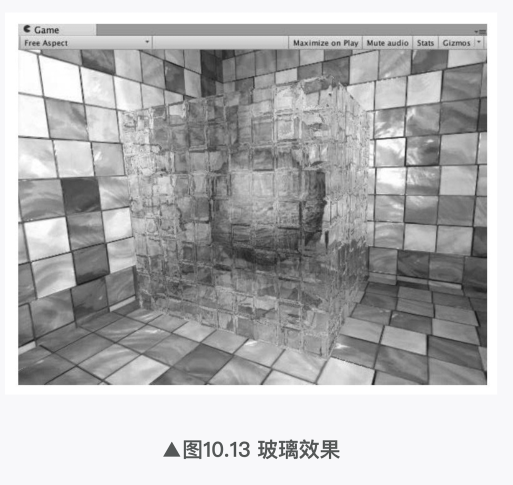
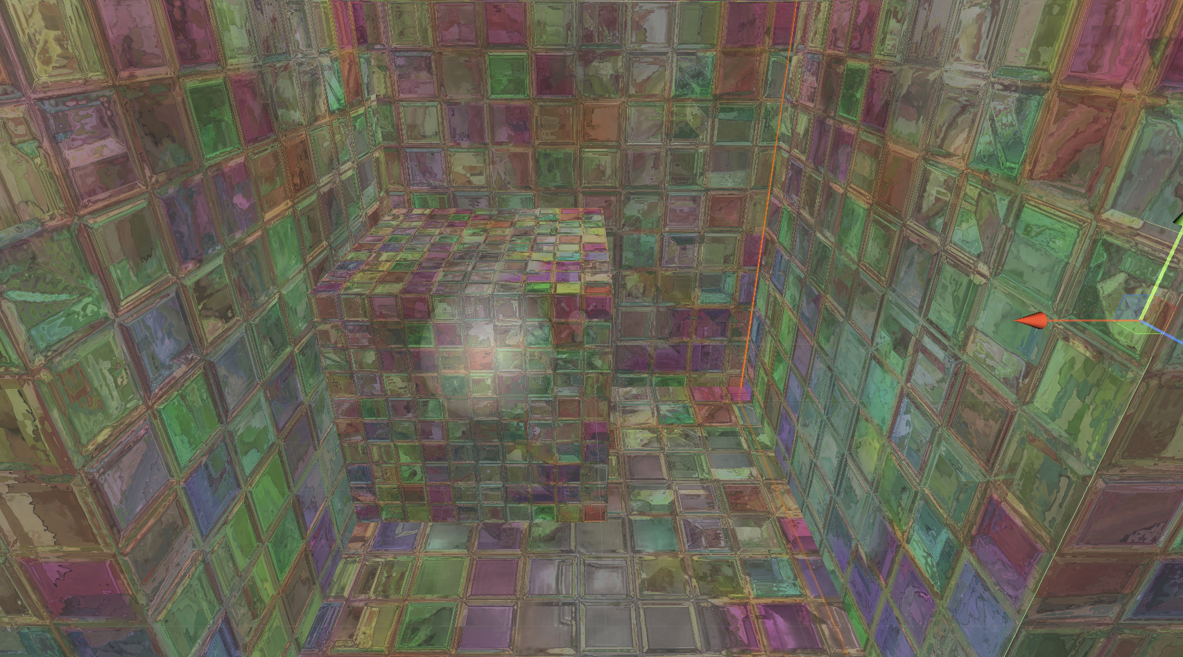
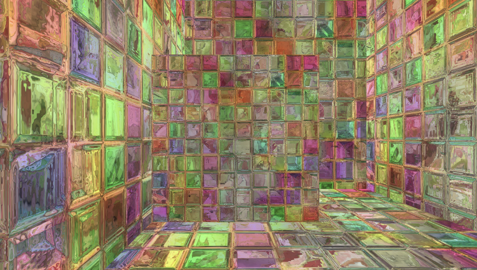
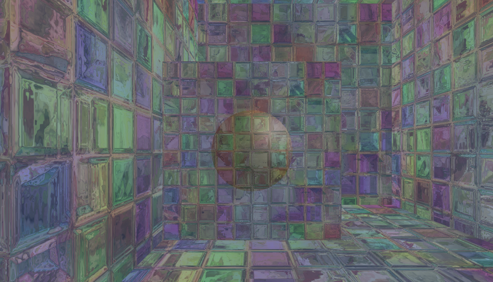
本节中,我们将会使用GrabPass来模拟一个玻璃效果。在学习完本节后,我们可以得到类似图10.13中的效果。这种效果的实现非常简单,我们首先使用一张法线纹理来修改模型的法线信息,然后使用了10.1节介绍的反射方法,通过一个Cubemap来模拟玻璃的反射,而在模拟折射时,则使用了GrabPass获取玻璃后面的屏幕图像,并使用切线空间下的法线对屏幕纹理坐标偏移后,再对屏幕图像进行采样来模拟近似的折射效果。
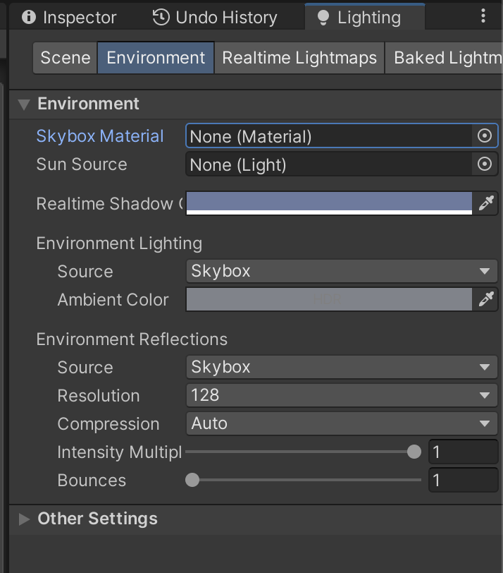
(1)新建一个场景。在本书资源中,该场景名为Scene_10_2_2。在Unity 5.2中,默认情况下场景将包含一个摄像机和一个平行光,并且使用了内置的天空盒子。在Window → Lighting→Skybox中去掉场景中的天空盒子。
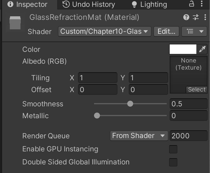
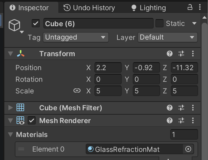
(2)新建一个材质。在本书资源中,该材质名为GlassRefractionMat。
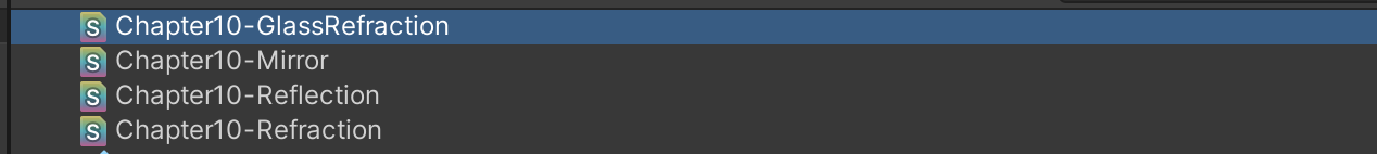
(3)新建一个Unity Shader。在本书资源中,该Shader名为Chapter10-GlassRefraction。把新的Unity Shader赋给第2步中创建的材质。
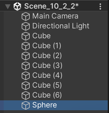
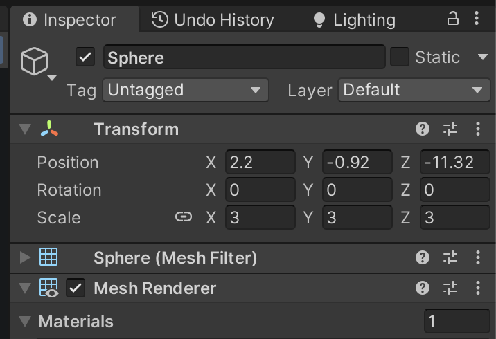
(4)构建一个测试玻璃效果的场景。在本书资源的实现中,我们构建了一个由6面墙围成的封闭房间,并在房间中放置了一个立方体和一个球体,其中球体位于立方体内部,这是为了模拟玻璃对内部物体的折射效果。把第2步中创建的材质赋给立方体。
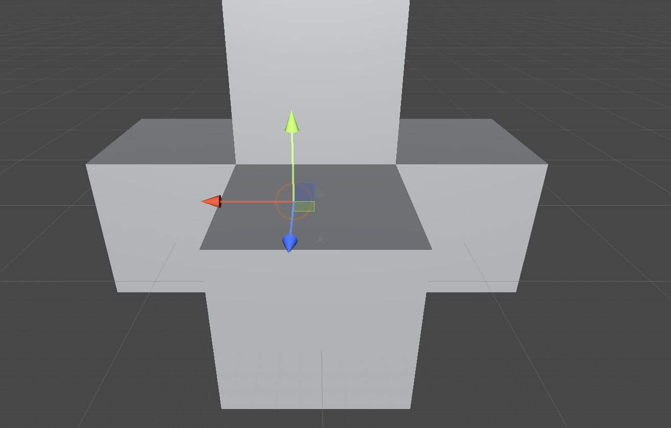
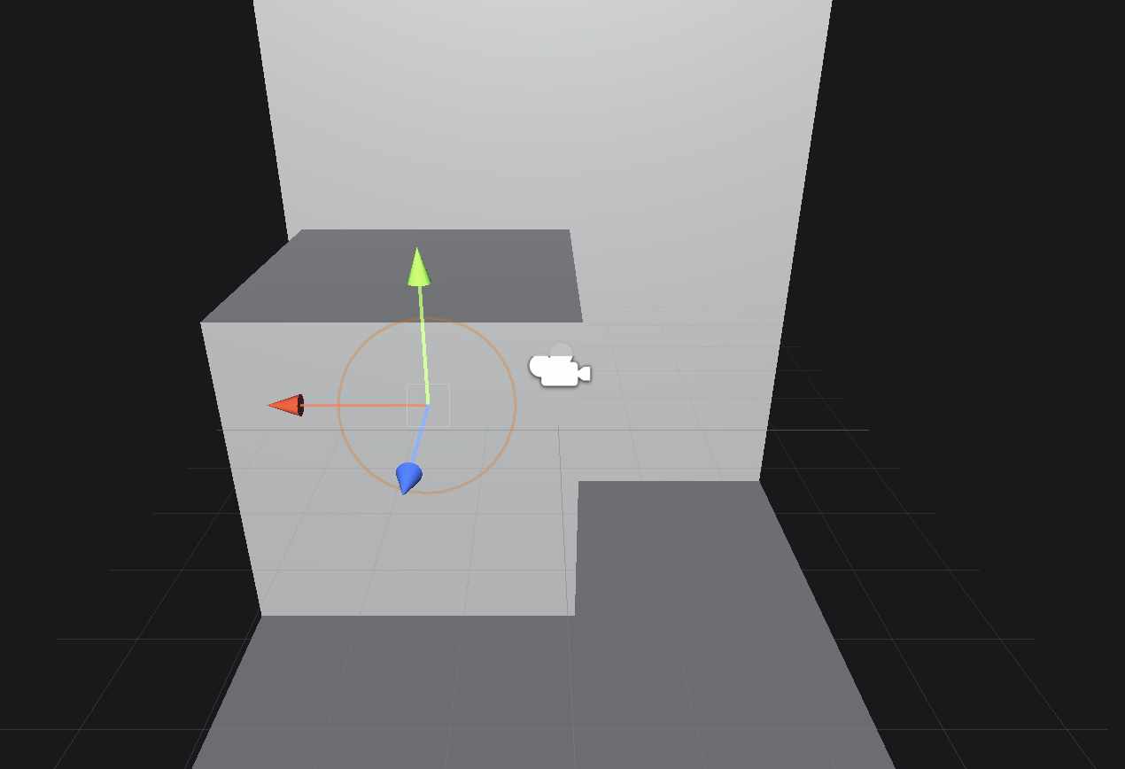
把正方体放墙角,球放正方体中间
墙角算下小正方体中心和大正方体中心之间的距离,用大正方体的中心坐标算得小正方体的坐标。(也不一定要这样)
(5)为了得到本场景适用的环境映射纹理,我们使用了10.1.2节中实现的创建立方体纹理的脚本(通过Gameobject → Render into Cubemap打开编辑窗口)来创建它,如图10.14所示。在本书资源中,该Cubemap名为Glass_Cubemap。
下载下来就行
完成准备工作后,打开Chapter10-GlassRefraction,对它进行如下关键修改。
(1)首先,我们需要声明该Shader使用的各个属性:
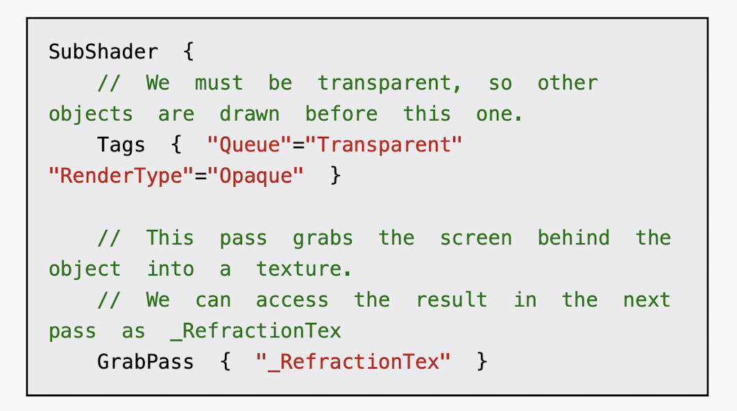
(2)定义相应的渲染队列,并使用GrabPass来获取屏幕图像:
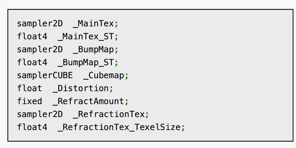
(3)定义渲染玻璃所需的Pass。为了在Shader中访问各个属性,我们首先需要定义它们对应的变量:
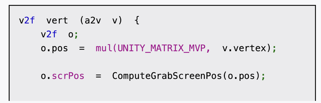
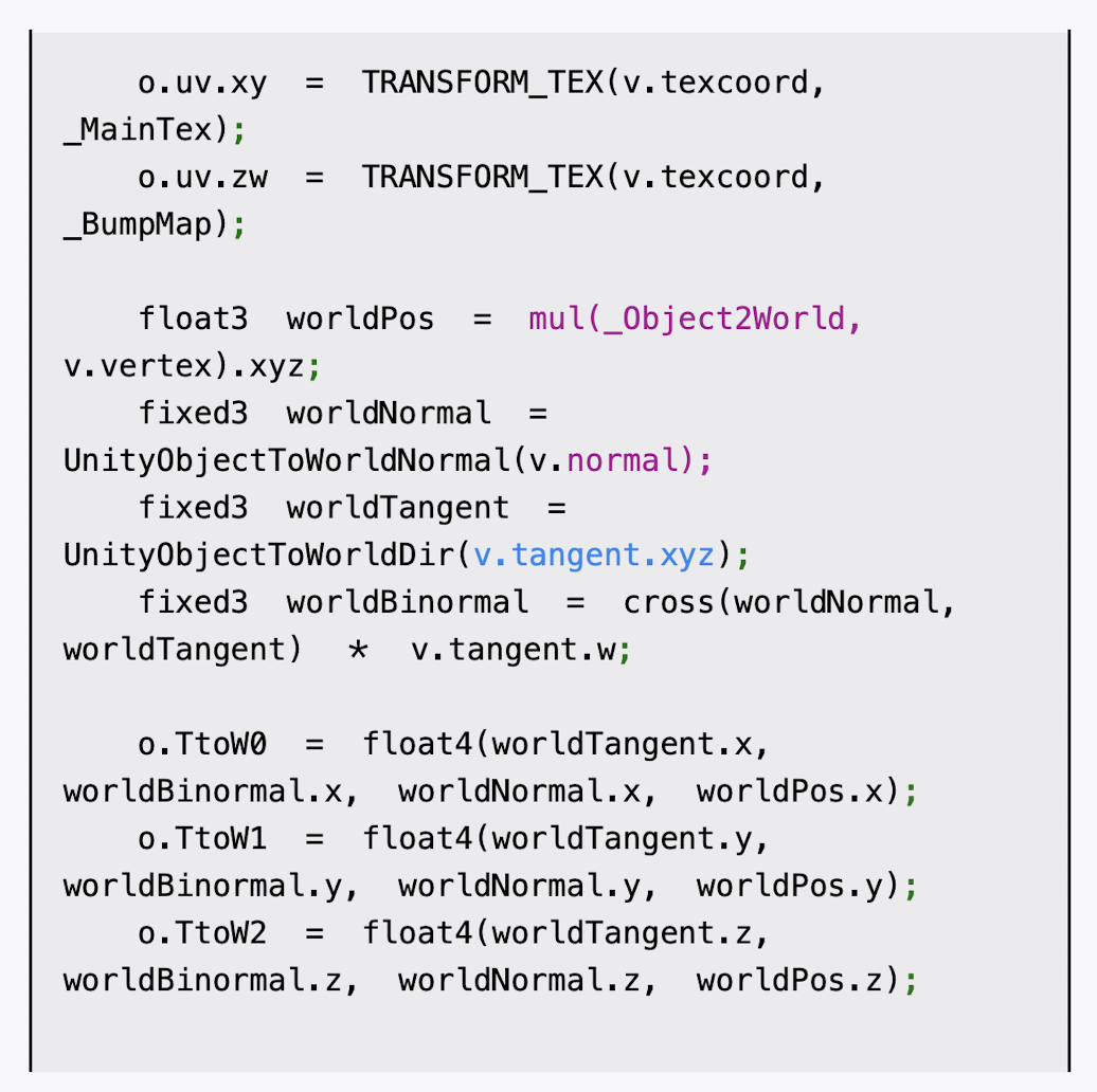
(4)我们首先需要定义顶点着色器:
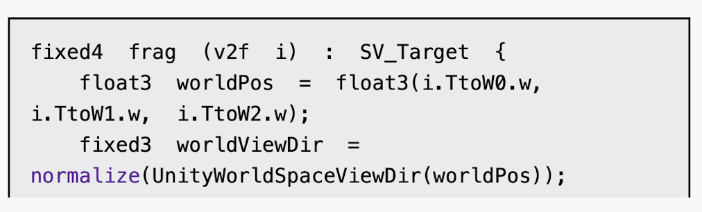
(5)然后,定义片元着色器:


cs
// Upgrade NOTE: replaced '_Object2World' with 'unity_ObjectToWorld'
// Upgrade NOTE: replaced 'mul(UNITY_MATRIX_MVP,*)' with 'UnityObjectToClipPos(*)'
Shader "Custom/Chapter10-GlassRefraction"
{
Properties {
_MainTex ("Main Tex", 2D) = "white" {} //_MainTex是该玻璃的材质纹理,默认为白色纹理
_BumpMap ("Normal Map", 2D) = "bump" {} //_BumpMap是玻璃的法线纹理
_Cubemap ("Environment Cubemap", Cube) = "_Skybox" {} //_Cubemap是用于模拟反射的环境纹理
_Distortion ("Distortion", Range(0, 100)) = 10 //_Distortion则用于控制模拟折射时图像的扭曲程度
_RefractAmount ("Refract Amount", Range(0.0, 1.0)) = 1.0 //_RefractAmount用于控制折射程度,当_RefractAmount值为0时,该玻璃只包含反射效果,当_RefractAmount值为1时,该玻璃只包括折射效果。
}
SubShader {
// We must be transparent, so other objects are drawn before this one.
Tags { "Queue"="Transparent" "RenderType"="Opaque" }
// This pass grabs the screen behind the object into a texture.
// We can access the result in the next pass as _RefractionTex
GrabPass { "_RefractionTex" }
Pass {
CGPROGRAM
#pragma vertex vert
#pragma fragment frag
#include "UnityCG.cginc"
sampler2D _MainTex;
float4 _MainTex_ST;
sampler2D _BumpMap;
float4 _BumpMap_ST;
samplerCUBE _Cubemap;
float _Distortion;
fixed _RefractAmount;
sampler2D _RefractionTex;
float4 _RefractionTex_TexelSize;
struct a2v {
float4 vertex : POSITION;
float3 normal : NORMAL;
float4 tangent : TANGENT;
float2 texcoord: TEXCOORD0;
};
struct v2f {
float4 pos : SV_POSITION;
float4 scrPos : TEXCOORD0;
float4 uv : TEXCOORD1;
float4 TtoW0 : TEXCOORD2;
float4 TtoW1 : TEXCOORD3;
float4 TtoW2 : TEXCOORD4;
};
v2f vert (a2v v) {
v2f o;
o.pos = UnityObjectToClipPos(v.vertex);
o.scrPos = ComputeGrabScreenPos(o.pos); //ComputeGrabScreenPos函数来得到对应被抓取的屏幕图像的采样坐标
o.uv.xy = TRANSFORM_TEX(v.texcoord, _MainTex);
o.uv.zw = TRANSFORM_TEX(v.texcoord, _BumpMap);
float3 worldPos = mul(unity_ObjectToWorld, v.vertex).xyz;
fixed3 worldNormal = UnityObjectToWorldNormal(v.normal);
fixed3 worldTangent = UnityObjectToWorldDir(v.tangent.xyz);
fixed3 worldBinormal = cross(worldNormal, worldTangent) * v.tangent.w;
o.TtoW0 = float4(worldTangent.x, worldBinormal.x, worldNormal.x, worldPos.x);
o.TtoW1 = float4(worldTangent.y, worldBinormal.y, worldNormal.y, worldPos.y);
o.TtoW2 = float4(worldTangent.z, worldBinormal.z, worldNormal.z, worldPos.z);
return o;
}
fixed4 frag (v2f i) : SV_Target {
float3 worldPos = float3(i.TtoW0.w, i.TtoW1.w, i.TtoW2.w);
fixed3 worldViewDir = normalize(UnityWorldSpaceViewDir(worldPos));
// Get the normal in tangent space
fixed3 bump = UnpackNormal(tex2D(_BumpMap, i.uv.zw));
// Compute the offset in tangent space
float2 offset = bump.xy * _Distortion * _RefractionTex_TexelSize.xy; // 计算折射偏移量:用法线贴图扰动折射坐标,偏移量 = 法线方向 × 扭曲强度 × 纹理像素尺寸
i.scrPos.xy = offset * i.scrPos.z + i.scrPos.xy;
fixed3 refrCol = tex2D(_RefractionTex, i.scrPos.xy/i.scrPos.w).rgb; // 采样屏幕空间折射纹理:将屏幕坐标归一化后采样折射纹理,i.scrPos.xy / i.scrPos.w- 透视除法,将坐标归一化到[0,1]范围
// Convert the normal to world space
bump = normalize(half3(dot(i.TtoW0.xyz, bump), dot(i.TtoW1.xyz, bump), dot(i.TtoW2.xyz, bump))); // 将法线从切线空间转换到世界空间:使用TBN矩阵进行坐标变换
fixed3 reflDir = reflect(-worldViewDir, bump);
fixed4 texColor = tex2D(_MainTex, i.uv.xy);
fixed3 reflCol = texCUBE(_Cubemap, reflDir).rgb * texColor.rgb;
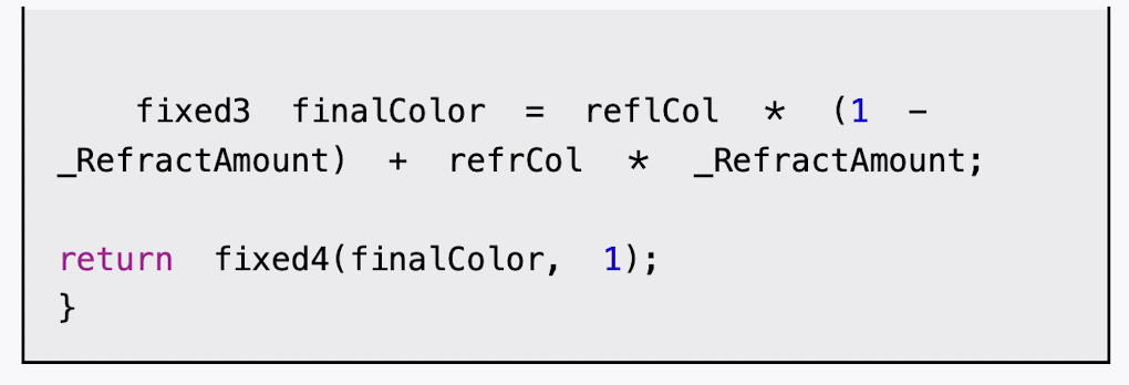
fixed3 finalColor = reflCol * (1 - _RefractAmount) + refrCol * _RefractAmount;
return fixed4(finalColor, 1);
}
ENDCG
}
}
FallBack "Diffuse"
}完成后,我们把本书资源中的Glass_Diffuse.jpg和Glass_Normal.jpg文件赋给材质的Main Tex和Normal Map属性,把之前创建的Glass_Cubemap赋给Environment Cubemap属性,再调整_RefractAmount属性即可得到类似图10.13中的玻璃效果。


0
0.5
1