Renesas RH850-U2A Inter-Processor Interrupt Function
- [1 Initial Setting](#1 Initial Setting)
- [2 Inter-PE Interrupt Request](#2 Inter-PE Interrupt Request)
- [3 Request Mask Function](#3 Request Mask Function)
- [4 Inter-PE Interrupt Requests of Multiple Systems](#4 Inter-PE Interrupt Requests of Multiple Systems)
- [5 Inter-PE Interrupt Request Clear Function](#5 Inter-PE Interrupt Request Clear Function)
1 Initial Setting
Initial setting of authorized PEs by the IPInENm register must be made before IPIR is used. An example of initial setting is given below.
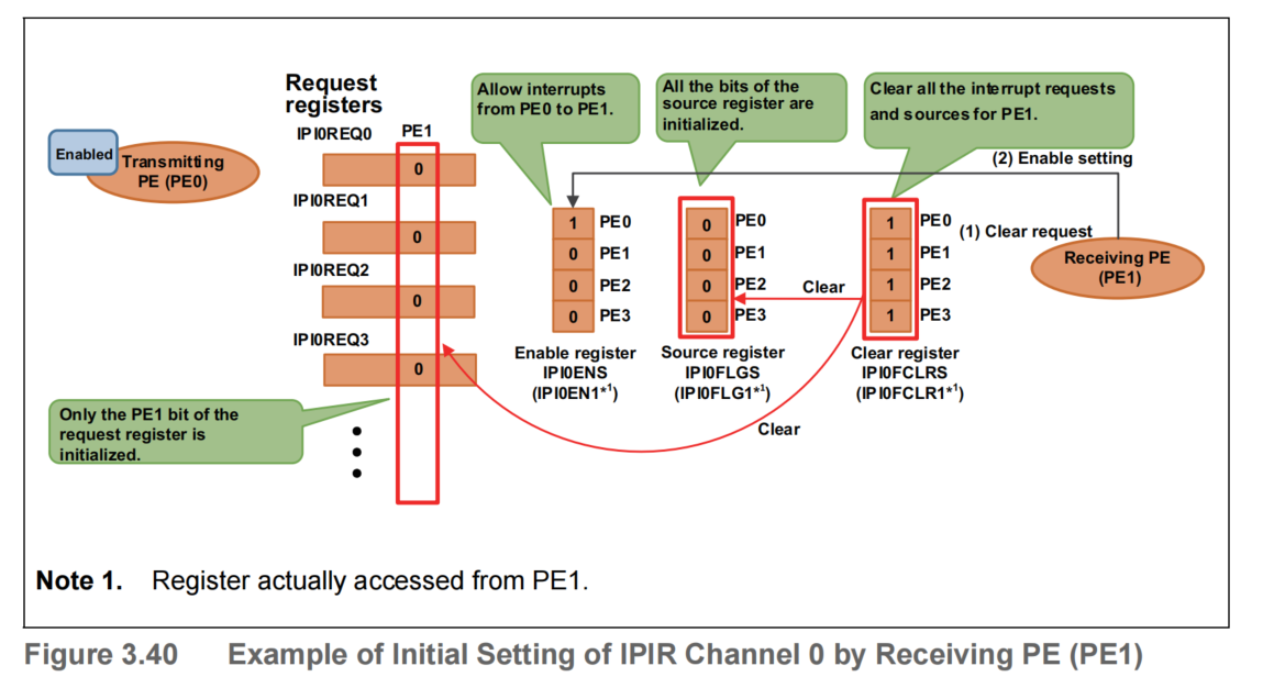
(1) Initial Setting by Receiving PE
Figure 3.40 shows an example of the initial setting of IPIR channel 0 by PE1, which is a receiving PE.
First, if IPIR has already been used and the values of bits IPI0REQ0 to 31 and the value of the IPI0FLG1 register have changed from the initial values, PE1 writes 0FH to the IPI0FCLRS (= IPI0FCLR1) register to clear bits IPI0REQ0 to 31 and the IPI0FLG1 register. If the values of bits IPI0REQ0 to 31 and the IPI0FLG1 register are the initial values, for example after hardware reset, this clearing operation is not required.
Next, PE1 writes 01H to the IPI0ENS (= IPI0EN1) register to accept interrupt requests from PE0 to PE1. Like for the clear register, upon completion of setting of the enable register, PE1 can accept interrupt requests from PE0.
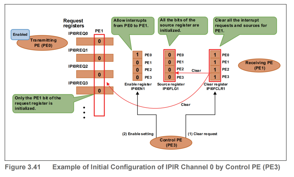
(2) Initial Setting by Control PE
An example of initial setting from a PE other than a receiving PE is shown below. In this section, the PE that performs the initial setting is called the control PE for the sake of convenience. Figure 3.41shows an example of the initial setting of IPIR channel 0 by PE3, which is the control PE. In this figure, bits PE0 to 3 of each register are omitted.
First, if IPIR has already been used and the values of bits IPI0REQ0 to 31 and the value of the IPI0FLG1 register have changed from the initial values, PE3 writes 0FH to the IPI0FCLR1 register to clear bits IPI0REQ0 to 31 and the IPI0FLG1 register. If the values of bits IPI0REQ0 to 31 and the IPI0FLG1 register are the initial values, for example after hardware reset, this clearing operation is not required.
Next, PE3 writes 01H to the IPI0EN1 register to accept interrupt requests from PE0 to PE1. Like for the clear register, upon completion of setting of the enable register, PE1 can accept interrupt requests from PE0.
2 Inter-PE Interrupt Request
Figure 3.42 shows an example of the operation when PE0 sends an inter-PE interrupt request to PE1 using IPIR channel 0. In this figure, bits PE0 to 3 of each register are omitted. In this example, the initial setting is set to IPI0EN1 in advance to enable inter-PE interrupt requests from PE0. For an operation example of the initial setting, see Section 3.4.3.1, Initial Setting. The following describes an example of accessing the registers through the self-register.
First, PE0, which is the transmitting PE, reads the IPI0REQS (= IPI0REQ0) register and checks that the value of the IPI0REQS1 (= IPI0REQ01) bit is 0B. If the value of the IPI0REQS1 (= IPI0REQ01) bit is 1B, this means that the previous inter-PE interrupt request from PE0 to PE1 has not been accepted by PE1, and thus a new inter-PE interrupt request cannot be issued. If it is confirmed that the value of the IPI0REQS1 (= IPI0REQ01) bit is 0B and thus an inter-PE interrupt request from PE0 to PE1 is enabled, PE0 sets the IPI0REQS1 (= IPI0REQ01) bit to 1B to issue an inter-PE interrupt request from PE1. Because inter-PE interrupts from PE0 to PE1 are enabled by the IPI0EN1 register, when PE0 sets the IPI0REQS1 (= IPI0REQ01) bit to 1B, the IPI0FLG11 bit is automatically set to 1B, and an inter-PE interrupt request signal is output to PE1 from IPIR.
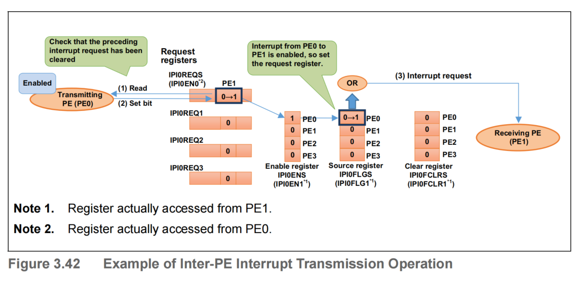
Figure 3.43 shows an example of the operation when PE1 receives an inter-PE interrupt request from PE0 using IPIR channel 0. When PE1, which is the receiving PE, receives an inter-PE interrupt request signal, it reads the IPI0FLGS (= IPI0FLG1) register, and because the value of the IPI0FLGS0 (= IPI0FLG10) bit is 1B, it recognizes that the inter-PE interrupt request has been sent from PE0. But if the request side clears the request, the value of it is 0B. After verifying the source of the inter-PE interrupt, PE1 sets the IPI0FCLRS[0] (= IPI0FCLR1[0]) bit to 1B, and the processing transitions to the inter-PE interrupt processing. The IPI0REQS[1] (= IPI0REQ0[1]) bit and the IPI0FLGS (= IPI0FLG1) bit are automatically cleared when the IPI0FCLRS0 (= IPI0FCLR10) bit is set to 1B by PE1.
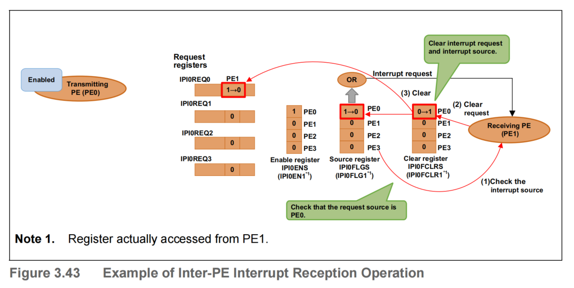
Figure 3.44 shows the operation flow from initial setting of IPIR by the receiving PE (PE1), to sending of an inter-PE interrupt request by the transmitting PE (PE0), and completion of reception of that inter-PE interrupt request by the receiving PE (PE1).
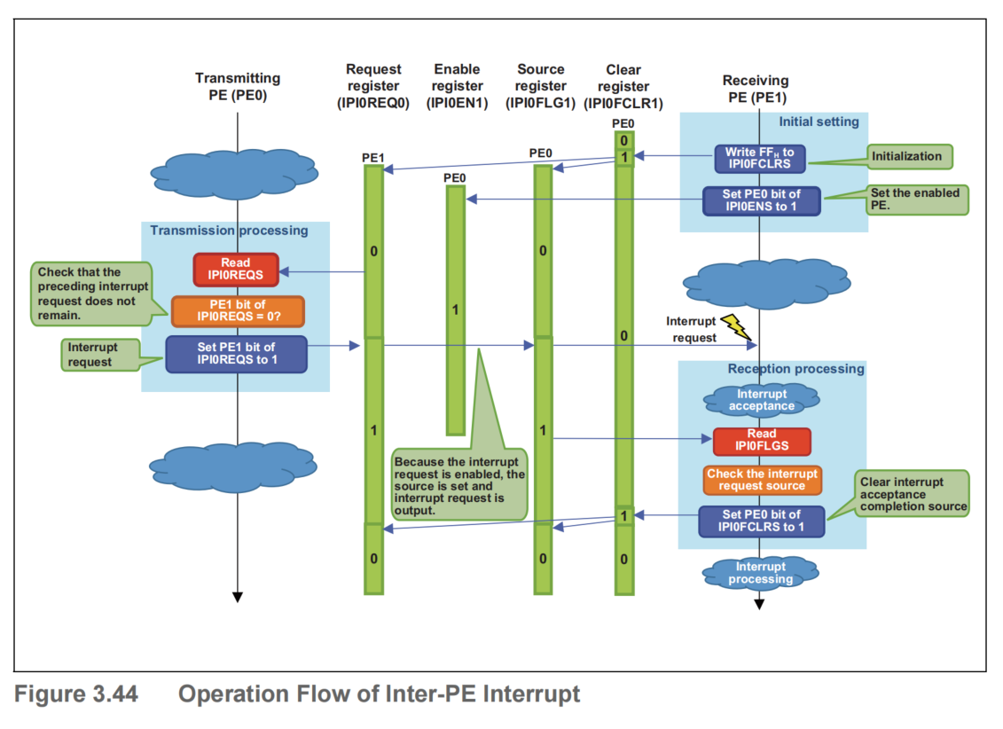
Note that if a new inter-PE interrupt request is generated to the same receiving PE before the source register is cleared by the receiving PE with the clear register, the bit corresponding to the new transmitting PE in the source register will be set to 1B, but the inter-PE interrupt request signal being retained high, the second and subsequent inter-PE interrupt requests will not be output. Therefore, the processing when multiple sources occur when the receiving PE has received an inter-PE interrupt request must be controlled by software.
The transmitting PE can detect whether the preceding inter-PE interrupt request was successfully received by the receiving PE, by checking the value of the request register. To monitor the request register with a polling loop, it is recommended to curb the bus load by executing the snooze instruction within the polling loop in order to avoid the bus system occupation for extended periods of time.
(1) Sample Code
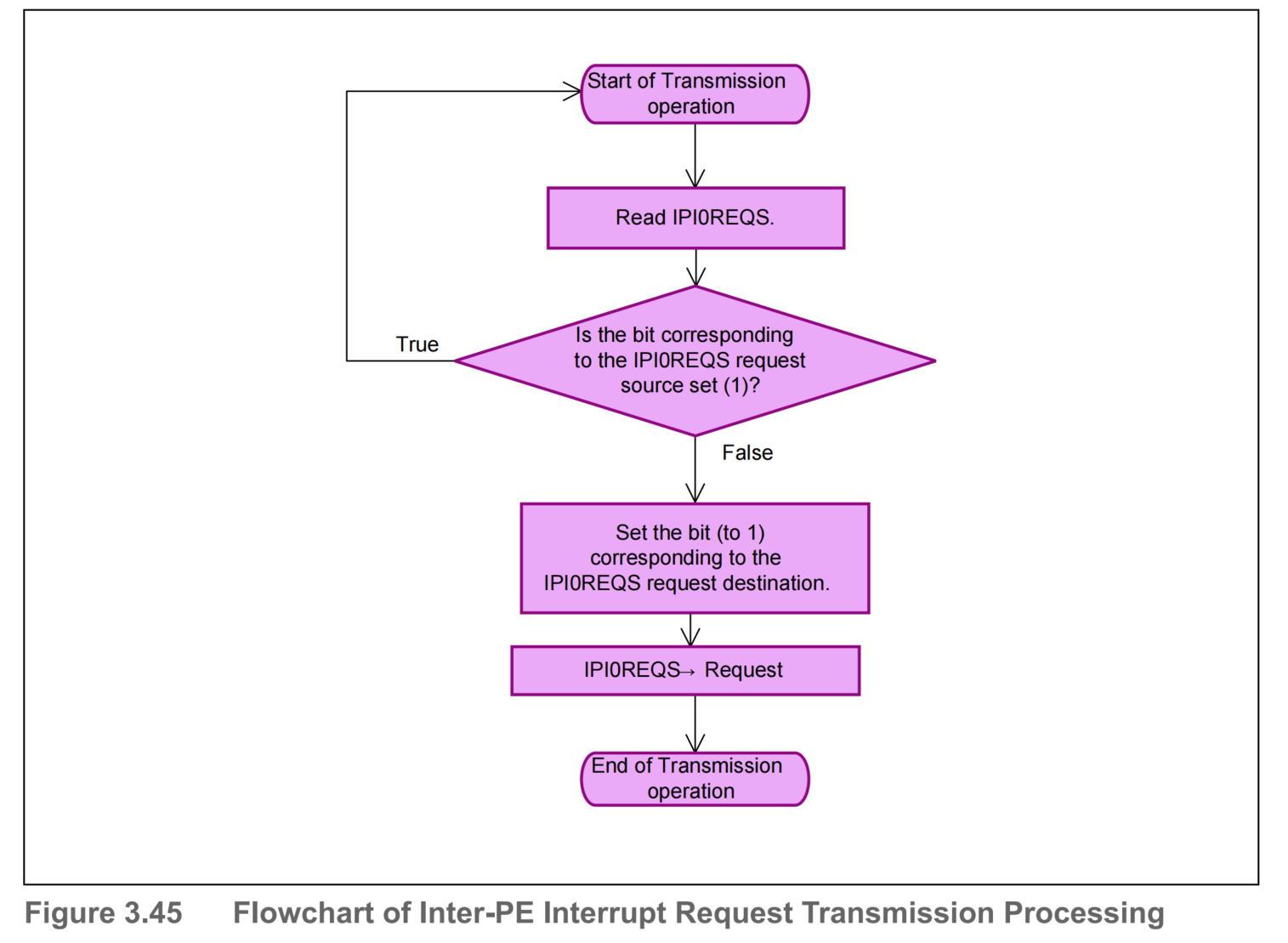
(a) Transmission Processing
Figure 3.45 shows a sample flowchart of the inter-PE interrupt request transmission processing using IPIR channel 0.
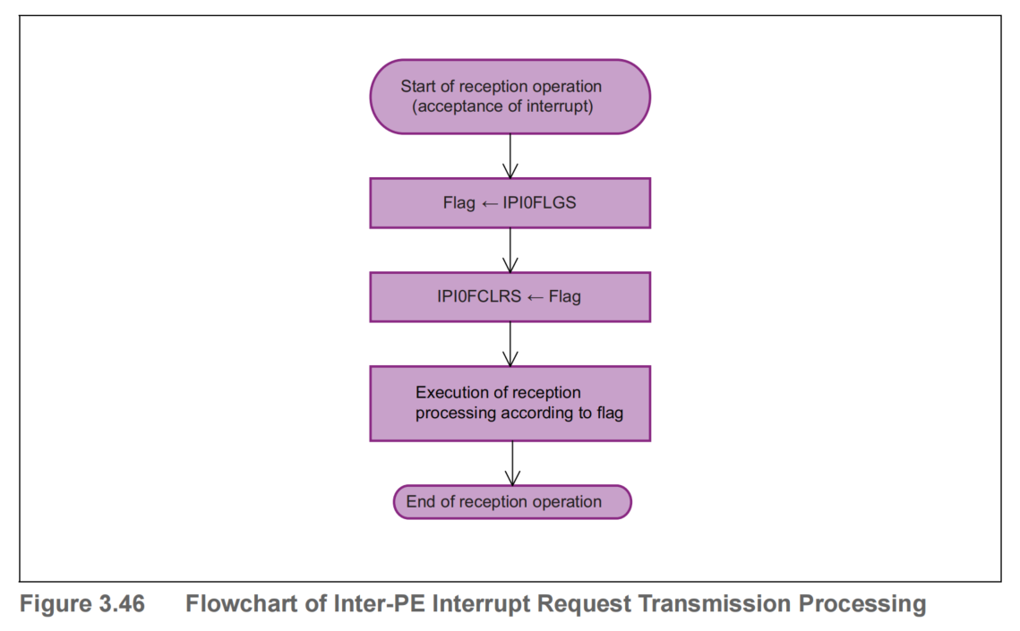
(b) Reception Processing
Figure 3.46 shows a sample flowchart of the inter-PE interrupt request reception processing using IPIR channel 0. To prevent source flag loss, the source flag & source clear register configuration is used.
3 Request Mask Function
Inter-PE interrupt requests disabled by the IPInENm register setting are ignored. Figure 3.47 shows an example of the operation when an inter-PE interrupt is requested from a disabled PE. In this figure, bits PE0 to 3 of each register are omitted. In this example, the initial setting is set to IPI0EN1 in advance to prohibit inter-PE interrupt requests from PE2 to PE1. For an operation example of the initial setting, see Section 1, Initial Setting.
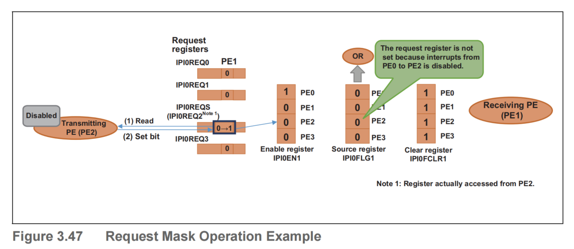
Even if PE2 sets IPI0REQS1 (= IPI0REQ21) to 1B to request PE1 to issue an inter-PE interrupt, inter-PE interrupts from PE2 to PE1 are prohibited, so the IPInFLG12 bit remains 0B and no interrupt request signal is output.
If the transmitting PE disabled by the IPInENm register setting unintentionally writes 1B to the IPI0REQm register, the IPI0REQm register can be cleared by using the IPInRCLRm register. For details, see Section 5, Inter-PE Interrupt Request Clear Function.
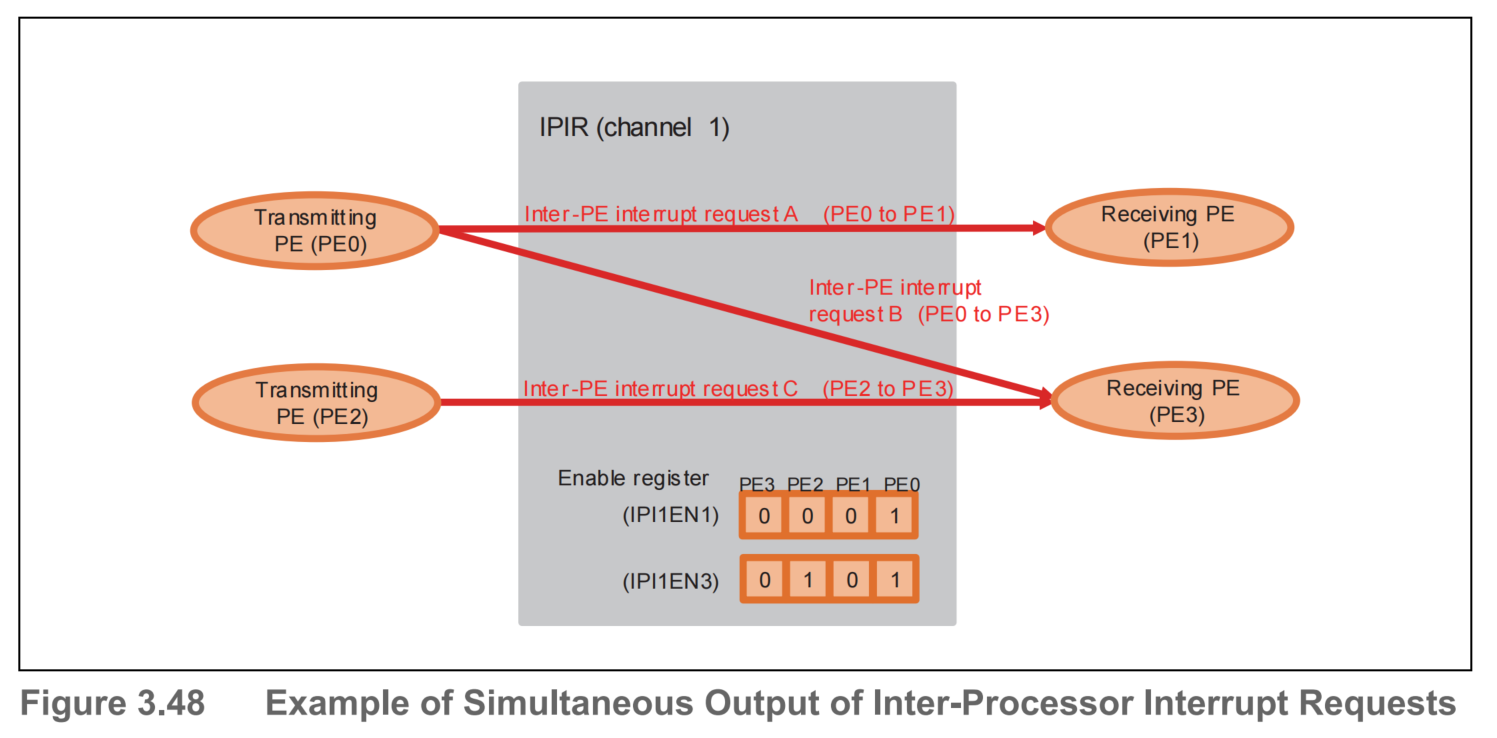
4 Inter-PE Interrupt Requests of Multiple Systems
If the combination of the transmitting PE and receiving PE differs, multiple inter-PE interrupt requests can be output simultaneously on one channel of IPIR. For example it is possible to output inter-PE interrupt request A (PE0 to PE1) and inter-PE interrupt request B (PE1 to PE0) on channel 1 of IPIR simultaneously. Each register operates independently when the combination of the transmitting PE and receiving PE differs, so multiple inter-PE interrupt requests can be output simultaneously.
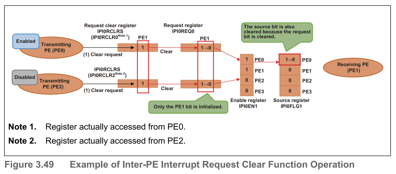
5 Inter-PE Interrupt Request Clear Function
The IPInREQmx bit can be cleared by setting the IPInRCLRmx bit to 1B, allowing you to cancel inter-PE interrupt requests from the transmitting PE. If inter-PE interrupt requests from the transmitting PE are enabled by the IPInENxm bit, the IPInFLGxm bit is also cleared at the same time as the IPInREQmx bit is cleared. However, the receiving PE may in some cases accept the inter-PE interrupt while the cancellation processing takes place.
Figure 3.49 shows an example of the operation to clear inter-PE interrupt requests from PE0 and PE2 to PE1. When PE0 writes 1B to the IPI0RCLRS1 (= IPI0RCLR01) bit, the IPI0REQ01 bit is cleared. Moreover, because inter-PE interrupt requests from PE0 to PE1 are enabled by the IPI0EN1 register setting, IPI0FLG10 is also cleared.
When PE2 writes 1B to the IPI0RCLRS1 (= IPI0RCLR21) bit, the IPI0REQ21 bit is cleared. Here, inter-PE interrupt requests from PE2 to PE1 are disabled by the IPI0EN1 register setting, so the IPI0RCLR2 register does not affect the value of the IPI0FLG1 register.