STM32 I2C访问配置霍尔磁角度传感器MT6701
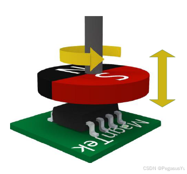
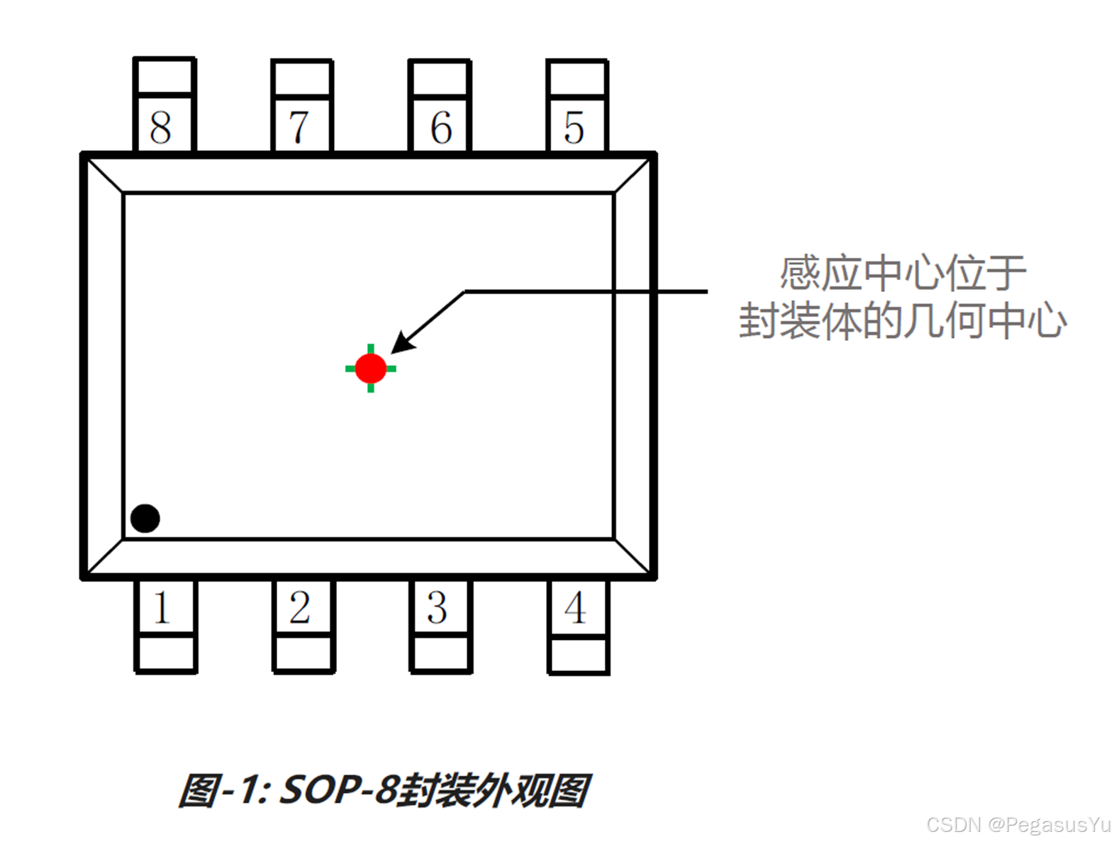
电机运转时,可以通过编码器/霍尔磁角度传感器如MT6701获取角度和位置以及计算出转速等信息。MT6701芯片应用需采用径向充磁的圆磁铁固定于电机轴侧面,将芯片感应中心对准磁铁进行测量。
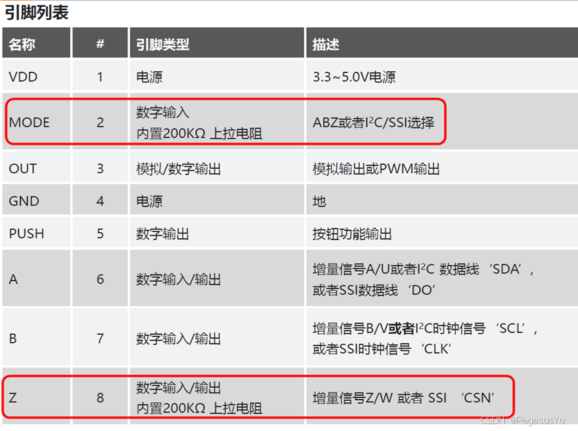
MT6701具有多种输出模式,需要先通过I2C总线进行模式配置,然后再进行输出数据的解析。而MT6701的管脚具有复用特性,需要先进行模式的配置,才能使用I2C访问方式。
模式控制简单总结如下:
- 采用I2C访问方式, MODE管脚拉到高电平,Z管脚为输入管脚,拉到高电平
- 采用SSI访问方式,MODE管脚拉到高电平,Z管脚为输入管脚,拉到低电平(SSI片选有效),然后控制端发送SSI时钟信号(B管脚)并获得SSI数据(A管脚)
- 采用ABZ/ABN访问方式,MODE管脚拉到低电平,此时Z管脚为输出管脚
这里介绍采用TM32CUBEIDE开发环境,及STM32F401RCT6访问配置MT6701的过程。
STM32硬件接口配置
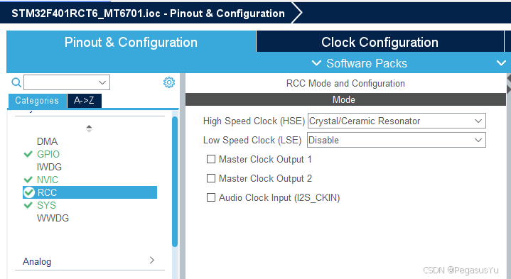
首先进行STM32CUBEIDE的工程配置,建立新的工程并配置时钟和接口:
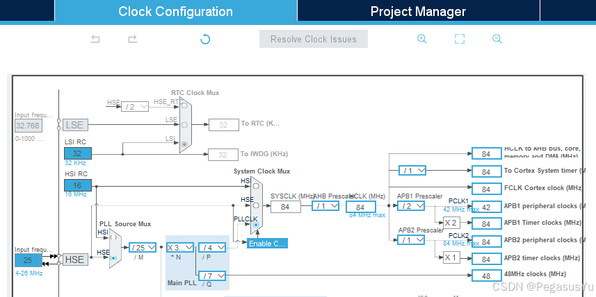
48MHz时钟是配置给USB VCOM所用,先要进行USB VCOM配置:
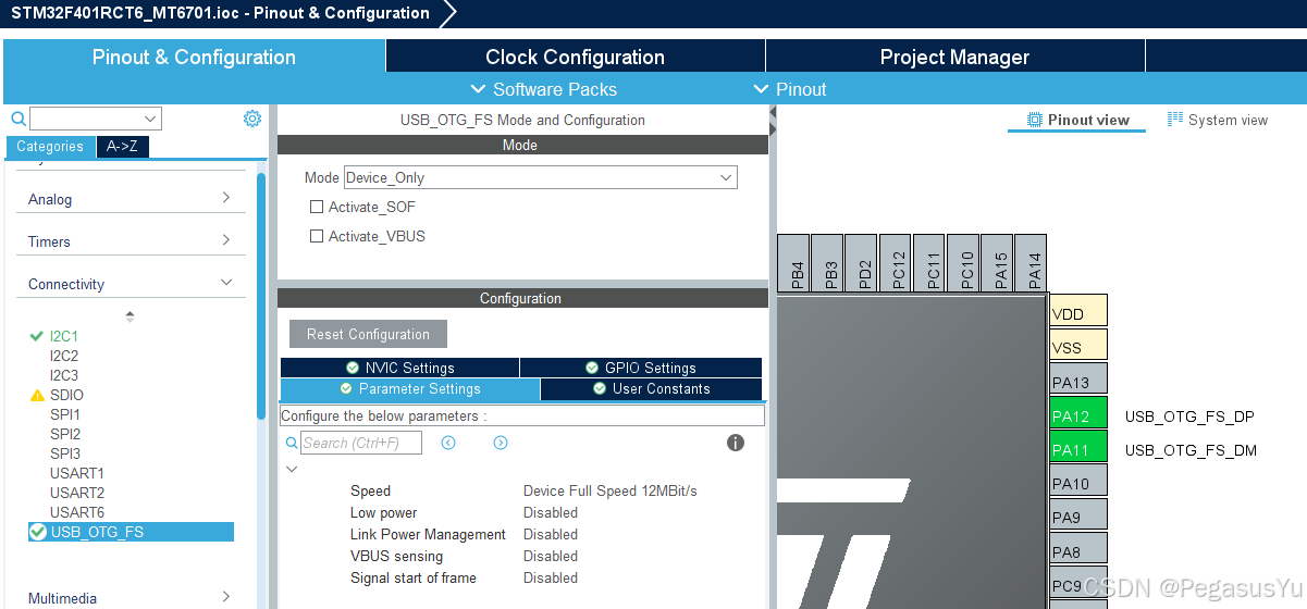
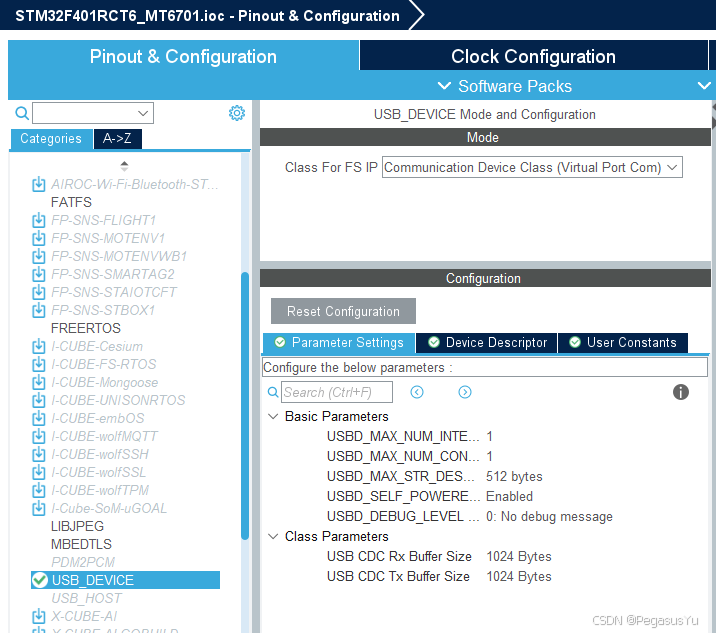
USB VCOM的配置使用也可以参考《STM32 USB VCOM和HID的区别,配置及Echo功能实现(HAL)》
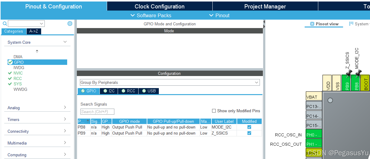
然后选择两个GPIO连接到MODE管脚和Z管脚,并初始化为高电平输出:
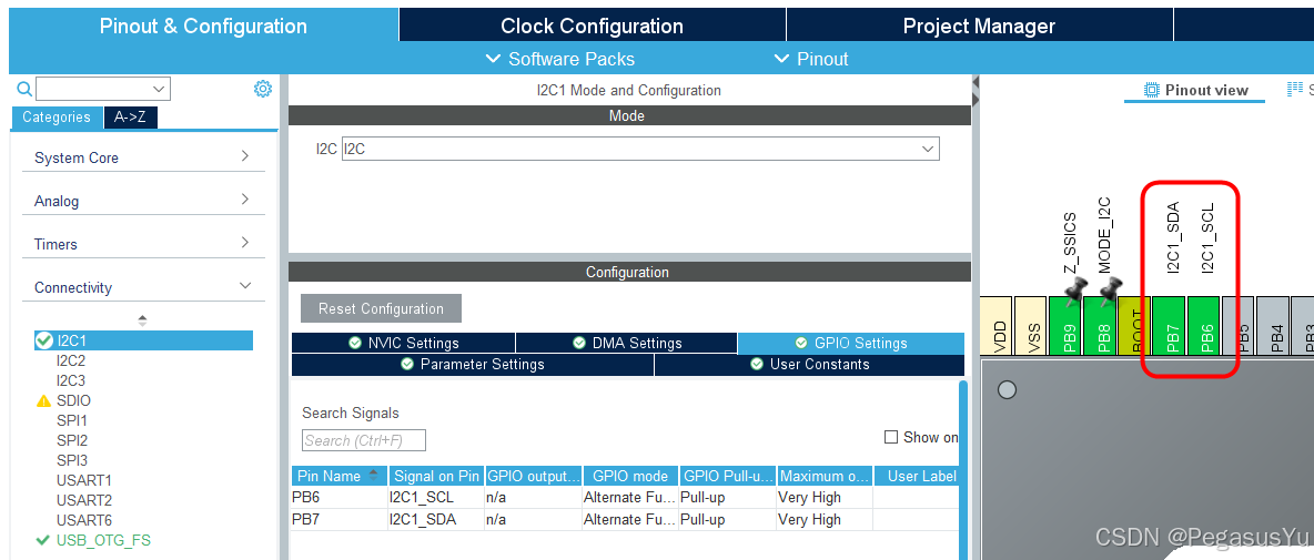
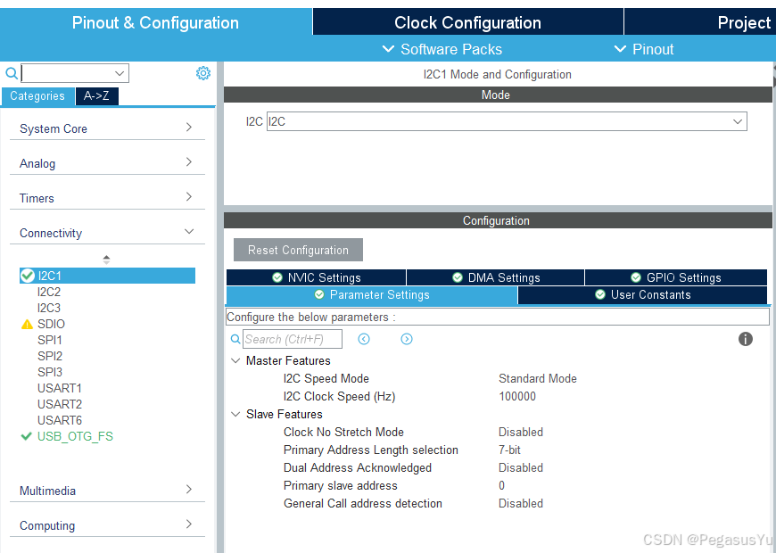
配置硬件I2C:
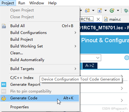
保存并产生基本工程代码:
MT6701 I2C访问寄存器
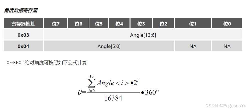
MT6701的I2C访问7 bit地址为二进制0000110。 0x03和0x04寄存器里存放可读取角度信息:
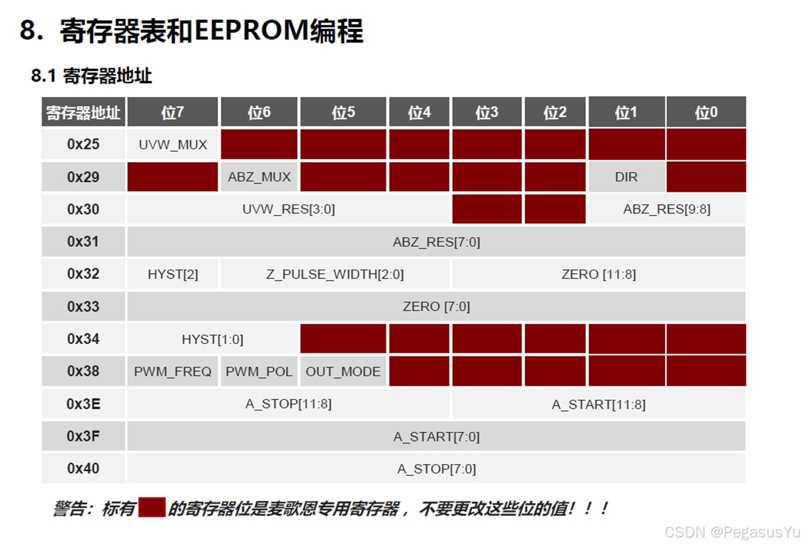
MT6701的控制寄存器组定义:
MT6701有一个OUT管脚,可以配置为模拟输出或PWM输出。本例将OUT管脚配置为PWM角度输出据输出。而主功能模式输出为ABZ模式。
PWM角度数据的STM32检测解析参考:《STM32解析霍尔磁角度传感器PWM脉冲角度数据》
AB数据的STM32检测解析参考:《STM32解析霍尔磁角度传感器AB脉冲数据》
对于一些电机驱动芯片(如TMC系列步进电机驱动芯片)支持ABZ/ABN解析, 则将三个信号直接连接到电机驱动芯片。
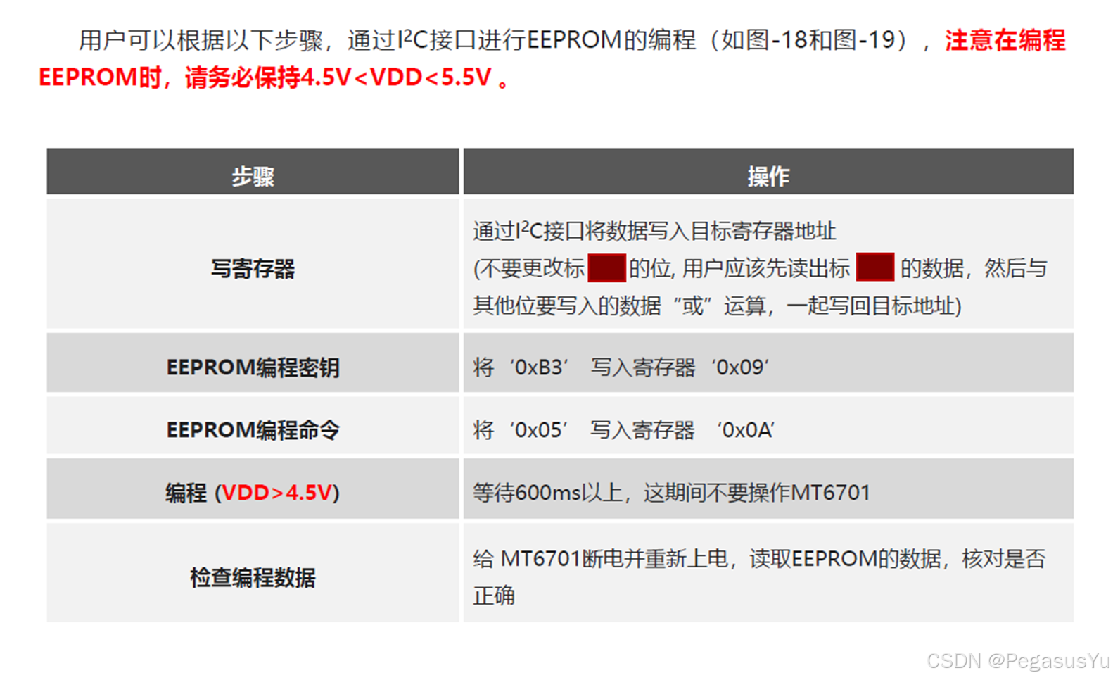
MT6701自带EEPROM保存功能,通过如下的指令可以将当前配置保存到非易失存储,并在重新上电后被读取应用:
STM32功能规划
本例程将实现如下功能:
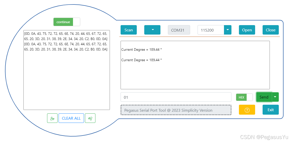
- 通过USB VCOM可以发送十六进制单字节命令到STM32
- 发送0x01时通过I2C读取当前电机轴的角度位置信息
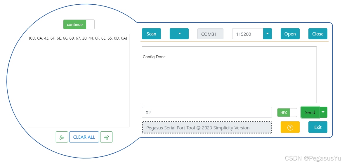
- 发送0x02时通过I2C配置MT6701在ABZ模式的工作参数(非差分ABZ输出,角度增加方向,一圈发出200个脉冲,OUT较为PWM输出模式,PWM输出频率选择等等)
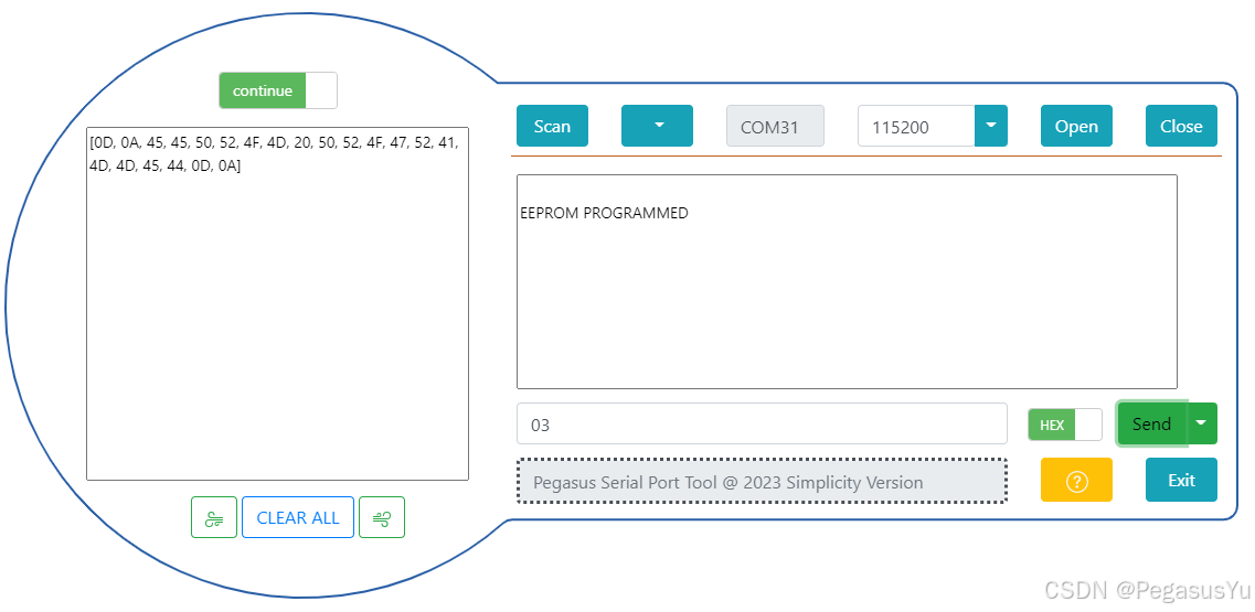
- 发送0x03时将MT6701的配置烧录进EEPROM
重启系统后(MODE管脚拉到低电平),MT6701将输出ABZ数据和PWM角度数据。
STM32工程代码
首先设置USB VCOM接收串口指令:
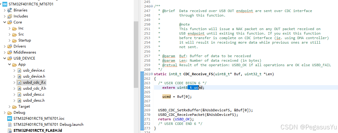
c
static int8_t CDC_Receive_FS(uint8_t* Buf, uint32_t *Len)
{
  /* USER CODE BEGIN 6 */
	extern uint8_t ucmd;

	ucmd = Buf[0];


  USBD_CDC_SetRxBuffer(&hUsbDeviceFS, &Buf[0]);
  USBD_CDC_ReceivePacket(&hUsbDeviceFS);
  return (USBD_OK);
  /* USER CODE END 6 */
}
在main.c文件里实现全部的控制逻辑:
c
/* USER CODE BEGIN Header */
/**
  ******************************************************************************
  * @file           : main.c
  * @brief          : Main program body
  ******************************************************************************
  * @attention
  *
  * Copyright (c) 2026 STMicroelectronics.
  * All rights reserved.
  *
  * This software is licensed under terms that can be found in the LICENSE file
  * in the root directory of this software component.
  * If no LICENSE file comes with this software, it is provided AS-IS.
  *
  ******************************************************************************
  */
//For i2c access
//Pin "mode" = high
//Pin "SSI CS = high
/* USER CODE END Header */
/* Includes ------------------------------------------------------------------*/
#include "main.h"
#include "usb_device.h"

/* Private includes ----------------------------------------------------------*/
/* USER CODE BEGIN Includes */
#include "string.h"
/* USER CODE END Includes */

/* Private typedef -----------------------------------------------------------*/
/* USER CODE BEGIN PTD */
__IO float semiusDelayBase = 0;
void PY_semiusDelayTest(void)
{
__IO uint32_t firstms, secondms;
__IO uint32_t counter = 0;

  firstms = HAL_GetTick()+1;
  secondms = firstms+1;

  while(uwTick!=firstms) ;

  while(uwTick!=secondms) counter++;

  semiusDelayBase = ((float)counter)/2000;
}

void PY_Delay_semius_t(uint32_t Delay)
{
__IO  uint32_t delayReg;
__IO  uint32_t semiusNum = (uint32_t)(Delay*semiusDelayBase);

  delayReg = 0;
  while(delayReg!=semiusNum) delayReg++;
}

void PY_semiusDelayOptimize(void)
{
__IO  uint32_t firstms, secondms;
__IO  float coe = 1.0;

  firstms = HAL_GetTick();
  PY_Delay_semius_t(2000000) ;
  secondms = HAL_GetTick();

  coe = ((float)1000)/(secondms-firstms);
  semiusDelayBase = coe*semiusDelayBase;
}

void PY_Delay_semius(uint32_t Delay)
{
__IO  uint32_t delayReg;

  uint32_t msNum = Delay/2000;
  uint32_t semiusNum = (uint32_t)((Delay%2000)*semiusDelayBase);

  if(msNum>0) HAL_Delay(msNum);

  delayReg = 0;
  while(delayReg!=semiusNum) delayReg++;
}


void PY_Delay_us_t(uint32_t Delay)
{
	PY_Delay_semius_t(Delay*2);
}

void PY_Delay_ms_t(uint32_t Delay)
{
	PY_Delay_us_t(Delay*1000);
}
/* USER CODE END PTD */

/* Private define ------------------------------------------------------------*/
/* USER CODE BEGIN PD */
/*
*Convert float to string type
*Written by Pegasus Yu in 2022
*stra: string address as mychar from char mychar[];
*float: float input like 12.345
*flen: fraction length as 3 for 12.345
*/
#include <stdio.h>
#include <string.h>
#include <stdlib.h>
#include <math.h>
void py_f2s4printf(char * stra, float x, uint8_t flen)
{
	uint32_t base;
	int64_t dn;
	char mc[32];

	base = pow(10,flen);
	dn = x*base;
	sprintf(stra, "%d.", (int)(dn/base));
	dn = abs(dn);
	if(dn%base==0)
	{
		for(uint8_t j=1;j<=flen;j++)
		{
			stra = strcat(stra, "0");
		}
		return;
	}
	else
	{
		if(flen==1){
			sprintf(mc, "%d", (int)(dn%base));
			stra = strcat(stra, mc);
			return;
		}

		for(uint8_t j=1;j<flen;j++)
		{
			if((dn%base)<pow(10,j))
			{
				for(uint8_t k=1;k<=(flen-j);k++)
				{
					stra = strcat(stra, "0");
				}
				sprintf(mc, "%d", (int)(dn%base));
				stra = strcat(stra, mc);
				return;
			}
		}
		sprintf(mc, "%d", (int)(dn%base));
		stra = strcat(stra, mc);
		return;
	}
}

/* USER CODE END PD */

/* Private macro -------------------------------------------------------------*/
/* USER CODE BEGIN PM */
uint8_t CDC_Transmit_FS(uint8_t* Buf, uint16_t Len);
/* USER CODE END PM */

/* Private variables ---------------------------------------------------------*/
I2C_HandleTypeDef hi2c1;

/* USER CODE BEGIN PV */

/* USER CODE END PV */

/* Private function prototypes -----------------------------------------------*/
void SystemClock_Config(void);
static void MX_GPIO_Init(void);
static void MX_I2C1_Init(void);
/* USER CODE BEGIN PFP */
uint8_t i2c1_data_tx[16];
uint8_t i2c1_data_rx[16];

uint8_t UVW_MUX;
uint8_t ABZ_MUX;
uint8_t DIR;
uint8_t OUTPUT_MODE;
uint16_t ABZ_RES;
uint8_t HYST;
uint8_t ZPW;
uint8_t ZL;
uint8_t PWMF;

uint16_t I2C_Angle_Read= 0 ;
float I2C_Angle_F= 0.0 ;
/* USER CODE END PFP */

/* Private user code ---------------------------------------------------------*/
/* USER CODE BEGIN 0 */
uint8_t ucmd = 0;

char mychar[50];
char str0[80];
char * str1;
/* USER CODE END 0 */

/**
  * @brief  The application entry point.
  * @retval int
  */
int main(void)
{

  /* USER CODE BEGIN 1 */

  /* USER CODE END 1 */

  /* MCU Configuration--------------------------------------------------------*/

  /* Reset of all peripherals, Initializes the Flash interface and the Systick. */
  HAL_Init();

  /* USER CODE BEGIN Init */

  /* USER CODE END Init */

  /* Configure the system clock */
  SystemClock_Config();

  /* USER CODE BEGIN SysInit */

  /* USER CODE END SysInit */

  /* Initialize all configured peripherals */
  MX_GPIO_Init();
  MX_I2C1_Init();
  MX_USB_DEVICE_Init();
  /* USER CODE BEGIN 2 */
  PY_semiusDelayTest();
  PY_semiusDelayOptimize();


  /* USER CODE END 2 */

  /* Infinite loop */
  /* USER CODE BEGIN WHILE */
  while (1)
  {
	  if(ucmd == 0x01) //Read I2C angle
	  {
		  ucmd = 0;

          I2C_Angle_Read = 0;

          i2c1_data_tx[0] = 0x03;
          HAL_I2C_Master_Transmit(&hi2c1, 0x0c, i2c1_data_tx, 1, 2700);
          HAL_I2C_Master_Receive(&hi2c1, 0x0c, i2c1_data_rx, 1, 2700);
          I2C_Angle_Read = (i2c1_data_rx[0]<<6);

          i2c1_data_tx[0] = 0x04;
          HAL_I2C_Master_Transmit(&hi2c1, 0x0c, i2c1_data_tx, 1, 2700);
          HAL_I2C_Master_Receive(&hi2c1, 0x0c, i2c1_data_rx, 1, 2700);
          I2C_Angle_Read += (i2c1_data_rx[0] & 0x3F);

          I2C_Angle_F = (((float)I2C_Angle_Read)/16384)*360;

          py_f2s4printf(mychar, I2C_Angle_F, 2);
          sprintf(str0, "\r\nCurrent Degree = %s °\r\n", mychar);
          CDC_Transmit_FS((uint8_t *)str0, strlen(str0));

	  }
	  else if(ucmd == 0x02)
	  {
          ucmd = 0;
          //Set to ABZ NON-DIFFERENTIAL OUTPUT MODE
          i2c1_data_tx[0] = 0x25;
          HAL_I2C_Master_Transmit(&hi2c1, 0x0c, i2c1_data_tx, 1, 2700);
          HAL_I2C_Master_Receive(&hi2c1, 0x0c, i2c1_data_rx, 1, 2700);
          UVW_MUX = i2c1_data_rx[0];
          i2c1_data_tx[1] = UVW_MUX&0x7F;
          HAL_I2C_Master_Transmit(&hi2c1, 0x0c, i2c1_data_tx, 2, 2700);
          HAL_I2C_Master_Transmit(&hi2c1, 0x0c, i2c1_data_tx, 1, 2700);
          HAL_I2C_Master_Receive(&hi2c1, 0x0c, i2c1_data_rx, 1, 2700);
          UVW_MUX = i2c1_data_rx[0];

          i2c1_data_tx[0] = 0x29;
          HAL_I2C_Master_Transmit(&hi2c1, 0x0c, i2c1_data_tx, 1, 2700);
          HAL_I2C_Master_Receive(&hi2c1, 0x0c, i2c1_data_rx, 1, 2700);
          ABZ_MUX = i2c1_data_rx[0];
          i2c1_data_tx[1] = ABZ_MUX&0xBF;
          HAL_I2C_Master_Transmit(&hi2c1, 0x0c, i2c1_data_tx, 2, 2700);
          HAL_I2C_Master_Transmit(&hi2c1, 0x0c, i2c1_data_tx, 1, 2700);
          HAL_I2C_Master_Receive(&hi2c1, 0x0c, i2c1_data_rx, 1, 2700);
          ABZ_MUX = i2c1_data_rx[0];


          //Set relationship of direction and degree-increasing
          i2c1_data_tx[0] = 0x29;
          HAL_I2C_Master_Transmit(&hi2c1, 0x0c, i2c1_data_tx, 1, 2700);
          HAL_I2C_Master_Receive(&hi2c1, 0x0c, i2c1_data_rx, 1, 2700);
          DIR = i2c1_data_rx[0];
        #if 1
          i2c1_data_tx[1] = DIR|0x02; //Set to 1
        #else
          i2c1_data_tx[1] = DIR&0xFD; //Set to 0
        #endif
          HAL_I2C_Master_Transmit(&hi2c1, 0x0c, i2c1_data_tx, 2, 2700);
          HAL_I2C_Master_Transmit(&hi2c1, 0x0c, i2c1_data_tx, 1, 2700);
          HAL_I2C_Master_Receive(&hi2c1, 0x0c, i2c1_data_rx, 1, 2700);
          DIR = i2c1_data_rx[0];


          //Set ABZ to 200 pulses per circle
          uint16_t ppc = 0x00C7;
          i2c1_data_tx[0] = 0x31; i2c1_data_tx[1] = (uint8_t)ppc;
          HAL_I2C_Master_Transmit(&hi2c1, 0x0c, i2c1_data_tx, 2, 2700);
          i2c1_data_tx[0] = 0x30; i2c1_data_tx[1] = (ppc>>8) & 0x03;
          HAL_I2C_Master_Transmit(&hi2c1, 0x0c, i2c1_data_tx, 2, 2700);

          i2c1_data_tx[0] = 0x30;
          HAL_I2C_Master_Transmit(&hi2c1, 0x0c, i2c1_data_tx, 1, 2700);
          HAL_I2C_Master_Receive(&hi2c1, 0x0c, i2c1_data_rx, 1, 2700);
          ABZ_RES = i2c1_data_rx[0];
          ABZ_RES <<= 8;
          i2c1_data_tx[0] = 0x31;
          HAL_I2C_Master_Transmit(&hi2c1, 0x0c, i2c1_data_tx, 1, 2700);
          HAL_I2C_Master_Receive(&hi2c1, 0x0c, i2c1_data_rx, 1, 2700);
          ABZ_RES |= i2c1_data_rx[0];

          //Set HYST to 0
          i2c1_data_tx[0] = 0x32;
          HAL_I2C_Master_Transmit(&hi2c1, 0x0c, i2c1_data_tx, 1, 2700);
          HAL_I2C_Master_Receive(&hi2c1, 0x0c, i2c1_data_rx, 1, 2700);
          HYST = i2c1_data_rx[0];
          HYST &= 0x7F;
          i2c1_data_tx[1] = HYST;
          HAL_I2C_Master_Transmit(&hi2c1, 0x0c, i2c1_data_tx, 2, 2700);

          i2c1_data_tx[0] = 0x34;
          HAL_I2C_Master_Transmit(&hi2c1, 0x0c, i2c1_data_tx, 1, 2700);
          HAL_I2C_Master_Receive(&hi2c1, 0x0c, i2c1_data_rx, 1, 2700);
          HYST = i2c1_data_rx[0];
          HYST &= 0x3F;
          i2c1_data_tx[1] = HYST;
          HAL_I2C_Master_Transmit(&hi2c1, 0x0c, i2c1_data_tx, 2, 2700);


          //Set Z_pulse width to 1LSB
          i2c1_data_tx[0] = 0x32;
          HAL_I2C_Master_Transmit(&hi2c1, 0x0c, i2c1_data_tx, 1, 2700);
          HAL_I2C_Master_Receive(&hi2c1, 0x0c, i2c1_data_rx, 1, 2700);
          ZPW = i2c1_data_rx[0];
          ZPW &= 0x8F;
          i2c1_data_tx[1] = ZPW;
          HAL_I2C_Master_Transmit(&hi2c1, 0x0c, i2c1_data_tx, 2, 2700);


          //Set Zero location
          i2c1_data_tx[0] = 0x32;
          HAL_I2C_Master_Transmit(&hi2c1, 0x0c, i2c1_data_tx, 1, 2700);
          HAL_I2C_Master_Receive(&hi2c1, 0x0c, i2c1_data_rx, 1, 2700);
          ZL = i2c1_data_rx[0];
          ZL &= 0xF0;
          i2c1_data_tx[1] = ZL;
          HAL_I2C_Master_Transmit(&hi2c1, 0x0c, i2c1_data_tx, 2, 2700);

          i2c1_data_tx[0] = 0x33;
          i2c1_data_tx[1] = 0;
          HAL_I2C_Master_Transmit(&hi2c1, 0x0c, i2c1_data_tx, 2, 2700);


          //Set PWM frequency to 994.4Hz
          i2c1_data_tx[0] = 0x38;
          HAL_I2C_Master_Transmit(&hi2c1, 0x0c, i2c1_data_tx, 1, 2700);
          HAL_I2C_Master_Receive(&hi2c1, 0x0c, i2c1_data_rx, 1, 2700);
          PWMF = i2c1_data_rx[0];
          PWMF &= 0x7F;
          i2c1_data_tx[1] = PWMF;
          HAL_I2C_Master_Transmit(&hi2c1, 0x0c, i2c1_data_tx, 2, 2700);

          //Set PWM POL to high
          i2c1_data_tx[0] = 0x38;
          HAL_I2C_Master_Transmit(&hi2c1, 0x0c, i2c1_data_tx, 1, 2700);
          HAL_I2C_Master_Receive(&hi2c1, 0x0c, i2c1_data_rx, 1, 2700);
          PWMF = i2c1_data_rx[0];
          PWMF &= 0xBF;
          i2c1_data_tx[1] = PWMF;
          HAL_I2C_Master_Transmit(&hi2c1, 0x0c, i2c1_data_tx, 2, 2700);

           //Set OUT_MODE to PWM
          i2c1_data_tx[0] = 0x38;
          HAL_I2C_Master_Transmit(&hi2c1, 0x0c, i2c1_data_tx, 1, 2700);
          HAL_I2C_Master_Receive(&hi2c1, 0x0c, i2c1_data_rx, 1, 2700);
          OUTPUT_MODE = i2c1_data_rx[0];
          OUTPUT_MODE |= 020;
          i2c1_data_tx[1] = OUTPUT_MODE;
          HAL_I2C_Master_Transmit(&hi2c1, 0x0c, i2c1_data_tx, 2, 2700);

           str1 = "\r\nConfig Done\r\n";
           CDC_Transmit_FS((uint8_t *)str1, strlen(str1));
	  }
	  else if(ucmd == 0x03)
	  {
          ucmd = 0;

          i2c1_data_tx[0] = 0x09; i2c1_data_tx[1] = 0xb3;
          HAL_I2C_Master_Transmit(&hi2c1, 0x0c, i2c1_data_tx, 2, 2700);

          i2c1_data_tx[0] = 0x0a; i2c1_data_tx[1] = 0x05;
          HAL_I2C_Master_Transmit(&hi2c1, 0x0c, i2c1_data_tx, 2, 2700);

          PY_Delay_us_t(1000000);

          str1 = "\r\nEEPROM PROGRAMMED\r\n";
          CDC_Transmit_FS((uint8_t *)str1, strlen(str1));

	  }
	  else PY_Delay_us_t(10);

    /* USER CODE END WHILE */

    /* USER CODE BEGIN 3 */
  }
  /* USER CODE END 3 */
}

/**
  * @brief System Clock Configuration
  * @retval None
  */
void SystemClock_Config(void)
{
  RCC_OscInitTypeDef RCC_OscInitStruct = {0};
  RCC_ClkInitTypeDef RCC_ClkInitStruct = {0};

  /** Configure the main internal regulator output voltage
  */
  __HAL_RCC_PWR_CLK_ENABLE();
  __HAL_PWR_VOLTAGESCALING_CONFIG(PWR_REGULATOR_VOLTAGE_SCALE2);

  /** Initializes the RCC Oscillators according to the specified parameters
  * in the RCC_OscInitTypeDef structure.
  */
  RCC_OscInitStruct.OscillatorType = RCC_OSCILLATORTYPE_HSE;
  RCC_OscInitStruct.HSEState = RCC_HSE_ON;
  RCC_OscInitStruct.PLL.PLLState = RCC_PLL_ON;
  RCC_OscInitStruct.PLL.PLLSource = RCC_PLLSOURCE_HSE;
  RCC_OscInitStruct.PLL.PLLM = 25;
  RCC_OscInitStruct.PLL.PLLN = 336;
  RCC_OscInitStruct.PLL.PLLP = RCC_PLLP_DIV4;
  RCC_OscInitStruct.PLL.PLLQ = 7;
  if (HAL_RCC_OscConfig(&RCC_OscInitStruct) != HAL_OK)
  {
    Error_Handler();
  }

  /** Initializes the CPU, AHB and APB buses clocks
  */
  RCC_ClkInitStruct.ClockType = RCC_CLOCKTYPE_HCLK|RCC_CLOCKTYPE_SYSCLK
                              |RCC_CLOCKTYPE_PCLK1|RCC_CLOCKTYPE_PCLK2;
  RCC_ClkInitStruct.SYSCLKSource = RCC_SYSCLKSOURCE_PLLCLK;
  RCC_ClkInitStruct.AHBCLKDivider = RCC_SYSCLK_DIV1;
  RCC_ClkInitStruct.APB1CLKDivider = RCC_HCLK_DIV2;
  RCC_ClkInitStruct.APB2CLKDivider = RCC_HCLK_DIV1;

  if (HAL_RCC_ClockConfig(&RCC_ClkInitStruct, FLASH_LATENCY_2) != HAL_OK)
  {
    Error_Handler();
  }
}

/**
  * @brief I2C1 Initialization Function
  * @param None
  * @retval None
  */
static void MX_I2C1_Init(void)
{

  /* USER CODE BEGIN I2C1_Init 0 */

  /* USER CODE END I2C1_Init 0 */

  /* USER CODE BEGIN I2C1_Init 1 */

  /* USER CODE END I2C1_Init 1 */
  hi2c1.Instance = I2C1;
  hi2c1.Init.ClockSpeed = 100000;
  hi2c1.Init.DutyCycle = I2C_DUTYCYCLE_2;
  hi2c1.Init.OwnAddress1 = 0;
  hi2c1.Init.AddressingMode = I2C_ADDRESSINGMODE_7BIT;
  hi2c1.Init.DualAddressMode = I2C_DUALADDRESS_DISABLE;
  hi2c1.Init.OwnAddress2 = 0;
  hi2c1.Init.GeneralCallMode = I2C_GENERALCALL_DISABLE;
  hi2c1.Init.NoStretchMode = I2C_NOSTRETCH_DISABLE;
  if (HAL_I2C_Init(&hi2c1) != HAL_OK)
  {
    Error_Handler();
  }
  /* USER CODE BEGIN I2C1_Init 2 */

  /* USER CODE END I2C1_Init 2 */

}

/**
  * @brief GPIO Initialization Function
  * @param None
  * @retval None
  */
static void MX_GPIO_Init(void)
{
  GPIO_InitTypeDef GPIO_InitStruct = {0};
  /* USER CODE BEGIN MX_GPIO_Init_1 */

  /* USER CODE END MX_GPIO_Init_1 */

  /* GPIO Ports Clock Enable */
  __HAL_RCC_GPIOH_CLK_ENABLE();
  __HAL_RCC_GPIOA_CLK_ENABLE();
  __HAL_RCC_GPIOB_CLK_ENABLE();

  /*Configure GPIO pin Output Level */
  HAL_GPIO_WritePin(GPIOB, MODE_I2C_Pin|Z_SSICS_Pin, GPIO_PIN_SET);

  /*Configure GPIO pins : MODE_I2C_Pin Z_SSICS_Pin */
  GPIO_InitStruct.Pin = MODE_I2C_Pin|Z_SSICS_Pin;
  GPIO_InitStruct.Mode = GPIO_MODE_OUTPUT_PP;
  GPIO_InitStruct.Pull = GPIO_NOPULL;
  GPIO_InitStruct.Speed = GPIO_SPEED_FREQ_LOW;
  HAL_GPIO_Init(GPIOB, &GPIO_InitStruct);

  /* USER CODE BEGIN MX_GPIO_Init_2 */

  /* USER CODE END MX_GPIO_Init_2 */
}

/* USER CODE BEGIN 4 */

/* USER CODE END 4 */

/**
  * @brief  This function is executed in case of error occurrence.
  * @retval None
  */
void Error_Handler(void)
{
  /* USER CODE BEGIN Error_Handler_Debug */
  /* User can add his own implementation to report the HAL error return state */
  __disable_irq();
  while (1)
  {
  }
  /* USER CODE END Error_Handler_Debug */
}
#ifdef USE_FULL_ASSERT
/**
  * @brief  Reports the name of the source file and the source line number
  *         where the assert_param error has occurred.
  * @param  file: pointer to the source file name
  * @param  line: assert_param error line source number
  * @retval None
  */
void assert_failed(uint8_t *file, uint32_t line)
{
  /* USER CODE BEGIN 6 */
  /* User can add his own implementation to report the file name and line number,
     ex: printf("Wrong parameters value: file %s on line %d\r\n", file, line) */
  /* USER CODE END 6 */
}
#endif /* USE_FULL_ASSERT */
其中,USB VCOM打印输出的浮点转字符串函数参考:《STM32 UART串口printf函数应用及浮点打印代码空间节省 (HAL)》
STM32工程代码测试
通过串口工具连接并进行测试: