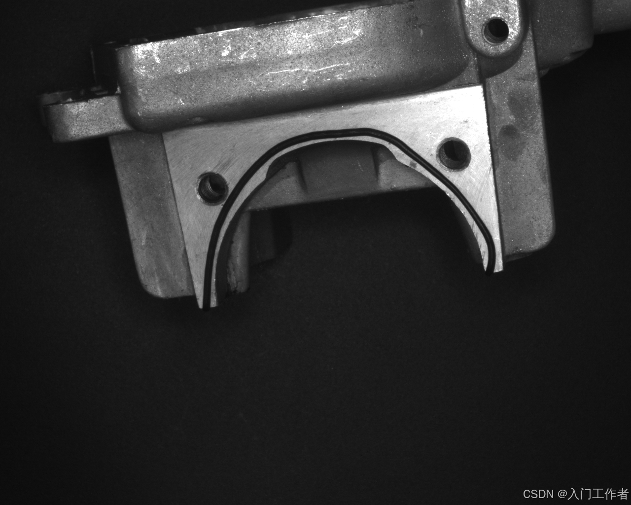
一、检测背景
halcon有例程讲解如何检测胶路缺陷,例如是否断胶、偏移、过窄、过宽等(apply_bead_inspection_model.hdev)
思考:
1.胶路一般有别去背景,可直接二值化提取;
2.胶路检测轨迹复杂不固定,可手动绘制点集,分成N多直线段进行检测;
3.胶路有检测范围,其实是围绕胶路宽度做判断;
4.胶路宽度检测,可将N段直线段提取所有(或等距)的路径点,在路径点的法线方向寻找胶路边缘,一个路径点对应一对胶路边缘;
5.判断逻辑,将没有找到胶路边缘的,说明偏移或断胶报错;胶路边缘可做宽度OK NG判别。
二、代码实现(demo)
cpp
#include <iostream>

#include <opencv2/opencv.hpp>
using namespace cv;
using namespace std;


// 向量归一化
Point2f normalizeVec(Point2f v) {
    float L = sqrt(v.x * v.x + v.y * v.y);
    return L < 1e-6 ? Point2f(0, 0) : Point2f(v.x / L, v.y / L);
}


// 输入:参考路径 + 偏移距离(单边)
// 输出:left_pts 左偏移点集  +  right_pts 右偏移点集
void getLeftRightOffsetLine(
    const vector<Point>& ref_path,
    float offset_dist,          // 偏移宽度(比如 20)
    vector<Point>& left_pts,    // 输出:左侧点
    vector<Point>& right_pts    // 输出:右侧点
) {
    left_pts.clear();
    right_pts.clear();
    int n = ref_path.size();
    if (n < 2) return;

    // ====================== 起点 ======================
    Point2f p0 = ref_path[0];
    Point2f p1 = ref_path[1];
    Point2f dir = normalizeVec(p1 - p0);
    Point2f left_norm(-dir.y, dir.x);    // 左法线
    Point2f right_norm = -left_norm;    // 右法线

    left_pts.push_back(Point(cvRound(p0.x + left_norm.x * offset_dist),
        cvRound(p0.y + left_norm.y * offset_dist)));
    right_pts.push_back(Point(cvRound(p0.x + right_norm.x * offset_dist),
        cvRound(p0.y + right_norm.y * offset_dist)));

    // ====================== 中间点 ======================
    for (int i = 1; i < n - 1; i++) {
        Point2f A = ref_path[i - 1];
        Point2f B = ref_path[i];
        Point2f C = ref_path[i + 1];

        Point2f d1 = normalizeVec(B - A);
        Point2f d2 = normalizeVec(C - B);

        Point2f n1(-d1.y, d1.x);
        Point2f n2(-d2.y, d2.x);

        Point2f left_bisec = normalizeVec(n1 + n2);
        Point2f right_bisec = -left_bisec;

        left_pts.push_back(Point(cvRound(B.x + left_bisec.x * offset_dist),
            cvRound(B.y + left_bisec.y * offset_dist)));
        right_pts.push_back(Point(cvRound(B.x + right_bisec.x * offset_dist),
            cvRound(B.y + right_bisec.y * offset_dist)));
    }

    // ====================== 终点 ======================
    p0 = ref_path[n - 2];
    p1 = ref_path[n - 1];
    dir = normalizeVec(p1 - p0);
    left_norm = Point2f(-dir.y, dir.x);
    right_norm = -left_norm;

    left_pts.push_back(Point(cvRound(p1.x + left_norm.x * offset_dist),
        cvRound(p1.y + left_norm.y * offset_dist)));
    right_pts.push_back(Point(cvRound(p1.x + right_norm.x * offset_dist),
        cvRound(p1.y + right_norm.y * offset_dist)));
}

void main()
{
   const int number = 18;
	//手动输入胶路中心线经过的点
	int x[number] = { 419, 424, 436, 447, 466, 492, 518, 560, 570,580, 602, 752, 809, 915, 978, 994,997,994 };
	int y[number] = { 614, 535, 476, 443, 408, 369, 338, 303, 297,292, 283, 268, 292, 378, 461, 491 ,527,544};

	Mat src = imread("C:\\Users\\Public\\Documents\\MVTec\\HALCON-18.11-Progress\\examples\\images\\bead\\adhesive_bead_01.png", 0);
	Mat dst;
	cvtColor(src, dst, COLOR_GRAY2BGR);
	vector<Point> ref_path;
	for (int i = 0; i < 16; i++)
	{
        ref_path.push_back(Point(x[i], y[i]));
		circle(dst, Point(x[i], y[i]), 1,Scalar(0, 0, 255));
	}
    // ==========================================
   // 3. 生成允许的胶通道(左偏移、右偏移)
   // 对应 Halcon:设定胶宽度 + 公差
   // ==========================================
    int TargetWidth = 14;       // 标准胶宽
    int WidthTolerance = 7;        // 胶宽允许误差
    int PositionTolerance = 30;

#pragma region 其实只是为了绘制
    vector<Point> ref_left_path, ref_right_path;
    getLeftRightOffsetLine(ref_path, TargetWidth / 2, ref_left_path, ref_right_path);

    vector<Point> left_path, right_path;
    getLeftRightOffsetLine(ref_path, PositionTolerance, left_path, right_path);
    for (int i = 0; i < left_path.size(); i++)
    {
        circle(dst, left_path[i], 1, Scalar(0, 255, 0));
        circle(dst, right_path[i], 1, Scalar(255, 0, 0));
    }
    // 拼接成闭合区域(允许的胶带 mask)
    vector<Point> mask_pts = right_path;
    reverse(left_path.begin(), left_path.end());
    mask_pts.insert(mask_pts.end(), left_path.begin(), left_path.end());
    // 拼接成标准胶路区域
    vector<Point> ref_mask_pts = ref_right_path;
    reverse(ref_left_path.begin(), ref_left_path.end());
    ref_mask_pts.insert(ref_mask_pts.end(), ref_left_path.begin(), ref_left_path.end());


    Mat allow_mask = Mat::zeros(src.size(), CV_8UC1);
    vector<vector<Point>> pts;
    pts.push_back(mask_pts);
    fillPoly(allow_mask, pts, Scalar(255));
    pts.push_back(ref_mask_pts);
    drawContours(dst, pts, 0, Scalar(255, 255, 0));
    drawContours(dst, pts, 1, Scalar(0, 255, 0));
#pragma endregion


    Mat src2 = imread("C:\\Users\\Public\\Documents\\MVTec\\HALCON-18.11-Progress\\examples\\images\\bead\\adhesive_bead_05.png", -1);
    medianBlur(src2, src2, 3);
    //为了把实际图平移旋转到标准图
    vector<Point> ref_points, actual_points;
    ref_points.push_back(Point(405, 624));
    ref_points.push_back(Point(1020, 546));
    actual_points.push_back(Point(308,757));
		actual_points.push_back(Point(927,774));
    Mat M = estimateAffinePartial2D(actual_points, ref_points); //4自由度,只有平移旋转和均匀缩放
    Mat aligned;
    warpAffine(src2, aligned, M, src2.size());
    Mat dst2;
    cvtColor(aligned, dst2, COLOR_GRAY2BGR);
    drawContours(dst2, pts, 0, Scalar(255, 255, 0));
    drawContours(dst2, pts, 1, Scalar(0, 255, 0));


    //vector<Point> actual_path;
    //Mat M_inv;
    //invertAffineTransform(M, M_inv);
    //transform(ref_path, actual_path, M_inv);
    for (int i = 0; i < ref_path.size(); i++)
    {
        circle(dst2, ref_path[i], 1, Scalar(0, 0, 255));
    }
    Mat binary;
    threshold(aligned, binary, 70, 255, THRESH_BINARY); //将胶路二值化
    Mat element;
    element = getStructuringElement(MorphShapes::MORPH_RECT, Size(3, 3));
    morphologyEx(binary, binary, MorphTypes::MORPH_CLOSE, element);
    Mat mask;
    binary.copyTo(mask, allow_mask);


    vector<float> widths;

    for (int i = 0; i < ref_path.size(); i++)//遍历胶路中的选中点,在每个点处的法线方向进行遍历,寻找胶路的宽度值
    {
        Point p = ref_path[i];
        Point2f dir;
        if (i == 0) {  //在第一个点和最后一个点的时候,法线方向与中间点不同
            dir = ref_path[1] - ref_path[0];
        }
        else if (i == ref_path.size() - 1) {
            dir = ref_path[ref_path.size() - 1] - ref_path[ref_path.size() - 2];
        }
        else {
            dir = ref_path[i + 1] - ref_path[i - 1];
        }
        // 归一化
        float len = norm(dir);
        dir.x /= len;
        dir.y /= len;

        float w = 0;
        Point first_whiteTOblack_pt;
        bool first_whiteTOblack = false;
        bool find_bead = false;
        // 旋转90度 → 法线方向,单位向量直接改变取反Y或者X,就是旋转90度
        Point2f normal(-dir.y, dir.x);
        for (int t = -PositionTolerance+1; t < PositionTolerance; t++)//对法线方向像素点进行遍历
        {
            int x = cvRound(ref_path[i].x + normal.x * t);
            int y = cvRound(ref_path[i].y + normal.y * t);
            int prev_x = cvRound(ref_path[i].x + normal.x * (t - 1));
            int prev_y = cvRound(ref_path[i].y + normal.y * (t - 1));
            //circle(dst2, Point(x,y), 1, Scalar(255, 255, 255));
            uchar pix = mask.at<uchar>(y, x);
            uchar prev_pix = mask.at<uchar>(prev_y, prev_x);

            if (!first_whiteTOblack && pix == 0 && prev_pix == 255) {
                first_whiteTOblack = true;
                first_whiteTOblack_pt = Point(x, y);
                circle(dst2, first_whiteTOblack_pt, 5, Scalar(255, 255, 255));
            }
            Point end_pt;
            if (first_whiteTOblack && pix == 255 && prev_pix == 0){
                end_pt = Point(x, y);
                circle(dst2, end_pt, 5, Scalar(255, 255, 255));
                w = norm(end_pt - first_whiteTOblack_pt);
                if (w < TargetWidth - WidthTolerance) {
                    putText(dst2, "too thin", Point(x, y), HersheyFonts::FONT_HERSHEY_COMPLEX, 1, Scalar(0, 0, 255));
                }
                else if (w > TargetWidth + WidthTolerance) {
                    putText(dst2, "too thick", Point(x, y), HersheyFonts::FONT_HERSHEY_COMPLEX, 1, Scalar(0, 0, 255));
                }
                widths.push_back(w);
                find_bead = true;
                break;
            }

        }
        if (!first_whiteTOblack || (first_whiteTOblack && !find_bead))
        {
            putText(dst2, "error", p, HersheyFonts::FONT_HERSHEY_COMPLEX, 1, Scalar(0, 0, 255));
        }


    }

}
检测效果如下:
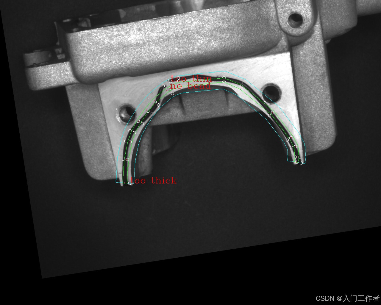
三、代码分析
0.代码中手动选取两张图片的对应点做的仿射,实际工程中可以找两mark,或者直接模板匹配将目标图和参考图对齐
1.绘制的点数可以适当增加,使直线段更贴合胶路轨迹
2.我只做了绘制点处的胶宽检测,实际应该用LineIterator line_iter(src, startP, endP, 8);获取两点之间的所有点,进行法线方向的胶宽检测
3.针对二值化后轮廓不明确,有干扰的情况,我认为应该将干扰位置提前涂白(比如螺丝孔、产品外面背景位置等),仿射变换之后就可以先涂白,然后进行二值化
4.针对硬二值化效果不好,可以在法线方向进行直线卡尺,直接获取胶路轮廓
5.后续就是判断逻辑,比如平均值低于(或高于)多少也是不良,连续窄胶宽也报警等逻辑
本人没实际做点胶项目,有实际项目或同行可私信交流