一、基础架构
三层模型(3-tier model)
充电桩(Charging Station)→ EVSE → 连接器(Connector)
逻辑分层,不强制对应物理硬件
信息模型 vs 设备模型
信息模型 :协议报文与数据类型的底层结构(CIM/CEFACT)
设备模型:通用管理机制,让任意充电桩可被平台统一配置、监控、上报结构
二、设备模型(核心)
组件(Component)
代表物理 / 逻辑模块:ChargingStation、EVSE、Connector、控制器、风扇、电表等
用名称 + 实例 + EVSE/Connector ID 定位
变量(Variable)
组件的数据载体:配置、测量值、状态
支持多实例,用 variableInstance 区分
特性与属性
特性(只读):单位、数据类型、上下限
属性(读写):实际值、目标值、可变性、持久化
监控(Monitoring)
类型:上限 / 下限阈值、差值、周期、时钟对齐周期
数值 / 整型支持阈值;所有类型支持差值 / 周期
触发后更新基准值;周期单位为秒
标准化与最小实现
组件 / 变量用标准名,未定义可自定义并反馈给 OCA
必实现:SetVariables、GetVariables、GetBaseReport(配置 / 全量清单)
监控相关报文均为可选,推荐实现 NotifyEvent
三、编号规则(强制规范)
EVSE 编号
从 1 开始连续不跳号;ID≤总数
evseId=0:平台指令 = 整桩;设备上报 = 主控
连接器编号
每个 EVSE 下从 1 开始连续不跳号
交易 ID(TransactionId)
OCPP2.0.1 由充电桩生成,桩内唯一;支持自增 / UUID
四、支持的 6 种组网拓扑
直连模式:桩 ↔ CSMS(基础)
本地代理(LP):仅转发报文,桩 / 平台互相无感知
本地控制器(LC):可脱离平台独立控桩(本地智能充电),LC 视为虚拟桩
非 OCPP 桩适配:LC 做协议转换,模拟成 OCPP 桩
配电网调度(DSO):DSO 给平台信号,平台统一控桩
并行控制:CSMS+EMS 同时管控,桩把 EMS 限值上报平台
五、扩展用途
OCPP 不只用于充电,还可管理变压器、电池等设备
无顶层 ChargingStation 组件即可识别为非充电设备
六、信息模型(附录)
基于 UML+CIM,分业务域:交易、智能充电、计量、安全、通信、二次调度
报文生成三步:模型→消息简化→替换为基础数据类型
OCPP 2.0.1 Part 1 Architecture & Topology(AI翻译)
原版页码:0
原文
OCPP OCPP 2.0.1 Part 1 - Architecture & Topology Edition 4, 2025-12-03
Table of Contents
Disclaimer......1
Version History.......2
1.Introduction.......3
1.1. Goal of this document.........3
1.2. Terms and abbreviations........3
2.3-tier model..... 4
3.Information Model........5
4.Device Model: Addressing Components and Variables......6
4.1.Components......6
4.2. Variables......7
4.3. Characteristics and Attributes....7
4.4. Monitoring...9
4.5. Standardized lists of Components and Variables......10
4.6. Minimum Device Model...........10
5.Information Model vs. Device Model..................................................................12
6.Using OCPP for other purposes than EV charging.......... 13
7.Numbering ..........14
7.1.EVSE numbering.....14
7.2.Connector numbering.......14
7.3. Transaction IDs...........14
8.Topologies supported by OCPP...............15
8.1. Charging Station(s) directly connected to CSMS.......15
8.2. Multiple Charging Stations connected to CSMS via Local Proxy...................................................15
8.3. Multiple Charging Stations connected to CSMS via Local Controller ............................15 8.4. Non-OCPP Charging Stations connected to CSMS via OCPP Local Controller.......................................16
8.5.DSO control signals to CSMS............................16
8.6. Parallel control by CSMS and EMS.......16
9.Part 1 Appendix: OCPP Information Model........18
9.1. Explanation of UML representation and message generation.......18
9.2. Visual Representation of OCPP Information Model......................................... .............19
译文
OCPP OCPP 2.0.1 第 1 部分 - 架构与拓扑 版本 4,2025 年 12 月 03 日
目录
免责声明......1
版本历史.......2
- 引言.......3
1.1. 本文档目标.........3
1.2. 术语和缩写........3
-
三层模型.....4
-
信息模型........5
-
设备模型:组件与变量寻址......6
4.1. 组件......6
4.2. 变量......7
4.3. 特征与属性....7
4.4. 监控...9
4.5. 组件与变量标准化清单......10
4.6. 最小设备模型...........10
-
信息模型与设备模型对比..................................................................12
-
将 OCPP 用于电动汽车充电以外的用途..........13
-
编号规则..........14
7.1.EVSE 编号.....14
7.2. 连接器编号.......14
7.3. 交易 ID...........14
8.OCPP 支持的拓扑结构...............15
8.1. 充电桩直接连接至 CSMS.......15
8.2. 多充电桩通过本地代理连接至 CSMS...................................................15
8.3. 多充电桩通过本地控制器连接至 CSMS............................15
8.4. 非 OCPP 充电桩通过 OCPP 本地控制器连接至 CSMS.......................................16
8.5. 配电网运营商向 CSMS 发送控制信号............................16
8.6.CSMS 与 EMS 并行控制.......16
- 第 1 部分附录:OCPP 信息模型........18
9.1.UML 表示与报文生成说明.......18
9.2.OCPP 信息模型可视化表示......................................... .............19
原版页码:1
原文
Disclaimer
Copyright © 2010 -- 2025 Open Charge Alliance. All rights reserved.
This document is made available under the *Creative Commons Attribution-NoDerivatives 4.0 International Public License* (https://creativecommons.org/licenses/by-nd/4.0/legalcode).
译文
免责声明
版权所有 ©2010-2025 开放充电联盟。保留所有权利。
本文档依据知识共享署名 - 禁止演绎 4.0 国际公共许可证 提供(https://creativecommons.org/licenses/by-nd/4.0/legalcode)。
原版页码:2
原文
Version History
|-----------------|------------|----------------------------------------------------------------------------------------------------------------------------------------------------------------|
| Version | Date | Description |
| 2.0.1 Edition 4 | 2025-12-03 | 2025-12-03 OCPP 2.0.1 Edition 4. All errata from OCPP 2.0.1 Part 0 until and including Errata 2025-11 have been merged into this version of the specification. |
| 2.0.1 Edition 3 | 2024-05-06 | OCPP 2.0.1 Edition 3. All errata from OCPP 2.0.1 Part 0 until and including Errata 2024-04 have been merged into this version of the specification. |
| 2.0.1 | 2020-03-31 | Final version of OCPP 2.0.1 |
| 2.0 | 2018-04-11 | OCPP 2.0 April 2018 First release of this Introduction document |
译文
版本历史
|------------|------------------|--------------------------------------------------------------------|
| 版本 | 日期 | 说明 |
| 2.0.1 版本 4 | 2025 年 12 月 03 日 | OCPP 2.0.1 版本 4。已将 OCPP 2.0.1 第 0 部分截至 2025 年 11 月(含)的所有勘误合并至本版规范。 |
| 2.0.1 版本 3 | 2024 年 05 月 06 日 | OCPP 2.0.1 版本 3。已将 OCPP 2.0.1 第 0 部分截至 2024 年 4 月(含)的所有勘误合并至本版规范。 |
| 2.0.1 | 2020 年 03 月 31 日 | OCPP 2.0.1 最终版本 |
| 2.0 | 2018 年 04 月 11 日 | OCPP 2.0 2018 年 4 月 本引言文档首次发布 |
原版页码:3
原文
Chapter 1. Introduction
1.1. Goal of this document
The goal of this document is to describe a number of architecture related topics for OCPP 2.0.1 .
OCPP was originally intended for two way communication between a backoffice, in OCPP the Charging Station Management System (in this document: CSMS) and a Charging Station. The protocol has become more advanced and with every new revision new functionalities and options are added. It has evolved into a protocol that can be used in different architectures for different types of Charging Stations.
This document describes, in addition to the original "simple" setup CSMS <> Charging Station, a number of topologies as an additional explanation for using OCPP. Furthermore, the Device Management concept to configure and monitor any type of Charging Station, the OCPP Information Model and the 3-tier model are explained.
This document is partially informative and partially normative and is not intended to limit the use of OCPP. However, it does add an explanation what kind of use of OCPP the creators of OCPP had in mind when creating this version of the specification. This document is therefore also intended to support the reader of the protocol specification in Part 2 of OCPP to understand how it can be used.
1.2. Terms and abbreviations
This section contains the terminology and abbreviations that are used throughout this document.
1.2.1. Terms
|------------------------|-------------------------------------------------------------------------------------------------------------------------------------------------------------------------------------------------------------------------------------------------------------------------------------------------------------------------------------------------------------------------------------------------------------------------------|
| Term | Meaning |
| Charging Station | The Charging Station is the physical system where EVs can be charged. A Charging Station has one or more EVSEs. |
| Connector | The term Connector, as used in this specification, refers to an independently operated and managed electrical outlet on a Charging Station. In other words, this corresponds to a single physical Connector. In some cases an EVSE may have multiple physical socket types and/or tethered cable/Connector arrangements(i.e. Connectors) to facilitate different vehicle types (e.g. four-wheeled EVs and electric scooters). |
| EVSE | An EVSE is considered as an independently operated and managed part of the Charging Station that can deliver energy to one EV at a time. |
| Local port Smart Meter | The local port on a Smart Meter is a port (for example serial) on a digital electricity meter that provides access to information about meter readings and usage. |
1.2.2. Abbreviations
|--------------|--------------------------------------------------------------------------------------------------------------------------------------------------------------------------------------------------------------------------------------------------------------------------------------------------------------------------------------------|
| Abbreviation | Meaning |
| DSO | Distribution System Operator |
| CSO | Charging Station Operator |
| CSMS | Charging Station Management System |
| EMS | Energy Management System. In this document this is defined as a device that manages the local loads (consumption an production) based on local and/or contractual constraints and/or contractual incentives. It has additional inputs, such as sensors and controls from e.g. PV, battery storage. |
| EVSE | Electric Vehicle Supply Equipment LC Local Controller. |
| LC | Local Controller.In this document this is defined as a device that can send messages to its Charging Stations, independently of the CSMS. A typical usage for this is the local smart charging case described in the Smart Charging chapter of Part 2 of OCPP, where a Local Controller can impose charge limits on its Charging Stations. |
| LP | Local Proxy. Acts as a message router. |
译文
第 1 章
引言
1.1. 本文档目的
本文档旨在阐述与 OCPP 2.0.1 相关的若干架构主题。
OCPP 最初用于后台系统(在 OCPP 中称为充电桩管理系统,本文中简称 CSMS)与充电桩之间的双向通信。该协议已愈发完善,每个新版本都会增加新功能与新选项,现已发展为可在不同架构下为不同类型充电桩提供服务的协议。
除了最初 CSMS 与充电桩直连的基础部署方式外,本文档还描述了多种可使用 OCPP 的拓扑结构以作补充说明。此外,本文档还阐述了用于对各类充电桩进行配置与监控的设备管理概念、OCPP 信息模型以及三层模型。
本文档部分内容为说明性,部分为规范性,不旨在限制 OCPP 的使用。但它补充说明了 OCPP 制定者在编写本版规范时所期望的 OCPP 使用方式。因此,本文档也用于帮助阅读 OCPP 第 2 部分协议规范的读者理解其应用方式。
1.2. 术语与缩写
本节包含本文档通篇使用的术语与缩写。
1.2.1. 术语
|----------|-----------------------------------------------------------------------------------------------------------------------------|
| 术语 | 含义 |
| 充电桩 | 可供电动汽车充电的物理系统,一台充电桩包含一个或多个 EVSE。 |
| 连接器 | 本规范所使用的 "连接器" 一词,指充电桩上可独立操作与管理的供电接口,即对应一个物理连接器。在部分场景下,一个 EVSE 可具备多种物理接口类型和 / 或线缆 / 连接器配置(即多个连接器),以适配不同车型(例如四轮电动汽车与电动轻便摩托车)。 |
| EVSE | EVSE 指充电桩中可独立操作与管理、且一次仅能为一辆电动汽车供电的部分。 |
| 智能电表本地端口 | 智能电表的本地端口是数字电表上的一种端口(如串口),用于获取电表读数与用电相关信息。 |
1.2.2. 缩写
|------|------------------------------------------------------------------------------------------------|
| 缩写 | 含义 |
| DSO | 配电系统运营商 |
| CSO | 充电桩运营商 |
| CSMS | 充电桩管理系统 |
| EMS | 能源管理系统。在本文档中定义为:基于本地及 / 或合同约束、合同激励机制管理本地负荷(消耗与生产)的设备。该系统具备额外输入接口,例如来自光伏、储能系统的传感器与控制信号。 |
| EVSE | 电动汽车供电设备 |
| LC | 本地控制器。在本文档中定义为:可独立于 CSMS 向其下属充电桩发送消息的设备。典型应用场景为 OCPP 第 2 部分智能充电章节所述的本地智能充电方案,本地控制器可向充电桩下发充电限制。 |
| LP | 本地代理。充当消息路由器。 |
原版页码:4
原文
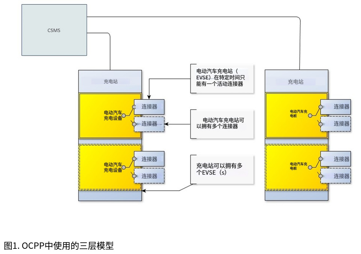
Chapter 2. 3-tier model
This section is informative.
To understand the terminology in the OCPP specification, it is important to understand the starting point of this specification. The OCPP specification uses the term Charging Station as the physical system where EVs can be charged. A Charging Station can have one or more EVSEs (Electric Vehicle Supply Equipment). An EVSE is considered as a part of the Charging Station that can deliver energy to one EV at a time. The term Connector, as used in this specification, refers to an independently operated and managed electrical outlet on a Charging Station, in other words, this corresponds to a single physical Connector. In some cases an EVSE may have multiple physical socket types and/or tethered cable/connector arrangements to facilitate different vehicle types (e.g. four wheeled EVs and electric scooters). This setup is referred to as the 3-tier model and visualized in the figure below.
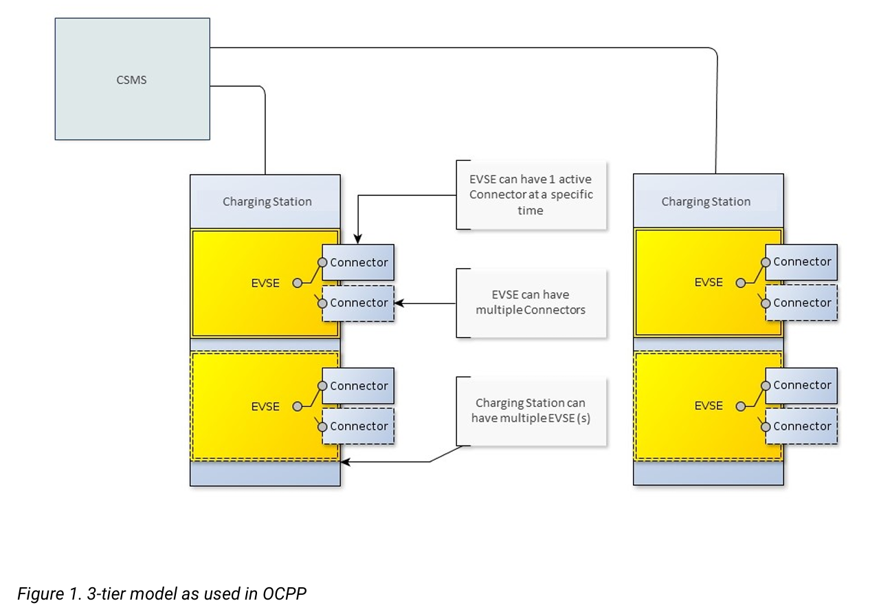
Note
This section describes the charging infrastructure on a logical level for communication purposes. We do not wish to impose a mapping onto physical hardware. This is a manufacturer's choice. For example, the EVSE might be integrated into a Charging Station and to look as just a part of that device, but it might just as well have its own casing and live outside of the physical entity Charging Station, for example a charging plaza with 20 EVSEs and Connectors which communicates via 1 modem as 1 Charging Station to the CSMS is seen by OCPP as 1 Charging Station.
译文
第 2 章 三层模型
本节为说明性内容。
要理解 OCPP 规范中的术语,必须先明确本规范的基础定义。OCPP 规范将充电桩 定义为可供电动汽车充电的物理系统,一台充电桩可包含一个或多个 EVSE(电动汽车供电设备)。EVSE 是充电桩中可同时为一辆电动汽车提供电能的组成部分。本规范中使用的连接器 一词,指充电桩上可独立操作与管理的供电接口,即对应一个物理连接器。在部分场景下,一个 EVSE 可具备多种物理接口类型和 / 或线缆 / 连接器配置,以适配不同车型(例如四轮电动汽车与电动两轮车)。该结构被称为三层模型,如下图所示。
注:
本节从通信逻辑层面描述充电基础设施,无意强制要求其与物理硬件形成映射关系,具体实现由厂商自行决定。例如,EVSE 可集成在充电桩内部,作为设备的一部分;也可拥有独立外壳,部署在充电桩物理实体之外。如一个包含 20 台 EVSE 及连接器的充电广场,通过一台调制解调器作为单个充电桩与 CSMS 通信,在 OCPP 中会被视为一个充电桩。
原版页码:5
原文
Chapter 3. Information Model
This section is informative. Given the growing complexity of the messages of OCPP, OCPP 2.0.1 is based on an Information Model as a blueprint for the messages and inherent schemas of OCPP. With an information model, we mean a logical object set, describing real objects with all their properties. This provides an informative representation of information structure in the protocol. Furthermore, it enables making objects within OCPP reusable and enables consistent definition of messages and automatically generated message schemas (Part 3).
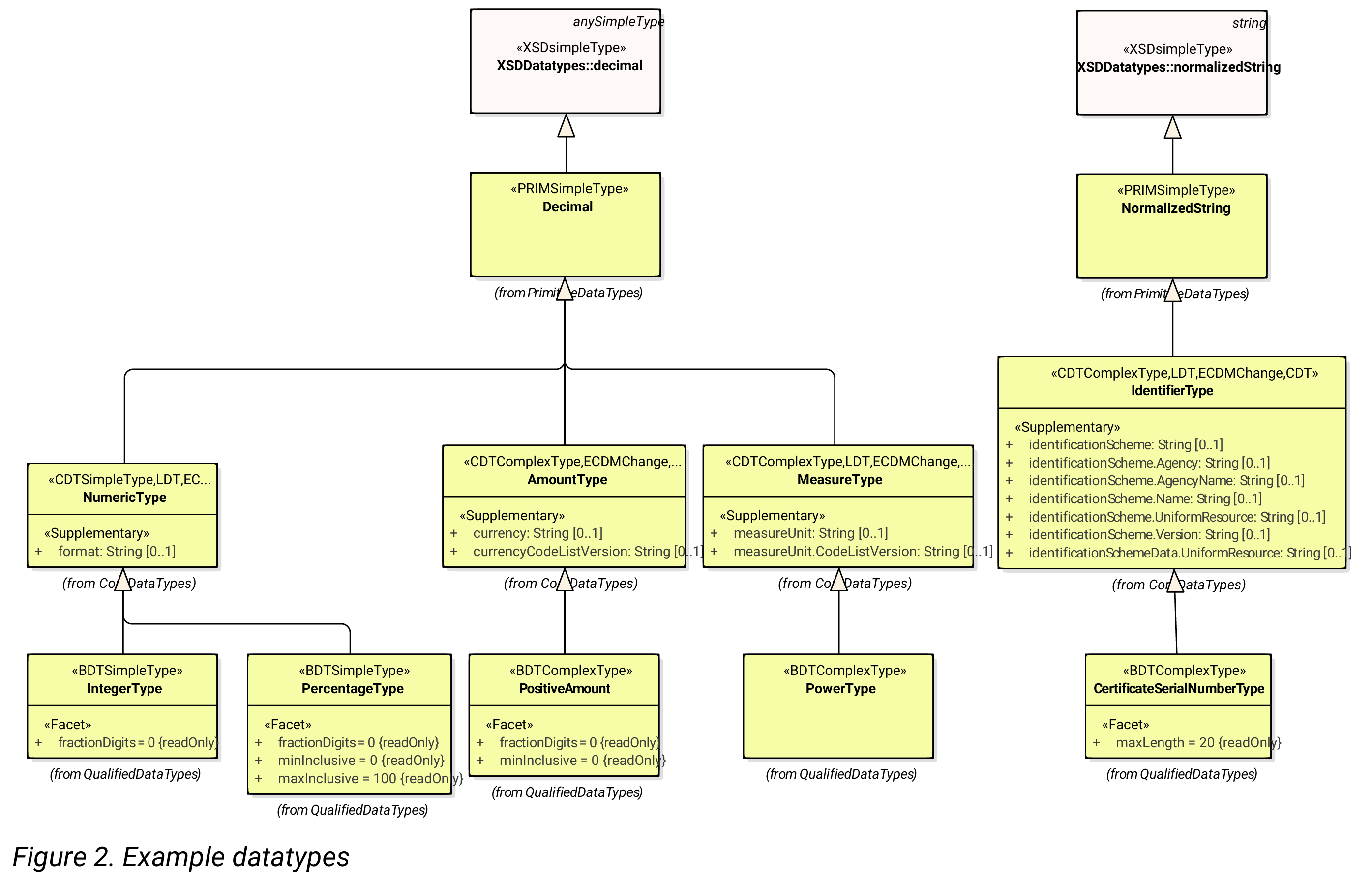
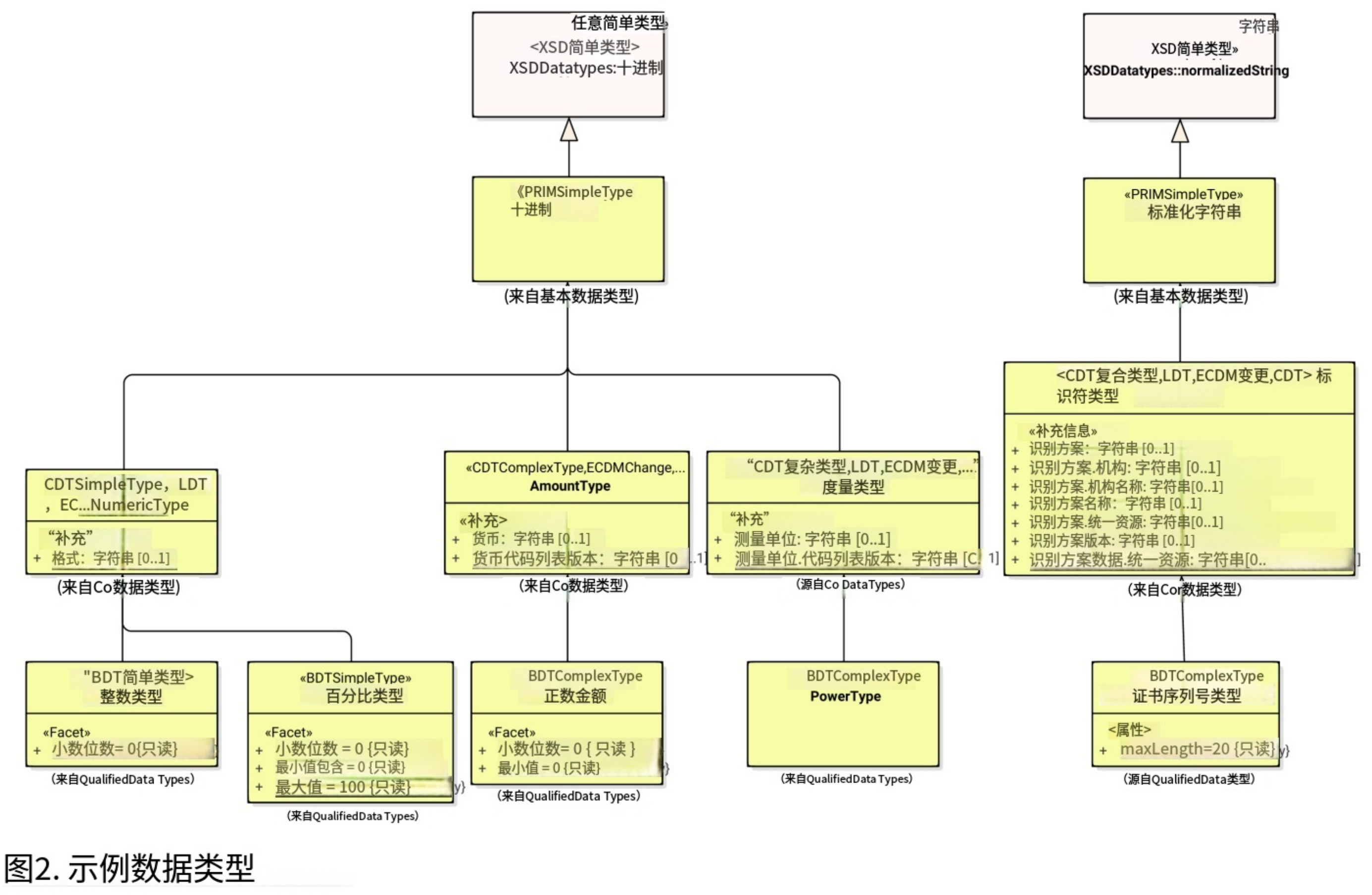
The Information Model is a model, also called Domain Model or Core Model, based on which the OCPP messages and datatypes are generated. These datatypes are extracted from the the OCPP 1.6 specification and are named Core DataTypes and Qualified DataTypes. The figure below illustrates how the DataTypes in the information model are built up.
In part 2 - Specification, chapter Datatypes, some DataTypes have the Common: prefix. This originates from the Information Model. It means that the DataType is able to be shared among other DataTypes and Messages. This has no impact on the OCPP implementation of a device.
The Information Model is divided into a number of "functions" to have a better overview of the model (thus for readability):
• Transactions
• SmartCharging
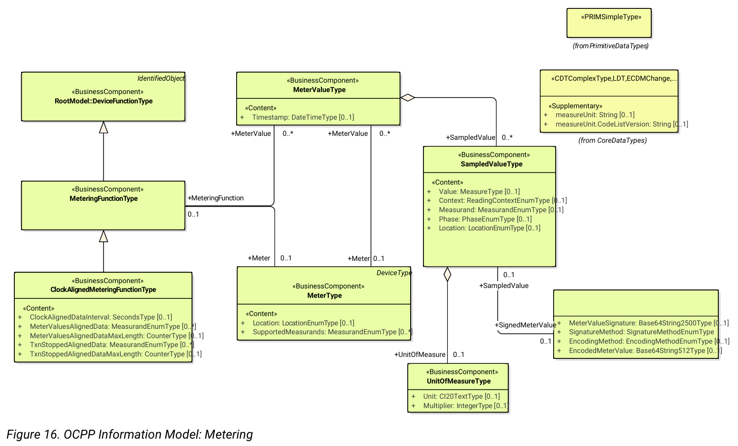
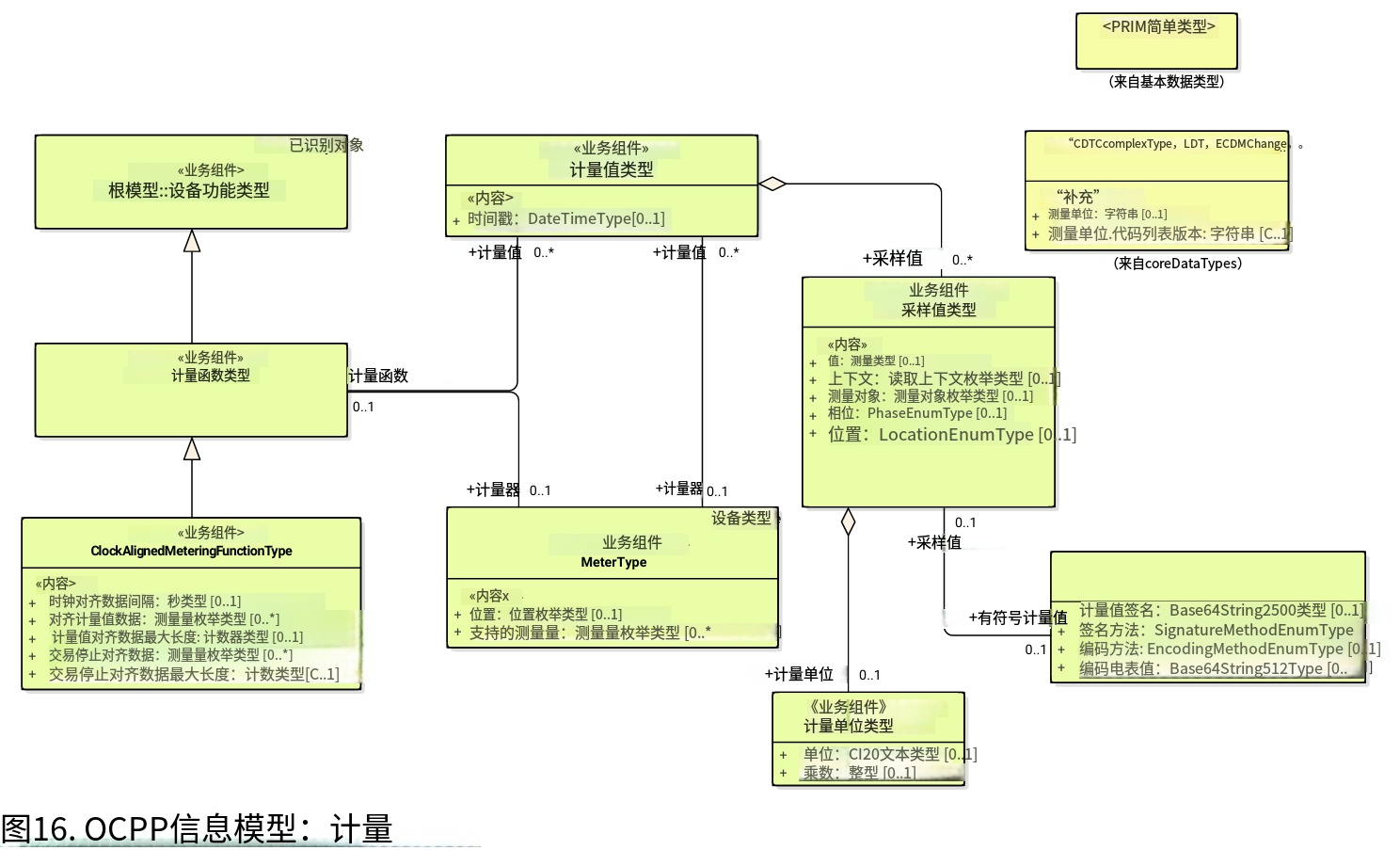
• Metering
• Security (Profiles/Authorization)
• Communication
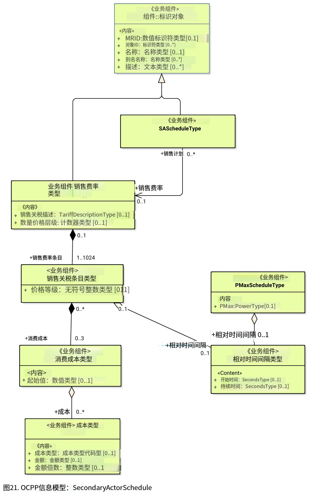
• SecondaryActorSchedule
For more details about the actual model per function, please refer to the appendix.
译文
第 3 章 信息模型
本节为说明性内容。随着 OCPP 报文复杂度不断提升,OCPP 2.0.1 以信息模型作为报文及其内置模式的设计蓝图。信息模型是指一套逻辑对象集合,用于描述真实对象及其全部属性,为协议中的信息结构提供说明性表达。同时,它可实现 OCPP 内部对象的复用,支持报文的一致性定义并可自动生成报文模式(第 3 部分)。
信息模型也称为领域模型或核心模型,OCPP 报文与数据类型均基于该模型生成。此类数据类型提取自 OCPP 1.6 规范,分为核心数据类型与限定数据类型。下图展示了信息模型中数据类型的构建方式。
在第 2 部分规范的数据类型章节中,部分数据类型带有 Common: 前缀,该前缀来源于信息模型,表示该数据类型可在其他数据类型与报文之间共享,不会对设备的 OCPP 实现产生影响。
为便于概览模型(提升可读性),信息模型划分为多个 "功能模块":
・交易
・智能充电
・计量
・安全(配置文件 / 授权)
・通信
・第三方角色计划
有关各功能模块实际模型的更多细节,请参阅附录。
原版页码:6
原文
Chapter 4. Device Model: Addressing Components and Variables
The Device Model refers to a generalized mechanism within OCPP to enable any model of Charging Station to report how it is build up, so it can be managed from any CSMS. To manage a Charging Station with the Device Model (i.e. "to manage a device") a number of messages and use cases is defined to configure and monitor a Charging Station in detail, without defining the structure of the Charging Station in advance. To be able do do this, OCPP provides a generalized mechanism to allow the exchange of a wide range of information about Charging Station. This version of the Device Model has the 3-tier model (Charging Station, EVSE, Connector) as its starting point, which means that any description created with the Device Model follows these three tiers. The remainder of this chapter describes how the data (and associated meta-data) looks like that can be exchanged between a Charging Station and a CSMS. The use cases and messages that are used to manage a device are not described here, but in Part 2 of the specification. This chapter only focuses on the data model.
4.1. Components
In OCPP 2.0.1 , a Charging Station is modelled as a set of "Components", typically representing physical devices (including any external equipment to which it is connected for data gathering and/or control), logical functionality, or logical data entities.
Components of different types are primarily identified by a ComponentName, that is either the name of a standardized component (see OCPP part 2c), or a custom/non-standardized component name, for new, pre-standardized equipment, vendor specific
extensions, etc.
ChargingStation (TopLevel), EVSE, and Connector represent the three major "tiers" of a Charging Station, and constitute an implicit "location-based" addressing scheme that is widely used in many OCPP data structures. Each "tier" has a component of the same name, which represents the tier.
For example, EVSE 1 on a Charging Station is represented by the component named "EVSE" (no instance name) with "evseId = 1". In the same manner, Connector 1 on EVSE 1 is represented by the component named "Connector" (no instance name) with "evseId = 1, connectorId = 1".
By default, all components are located at the ChargingStation tier, but individual instances of any component can be associated with a specific EVSE, or a specific Connector (on a specific EVSE) by including EVSE or EVSE and Connector identification numbers as part of a component addressing reference.
Additionally, there can be more than one instance of a component (in the functional dimension), representing multi-occurrence physical or logical components (e.g. power converter modules, fan banks, resident firmware images, etc.). Each distinct component instance is uniquely identified by an (optional) componentInstance addressing key. It is allowed for a component to exist without an instance and at the same time also exist with one of more instances. When no componentInstance is provided, then the component without an instance is referenced.
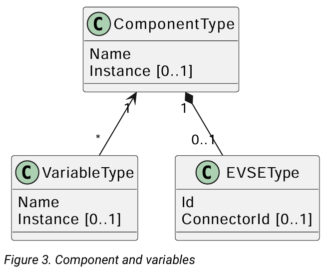
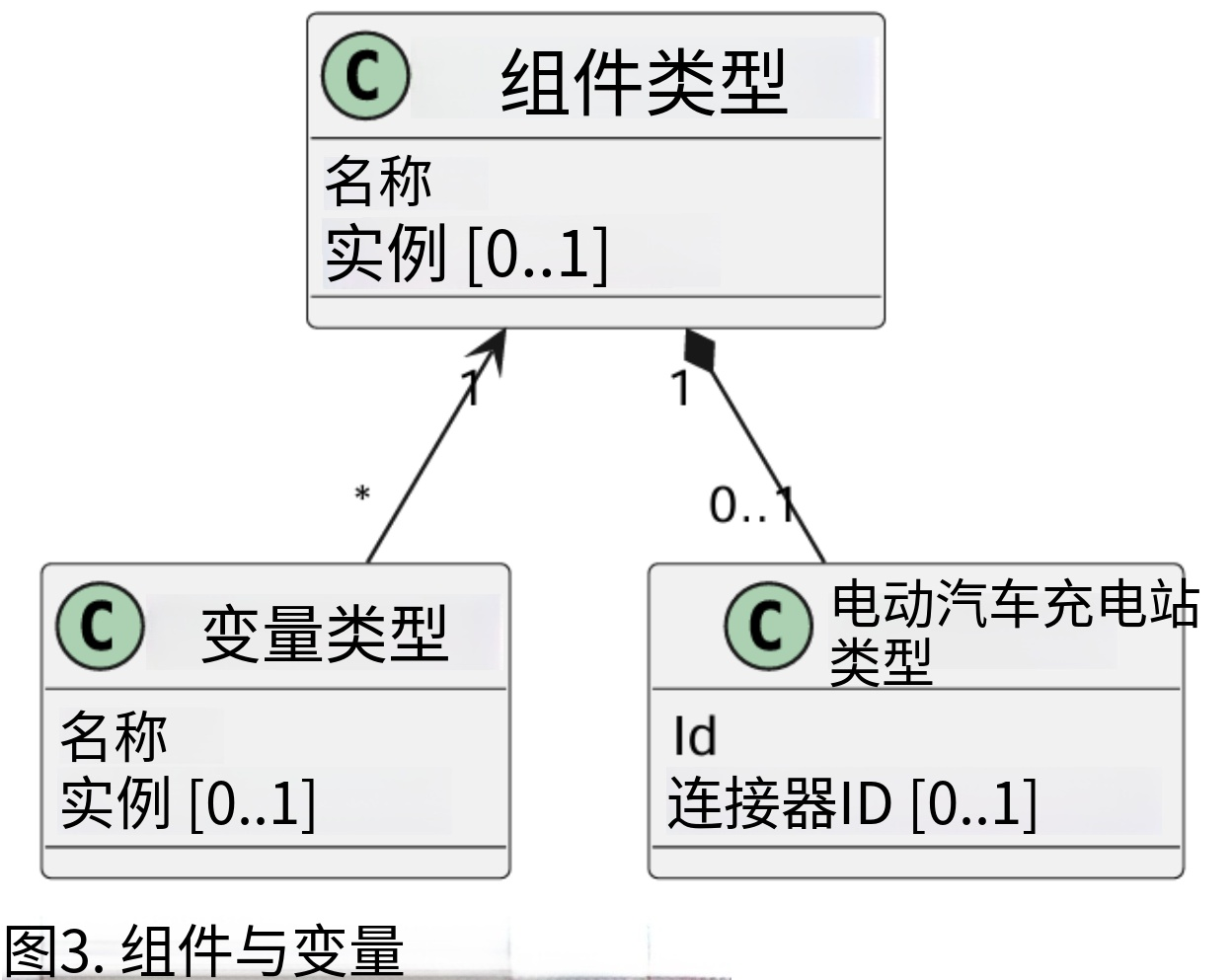
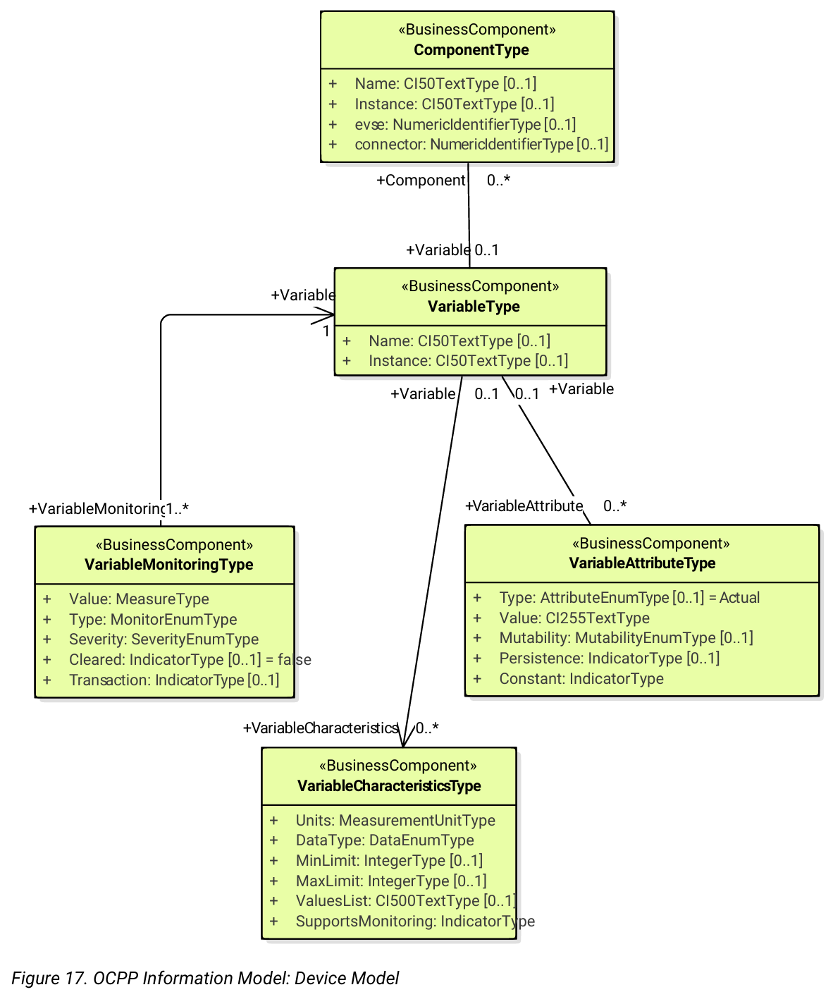
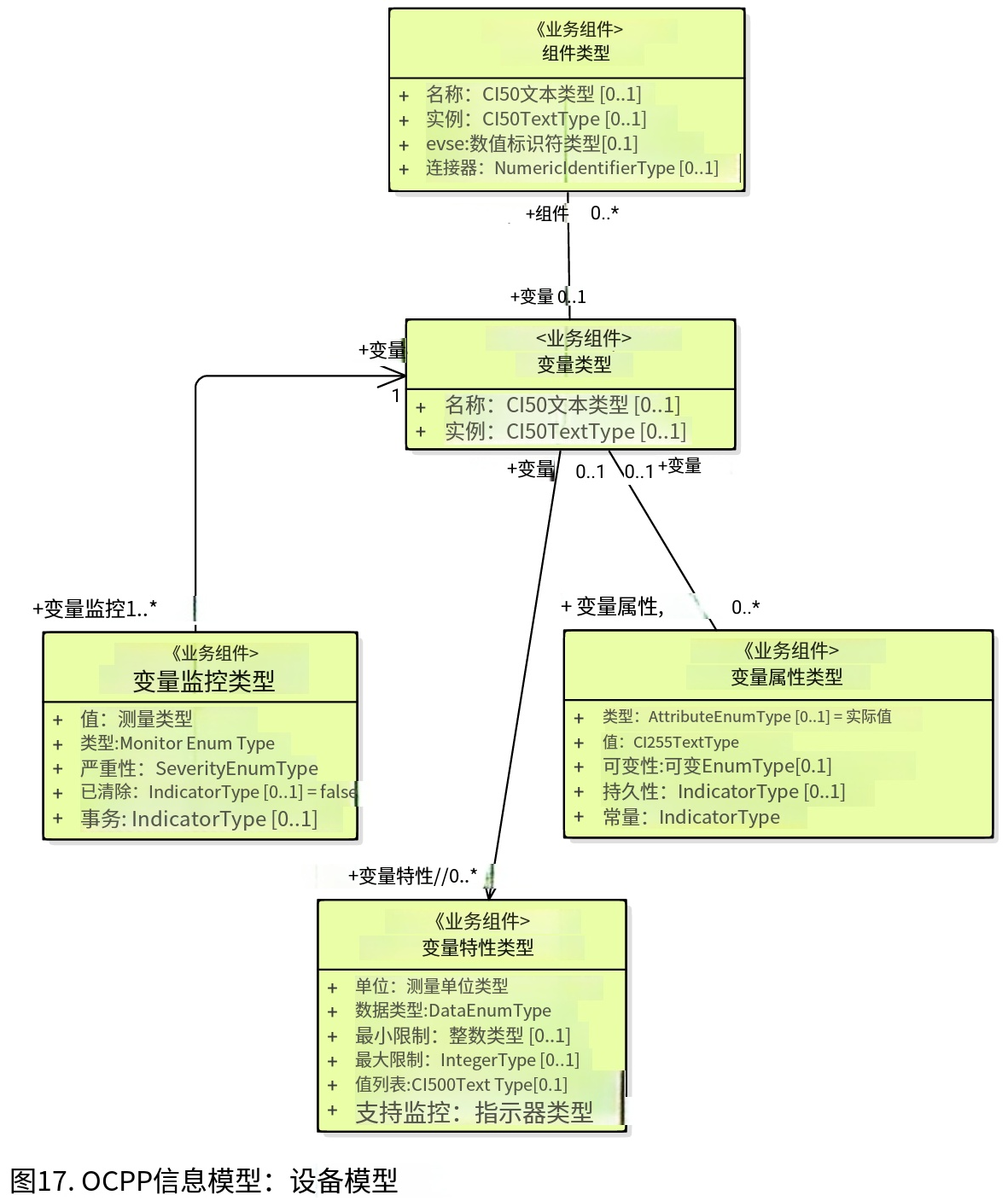
Components do not in themselves hold data: all externally accessible data associated with each component instance is represented by a set of variables that can be read, set, and/or monitored for changes. The relationship of a Component with one or more Variables is illustrated in below.
The table below illustrates some common components (by their standardized component-names), and examples of the hierarchical location levels at which they typically occur for a basic home charger and a typical public Charging Station.
|--------------------------------------|---------------------------|--------------------------------|
| ChargingStation tier | EVSE tie | Connector tier |
| ChargingStation (itself, as a whole) | EVSE (itself, as a whole) | Connector (itself, as a whole) |
[Basic home charger example configuration]
译文
第 4 章 设备模型:组件与变量寻址
设备模型是 OCPP 中的一种通用机制,可使任意型号的充电桩上报自身结构,从而能被任意 CSMS 管理。为通过设备模型管理充电桩(即 "管理设备"),规范定义了一系列报文与用例,用于对充电桩进行精细化配置与监控,而无需预先定义充电桩结构。为实现这一目标,OCPP 提供一套通用机制,用于交换与充电桩相关的各类信息。本版设备模型以三层模型(充电桩、EVSE、连接器)为起点,这意味着通过设备模型创建的所有描述均遵循这三个层级。本章剩余部分描述充电桩与 CSMS 之间可交换的数据(及相关元数据)格式。用于设备管理的用例与报文不在此描述,而在规范第 2 部分中说明。本章仅关注数据模型。
4.1. 组件
在 OCPP 2.0.1 中,充电桩被建模为一组 "组件",组件通常代表物理设备(包括用于数据采集和 / 或控制而连接的任何外部设备)、逻辑功能或逻辑数据实体。
不同类型的组件主要通过组件名称标识,该名称可以是标准化组件名称(参见 OCPP 第 2c 部分),也可以是自定义 / 非标准化组件名称,适用于新型设备、预标准化设备、厂商专属扩展等场景。
充电桩(顶层)、EVSE、连接器代表充电桩的三大主要层级,并构成一种隐式的 "基于位置" 的寻址方案,广泛用于 OCPP 多种数据结构。每个层级均拥有一个同名组件,用于表示该层级。
例如,充电桩上的 EVSE 1 由名称为 "EVSE"(无实例名)且 evseId=1 的组件表示。同理,EVSE 1 上的连接器 1 由名称为 "Connector"(无实例名)且 evseId=1、connectorId=1 的组件表示。
默认情况下,所有组件均位于充电桩层级,但任何组件的单个实例可通过在组件寻址引用中包含 EVSE 编号或 EVSE 及连接器编号,关联到特定 EVSE 或特定(特定 EVSE 上的)连接器。
此外,一个组件可存在多个实例(功能维度),表示重复出现的物理或逻辑组件(如电源转换模块、风扇组、驻留固件镜像等)。每个不同的组件实例由可选的 componentInstance 寻址键唯一标识。允许一个组件同时存在无实例与有一个或多个实例的形态。若未提供 componentInstance,则引用无实例的组件。
组件本身不存储数据:与每个组件实例相关的所有对外可访问数据,均由一组可读取、设置和 / 或监控变化的变量表示。组件与一个或多个变量之间的关系如下所示。
下表列出部分常用组件(采用标准化组件名称),并分别举例说明这些组件在基础家用充电桩与典型公共充电桩中通常所处的层级位置。
|---------|----------|---------|
| 充电桩层级 | EVSE 层级 | 连接器层级 |
| 充电桩(整体) | EVSE(整体) | 连接器(整体) |
[基础家用充电桩典型配置]
原版页码:7
原文
|-------------|-------------------------|-------------------|
| RadioLink | ControlMetering | PlugRetentionLock |
| TokenReader | OverCurrentBreaker | PlugRetentionLock |
| Controller | RCD | |
| | ChargingStatusIndicator | |
[Basic home charger example configuration]
|--------------------------------------|---------------------------|--------------------------------|
| ChargingStation tier | EVSE tier | Connector tier |
| ChargingStation (itself, as a whole) | EVSE (itself, as a whole) | Connector (itself, as a whole) |
| ElectricalFeed | ElectricalFeed | AccessProtection |
| TokenReader | TokenReader | PlugRetentionLock |
| Display | Display | |
| FiscalMetering | FiscalMetering | |
| Clock | ControlMetering | |
| Controller | OverCurrentBreaker | |
| | RCD | |
| | ChargingStatusIndicator | |
[Public Charging Station example configuration]
4.2. Variables
Every component has a number of variables, that can, as appropriate, be used to hold, set, read, and/or report on all (externally visible) data applicable to that component, including configuration parameters, measured values (e.g. a current or a temperature) and/or monitored changes to variable values.
Although many components can have associated variables that are, by their nature, specific to the component type (e.g. ConnectorType for a Connector component), there is a minimal set of standardized variables that is used to provide standardized high level event notification and state/status reporting (e.g. Problem, Active) on a global and/or selective basis, and also to report component presence, availability, etc. during the inventorying/discovery process (e.g. Available, Enabled).
A Charging Station is not required to report the base variables: Present, Available and Enabled when they are readonly and set to true. When a Charging Station does not report: Present, Available and/or Enabled the Central System SHALL assume them to be readonly and set to true
Variables can be any of a range of common general-purpose data types (boolean, integer, decimal, date-time, string), but also can have their allowable values constrained to particular ranges, enumeration lists, sets, or ordered lists.
To support complex components, there can be more than one instance of any given variable name associated with any component (e.g. power converter modules reporting temperature, current, or voltage at multiple points). Each distinct variable instance is uniquely identified by an (optional) variableInstance addressing key string value. It is allowed for a variable to exist without an instance and at same time also with one or more instances. When no variableInstance is provided, then the variable without an instance is referenced.
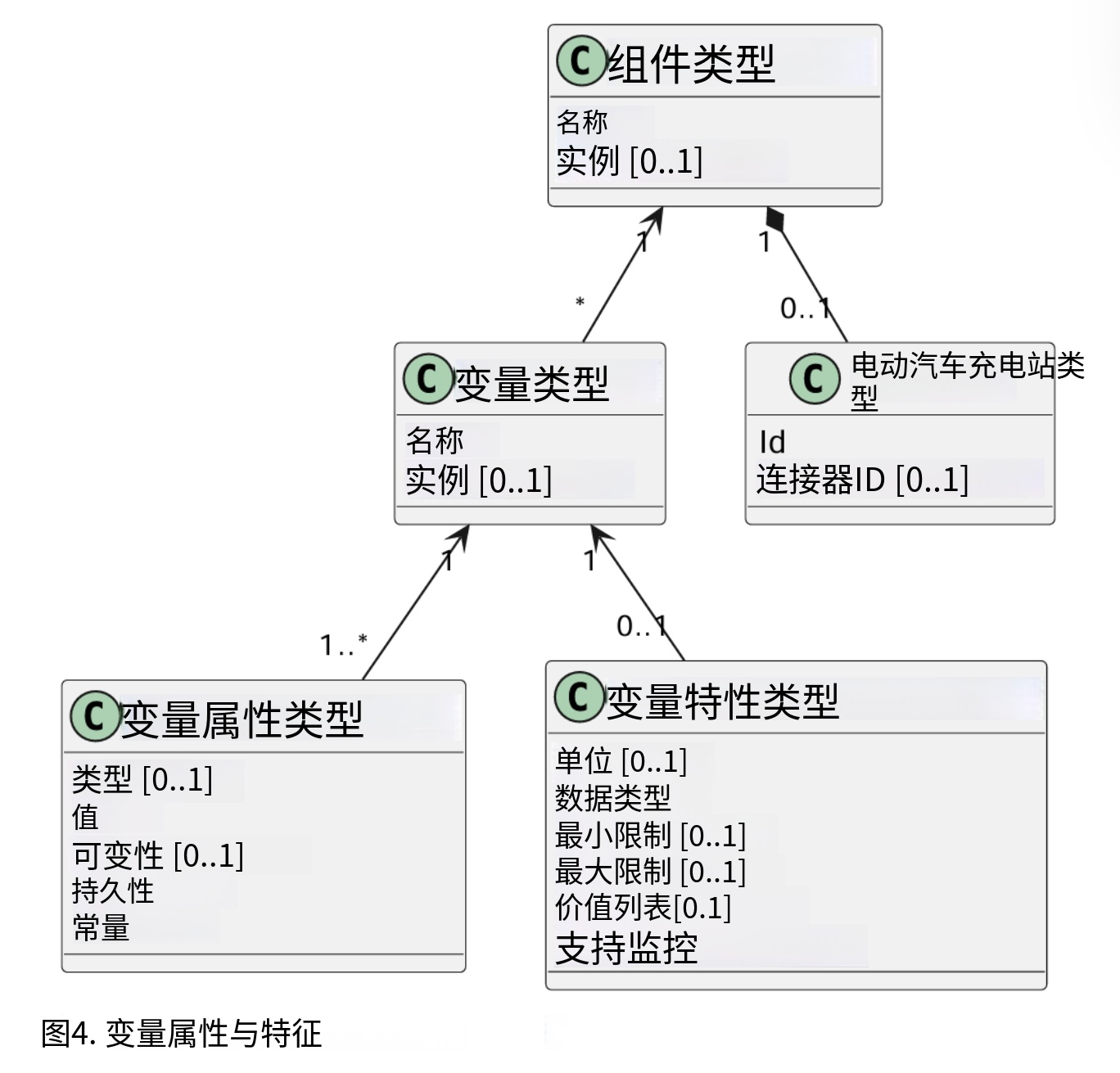
4.3. Characteristics and Attributes
Each variable, in addition to its primary ("Actual") value, can have a set of associated secondary data that is linked to the same primary variable name and variableInstance.
This greatly avoids cluttering the variables namespace with confusing clusters of ancillary variable names (e.g. FanSpeed, FanSpeedUnits, MinimumFanSpeed, BaseFanSpeed) that lack consistence and discoverability. The ancillary variable data includes:
• Variable characteristics meta-data (read-only)
◦ Unit of measure (V,W,kW,kWh, etc.)
◦ Data type (Integer, Decimal, String, Date, OptionList, etc.)
◦ Lower limit ◦ Upper limit
◦ List of allowed values for enumerated variables
译文
|---------|---------|--------|
| 无线通信链路 | 计量控制单元 | 枪头锁定装置 |
| 身份识别读取器 | 过流断路器 | 枪头锁定装置 |
| 主控控制器 | 剩余电流保护器 | |
| | 充电状态指示灯 | |
[基础家用充电桩配置示例]
|---------|----------|---------|
| 充电桩层级 | EVSE 层级 | 连接器层级 |
| 充电桩(整体) | EVSE(整体) | 连接器(整体) |
| 供电接入单元 | 供电接入单元 | 接入防护装置 |
| 身份识别读取器 | 身份识别读取器 | 枪头锁定装置 |
| 显示屏 | 显示屏 | |
| 税务级计量装置 | 税务级计量装置 | |
| 时钟模块 | 计量控制单元 | |
| 主控控制器 | 过流断路器 | |
| | 剩余电流保护器 | |
| | 充电状态指示灯 | |
[公共充电桩配置示例]
4.2 变量
每个组件均配备若干变量,可根据实际需求存储、配置、读取以及上报该组件所有对外公开数据,包含配置参数、电流温度等实测数值,以及变量数值的变动监控信息。
多数组件会配备自身专属变量(例如连接器组件的连接器类型变量),同时规范定义了一套基础标准化变量,用于统一实现全局或定向的高层事件通知、状态上报(如故障状态、运行状态),也可在设备盘点与发现流程中上报组件在位状态、可用状态等信息(如设备存在、设备启用)。
若设备存在、设备可用、设备启用这三类基础变量为只读且默认值为真,充电桩无需主动上报。当充电桩未上报上述变量时,中央管理系统将默认其为只读状态且取值为真。
变量可采用布尔型、整型、浮点型、日期时间型、字符串型等通用数据类型,同时也可限定变量取值范围、枚举选项及有序集合。
为适配复杂组件场景,同一组件下可创建多个同名变量实例(例如多路功率变换模块分别上报多点温度、电流、电压数据),不同变量实例通过可选的变量实例标识字符串唯一区分。变量支持无实例形态与多实例形态并存,未填写变量实例标识时,默认引用无实例变量。
4.3 特征与属性
每个变量除核心实际数值外,还可绑定一组附属衍生数据,且共用同一变量名与变量实例标识。
该设计可避免因增设各类附属变量(如风速、风速单位、最低风速、基准风速等)造成变量命名杂乱、标准不统一、设备发现困难等问题。变量附属数据包含:
- 变量特征元数据(只读)
- 计量单位(伏特、瓦、千瓦、千瓦时等)
- 数据类型(整型、浮点型、字符串、日期、选项列表等)
- 取值下限、取值上限
- 枚举类变量的合法取值列表
原版页码:8
原文
• Variable attributes (read-write):
◦ Actual value ◦ Target value
◦ Configured lower limit
◦ Configured upper limit
◦ Mutability (whether the value can be altered or not, e.g. ReadOnly or ReadWrite)
◦ Persistence (whether the value is preserved in case of a reboot or power loss)
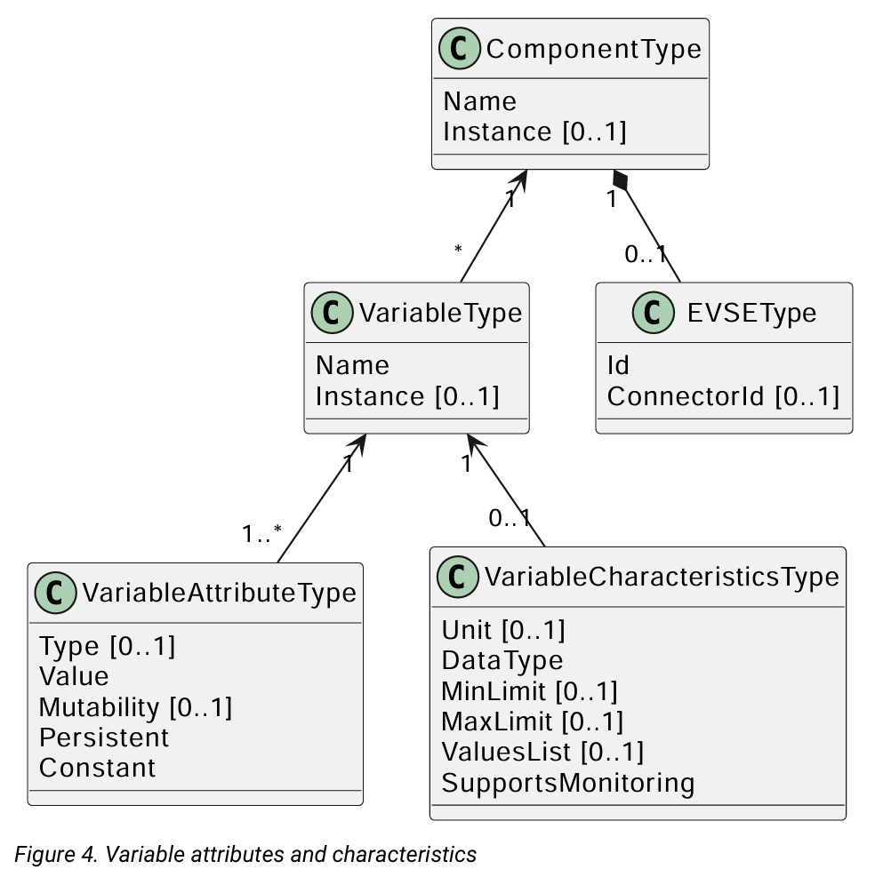
The relationship of a Variable with one or more VariableAttributes is illustrated in the figure below.
There is a difference between how to implement (physical) devices and (virtual) controller components, using the DeviceModel. A (virtual) controller component has to be implemented as described in part 2 chapter the "Referenced Components and Variables". These kind of components/variables are only using the variableAttribute type 'Actual'. Depending on if this variableAttribute is writable, the CSMS can use this to set a new value.
(Physical) devices are a bit more complex to implement. For example, there is a fan with a fan speed, that has a (physical) limit with a range of 0 - 1000. But it should not be allowed to set the value below 200, because the fan can stop functioning. And it should not be set above 500, because that would be bad for the fan on the long run. When implementing this device using the DeviceModel, it can be defined as follows:
译文
- 变量属性(可读写)
- 实际值
- 目标值
- 配置下限值
- 配置上限值
- 可修改性(数值是否允许更改,分为只读、读写)
- 持久化属性(设备重启或断电后数值是否保留)
变量与一项或多项变量属性的对应关系如下图所示。
采用设备模型实现物理设备与虚拟控制器组件的方式存在差异。虚拟控制器组件必须按照规范第 2 部分中引用组件与变量 章节所述要求进行开发,此类组件与变量仅使用实际值这一变量属性类型,该属性若支持写入,充电桩管理系统便可通过其下发新的设定值。
物理设备的实现逻辑则相对更为复杂。举例而言,某风扇转速物理量程为 0 至 1000,但实际使用中转速不得低于 200,否则风扇会停止运转;同时转速也不可高于 500,长期高转速会损伤设备。借助设备模型对该设备进行配置定义时,可采用如下方式设定:
原版页码:9
原文
|-------------|-------------------------|------------|--------------------------------------------------------------------------------------------------------------------------------------------------------------------------|
| Component | name | Fan | |
| Variable | name | FanSpeed | |
| Variable | variableAttribute 1 | type | Actual |
| Variable | variableAttribute 1 | value | <The current fan speed value of the fan.> |
| Variable | variableAttribute 1 | mutability | ReadOnly |
| Variable | variableAttribute 2 | type | Target |
| Variable | variableAttribute 2 | value | <The CSMS can use this value to adjust the fan speed. The Charging Station SHALL try to keep the actual value at the target value.> |
| Variable | variableAttribute 2 | mutability | ReadWrite |
| Variable | variableAttribute 3 | type | MaxSet |
| Variable | variableAttribute 3 | value | <The value '500' from the example. The target may not be set above this value.> |
| Variable | variableAttribute 4 | type | MinSet |
| Variable | variableAttribute 4 | value | <The value '200' from the example. The target may not be set below this value.> |
| Variable | variableCharacteristics | maxLimit | <The value '1000' from the example. This could be the physical max limit of the fan.> |
| Variable | variableCharacteristics | minLimit | <The value '0' from the example. This could be the physical min limit of the fan. This could also be -1000, if the fan is also able to rotate in the other direction.> |
| Description | This is an example of how a fan could be defined using the DeviceModel. |||
When trying to set the target with value 600, the Charging Station will first check the allowed min and max values/limits and reject the set. If the target value is set to 500, the value is within range and the Charging Station will allow the set and start to adjust the actual fan speed. If the actual fan speed is measured to be 502, it's out of range. But it should be reported to the CSMS, so the actual value of a physical component should be updated without checking the min and max values/limits.
4.4. Monitoring
Optional monitoring settings can be associated with a variable, that allow changes to variable (Actual) values are to be reported to the CSMS as event notifications. These include:
•Monitoring value
•Monitoring type: upper threshold, lower threshold, delta, periodic
•Severity level when reporting the event
The following table show which MonitorType/dataType combinations are possible.
|-----------------------|------------|-------------|-------------|--------------|-------------|----------------|------------------|----------------|
| | string | decimal | integer | dateTime | boolean | OptionList | SequenceList | MemberList |
| UpperThresh old | | × | × | | | | | |
| LowerThresh old | | × | × | | | | | |
| Delta | × | × | × | × | × | × | × | × |
| Periodic | × | × | × | | × | × | × | × |
| PeriodicCloc kAligned | × | × | × | | × | × | × | × |
•For UpperThreshold and LowerThreshold the value represents the to be exceeded value by the actual value of the variable.
•For Delta this value represents the change in value compared to the actual value from the moment the monitor was set.
◦When the dataType of the variable is integer or decimal, this value represents the absolute difference to be reached to trigger the monitor.
◦When the dataType of the variable is dateTime the unit of measure will be in seconds.
◦When the dataType of the variable is string, boolean, OptionList, SequenceList or MemberList, this value is ignored. The monitor will be triggered by every change in the actual value.
•When a delta monitor is triggered OR when the Charging Station has rebooted, the Charging Station shall set a new momentary value.
• For Periodic and PeriodicClockAligned the value represents the interval in seconds.
译文
|------|------|------|--------------------------------------------|
| 组件名称 | 风扇 | | |
| 变量名称 | 风扇转速 | | |
| 变量 | 属性 1 | 类型 | 实际值 |
| | 属性 1 | 说明 | 风扇当前转速数值 |
| | 属性 1 | 可修改性 | 只读 |
| | 属性2 | 类型 | 目标值 |
| | 属性2 | 说明 | 充电桩管理系统(CSMS)可通过该值调节风扇转速,充电桩需尽力将实际转速维持在目标值 |
| | 属性2 | 可修改性 | 可读可写 |
| | 属性 3 | 类型 | 设定最大值 |
| | 属性 3 | 数值 | 示例取值 500,目标值不得超出该上限 |
| | 属性4 | 类型 | 设定最小值 |
| | 属性4 | 数值 | 示例取值 200,目标值不得低于该下限 |
| | 变量特征 | 物理上限 | 示例取值 1000,为风扇物理转速最大值 |
| | 变量特征 | 物理下限 | 示例取值 0,为风扇物理转速最小值;若风扇支持反转,该值也可设为 - 1000 |
| 说明 | 以上为使用设备模型定义风扇设备的示例。 |||
若尝试将目标值设置为 600,充电桩会优先校验合法上下限范围并拒绝该配置;若目标值设为 500,处于合规区间内,充电桩将允许配置并开始调节实际风扇转速。 若实测实际转速为 502,即便超出设定区间也需如实上报至充电桩管理系统,即物理组件的实际值更新无需校验设定上下限。
4.4 监控
变量可配置可选监控参数,当变量实际值发生变动时,以事件通知形式上报至充电桩管理系统,相关配置包含:
- 监控阈值
- 监控类型:上限阈值、下限阈值、差值变化、周期上报
- 事件上报时的告警级别
下表列出所有支持的监控类型与数据类型组合方式。
|----------|-----------|-------------|------------|--------------|------------|----------------|------------------|----------------|
| | 字符串string | 十进制数decimal | 整数 integer | 日期时间dateTime | 布尔值boolean | 选项列表OptionList | 序列列表SequenceList | 成员列表MemberList |
| 上限阈值 | | X | X | | | | | |
| 下限阈值 | | X | X | | | | | |
| 差值变化 | X | X | X | X | X | X | X | X |
| 周期上报 | X | X | X | | X | X | X | X |
| 时钟对齐周期上报 | X | X | X | | X | X | X | X |
- 上限阈值、下限阈值:该数值为临界值,变量实际值超出此数值即触发监控。
- 差值触发:代表自监控配置生效起,变量数值的变动幅度。
- 整型、浮点型变量:达到设定绝对差值即触发监控;
- 日期时间型变量:单位为秒;
- 字符串、布尔值、选项列表、序列列表、成员列表类型:该设定值无效,变量实际值发生任意变更均直接触发监控。
- 差值监控触发或充电桩重启后,设备需重新记录当前瞬时基准值。
- 周期上报、时钟对齐周期上报:设定数值代表上报间隔,单位为秒。
原版页码:10
原文
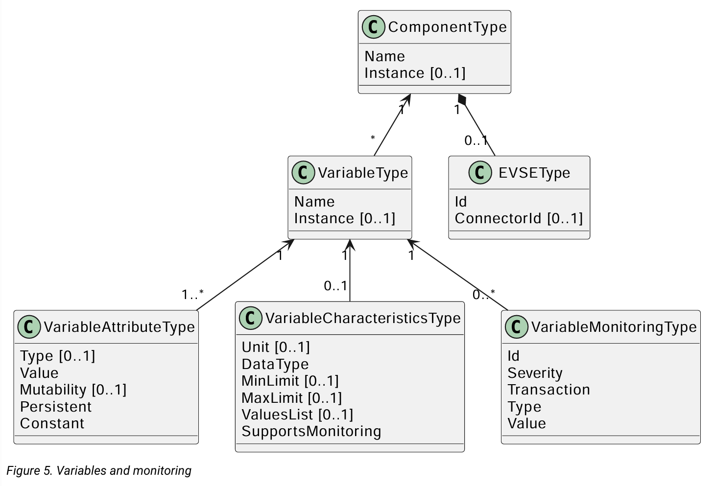
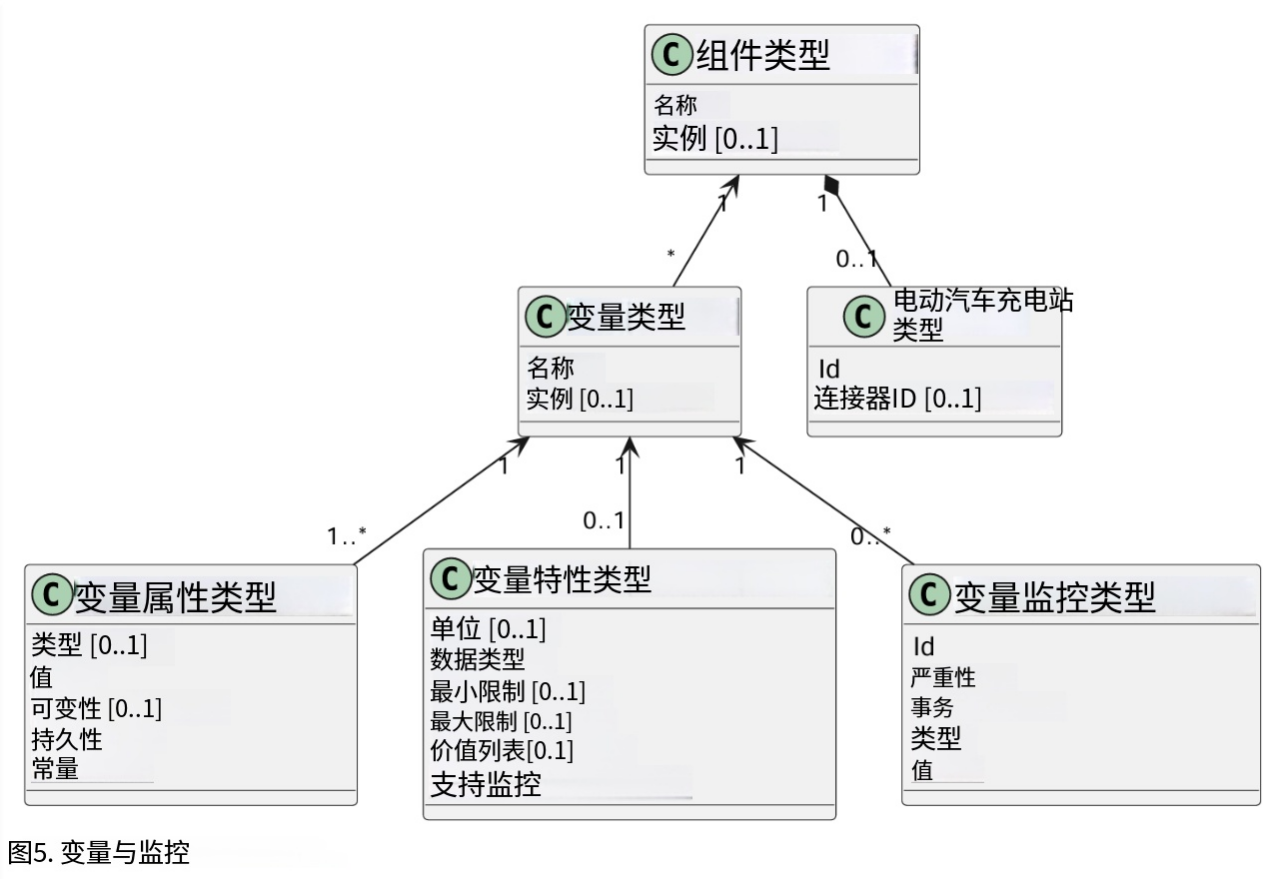
The relationship between a Variable and one or more VariableMonitoring elements is illustrated in the figure below.
4.5. Standardized lists of Components and Variables
To provide some level of interoperability between different Charging Stations and CSMSs, besides the above defined model of Components and Variables, part 2 - appendices of the OCPP specification provides a list of standardized names for Components and Variables. The idea of this lists is to make sure that if a Charging Station and CSMS want to exchange information about a component, they both use the same name and description if it is listed in the OCPP specification. For names of a Components or Variables that are not listed in the specification, bilateral appointments between Charging Station manufacturer and CSMS are to be made. In these cases it is advised to provide feedback to the Open Charge Alliance to be able to include new/additional Components and Variables in new versions of OCPP.
4.6. Minimum Device Model
Since the Device Model is a generalized mechanism which can be applied to any model of Charging Station, the complexity of different implementations can vary. It consists of a number of use cases and messages that are not all required. This section describes the minimum part of the Device Model that needs to be implemented to create a working implementation of OCPP 2.0.1.
The Device Model introduces Components and Variables that can be used for configuring and monitoring a Charging Station. A number of these Components and Variables are included in the list of Referenced Components and Variables (grouped by Functional Block) in Part 2 of the specification. When implementing a Functional Block, ALL required Configuration Variables that belong to a Functional Block SHALL be implemented. The required Configuration Variables from the General section SHALL also be implemented for all implementations of OCPP 2.0.1.
The following table describes which messages are required to implement for use cases that are part of the Device Model implementation.
译文
变量与一项或多项变量监控项的关联关系如下图所示。
4.5 组件与变量标准化清单
为实现不同充电桩与中央管理系统之间一定程度的互通性,除上述组件与变量模型外,OCPP 规范第 2 部分附录还提供了组件与变量的标准化命名清单。制定该清单的目的在于:若充电桩与管理系统需要交互某类组件相关信息,且该组件已录入规范清单,则双方必须统一使用规范内的名称与释义。
未录入规范的组件及变量名称,需由充电桩厂商与平台方自行协商定义。同时建议相关方将这类新增内容反馈至开放充电联盟,以便在后续 OCPP 版本中纳入官方标准。
4.6 最简设备模型
设备模型属于通用适配机制,可适配各类充电桩设备,不同设备的实现复杂度存在差异,其配套的用例与报文并非全部强制实现。本节明确搭建可用的 OCPP 2.0.1 环境时,设备模型必须实现的最低功能范围。
设备模型定义了可用于充电桩配置与状态监控的各类组件和变量,其中部分内容收录在规范第 2 部分按功能模块划分的引用组件与变量清单内。开发某一功能模块时,必须完整实现该模块下所有必填配置变量;所有 OCPP 2.0.1 设备,还需统一实现通用章节内的全部必填配置变量。
下表列明落地设备模型相关用例时,必须实现的通信报文。
原版页码:11
原文
|-----------------------------|--------------------------------------------------------------------------------------------------------------------------------------------------------------------------------------------------------------------------------------------------------------------------------------------|
| Use cases / messages that are part of a minimium Device Model implementation ||
| Use case | Messages |
| B05 Set Variables | SetVariables message MUST be implemented |
| B06 Get Variables | GetVariables message MUST be implemented. |
| Use cases / messages that are part of a minimium Device Model implementation ||
| B07 Get Base Report | GetBaseReport message MUST be implemented and MUST support ConfigurationInventory and FullInventory. The content of these reports depends on the implementation of the Charging Station. It is up to the implementer to decide which components and variables exist in the implementation. |
| Additional use cases / messages that are not part of a minimium Device Model implementation ||
| Use case | Messages |
| B08 Get Custom Report | GetCustomReport message is optional. |
| N02 Get Monitoring Report | GetMonitoringReportRequest message is optional. |
| N03 Set Monitoring Base | SetMonitoringBaseRequest message is optional. |
| N04 Set Variable Monitoring | SetVariableMonitoringRequest message is optional. |
| N05 Set Monitoring Level | SetMonitoringLevelRequest message is optional. |
| N06 Clear/Remove Monitoring | ClearVariableMonitoringRequest message is optional. |
| N07 Alert Event | it is RECOMMENDED that NotifyEventRequest is implemented in the Charging Station even when monitoring is not implemented, so that this can be used to report built-in monitoring events. |
| N08 Periodic Event | see N07. |
译文
|--------------|--------------------------------------------------------------------------------|
| 最简设备模型需实现的用例与报文 ||
| 用例 | 信息 |
| B05设置变量 | 必须实现设置变量报文 |
| B06获取变量 | 必须实现获取变量报文 |
| B07获取基础上报 | 必须实现 获取基础上报报文,且需支持配置清单 与全量清单两种上报类型;上报内容由充电桩实际业务实现决定,组件与变量均由开发方自主定义 |
| 非最简标配、可选实现的用例及报文 ||
| 用例 | 信息 |
| B08获取自定义上报 | 获取自定义上报报文为可选 |
| N02获取监控上报 | 获取监控上报请求报文为可选 |
| N03设置监控基准 | 设置监控基准请求报文为可选 |
| N04设置变量监控 | 设置变量监控请求报文为可选 |
| N05设置监控级别 | 设置监控级别请求报文为可选 |
| N06清除 / 移除监控 | 清除变量监控请求报文为可选 |
| N07告警事件 | 推荐充电桩实现事件通知请求报文,即便未部署自定义监控功能,也可依靠该报文上报设备内置监控告警事件 |
| N08周期事件 | 同 N07 建议 |
| | |
原版页码:12
原文
Chapter 5. Information Model vs. Device Model
As described above, the terms Information Model and Device Model refer to different concepts. The Information Model refers to a model of the information structure upon which the messages and datatypes in OCPP are based, whereas the Device Model refers to a generalized mechanism within OCPP to enable any model of Charging Station to report how it is build up so, it can be managed from any CSMS without defining the structure of the Charging Station in advance.
译文
第 5 章 信息模型与设备模型的区别
如上所述,信息模型 与设备模型是两个完全不同的概念。
信息模型 :是 OCPP 协议中报文、数据类型所依托的信息结构模型,作为协议报文与数据字段的设计基础。
设备模型:是 OCPP 内置的通用适配机制,支持各类充电桩自主上报自身硬件架构,无需提前预设充电桩设备结构,即可被任意充电桩管理平台统一管控。
原版页码:13
原文
Chapter 6. Using OCPP for other purposes than EV charging
As indicated in the introduction of this document, OCPP is primarily intended for two way communication between a CSMS and a Charging Station. However, with the addition of the Device Model as described in the chapter Device Model, OCPP can additionally be used for other purposes. For example, the reporting of Events or Status changes in transformers or stand-alone battery packs might also be useful for companies that are rolling out EV charging infrastructure. In this example, a BootNotification could be used to connect these devices to a management system. In the device model a device that is not a Charging Station, can be recognized by the fact that the component Charging Station is not present at the top level. At the moment the OCPP specification does not provide use cases for non Charging Station devices. However, they may be added in a future version of OCPP.
译文
第 6 章 OCPP 协议在电动汽车充电以外场景的应用
如本文开篇所述,OCPP 协议最初主要用于充电桩管理平台 与充电桩之间的双向通信。
而随着设备模型功能的完善,OCPP 还可拓展应用至其他业务场景。例如布局充电基础设施的企业,可借助该协议上报变压器、独立储能电池组等设备的事件信息与状态变更数据。
此类非充电设备可通过设备上线通知 报文接入管理平台;在设备模型中,顶层不存在充电桩组件,即可判定该设备并非充电终端。
目前 OCPP 规范暂未针对非充电类设备制定专属业务用例,相关功能或将在后续协议版本中补充完善。
原版页码:14
原文
Chapter 7. Numbering
This section is normative.
7.1. EVSE numbering
To enable the CSMS to address all the EVSEs of a Charging Station, EVSEs MUST always be numbered in the same way. EVSEs numbering (evseIds) MUST be as follows:
• The EVSEs MUST be sequentially numbered, starting from 1 at every Charging Station (no numbers may be skipped).
• evseIds MUST never be higher than the total number of EVSEs of a Charging Station
• For operations initiated by the CSMS, evseId 0 is reserved for addressing the entire Charging Station.
• For operations initiated by the Charging Station (when reporting), evseId 0 is reserved for the Charging Station main controller.
Example: A Charging Station with 3 EVSEs: All EVSEs MUST be numbered with the IDs: 1, 2 and 3. It is advisable to number the EVSEs of a Charging Station in a logical way: from left to right, top to bottom incrementing.
7.2. Connector numbering
To enable the CSMS to address all the Connectors of a Charging Station, Connectors MUST always be numbered in the same way. Connector numbering (connectorIds) MUST be as follows:
• The connectors are numbered (increasing) starting at connectorId 1 on every EVSE
• Every connector per EVSE has a unique number
• ID of the first Connector of an EVSE MUST be 1
• Additional Connectors of the same EVSE MUST be sequentially numbered (no numbers may be skipped)
• connectorIds MUST never be higher than the total number of connectors on that EVSE
Example: A Charging Station with 3 EVSEs that each have 2 connectors, is numbered as follows:
• EVSE 1 has connectors with connectorId 1 and 2
• EVSE 2 has connectors with connectorId 1 and 2
• EVSE 3 has connectors with connectorId 1 and 2
7.3. Transaction IDs
TransactionIds are now generated by the Charging Station and MUST be unique on this Charging Station for every started transaction.
In OCPP 1.x this was done by the CSMS.
The format of the transaction ID is left to implementation. This MAY for example be an incremental number or an UUID.
译文
第 7 章 编号规则
本章内容为正式强制性规范
7.1 EVSE 编号规则
为方便平台统一寻址充电桩内所有 EVSE,EVSE 编号必须统一遵循以下规则:
- 单台充电桩内 EVSE 从1 开始连续顺次编号,禁止跳号
- EVSE 编号不得超出该充电桩实际 EVSE 总数
- 平台下发操作指令时,0 号 EVSE代表整台充电桩整体
- 充电桩主动上报数据时,0 号 EVSE代表充电桩主控单元
示例:一台设备搭载 3 路 EVSE,编号固定为 1、2、3;建议按从左至右、从上至下的逻辑顺序编排。
7.2 连接器编号规则
连接器编号统一规范:
- 每一路 EVSE 下的连接器均从1开始递增编号
- 同一 EVSE 内连接器编号唯一
- EVSE 首个连接器编号必须为 1
- 同 EVSE 下多个连接器连续编排,禁止跳号
- 连接器编号不得超过该 EVSE 实际连接器总数
示例:3 个 EVSE,每个 EVSE 配备 2 个枪头
- EVSE1:连接器 1、2
- EVSE2:连接器 1、2
- EVSE3:连接器 1、2
7.3 交易流水号
OCPP 2.0.1 中交易 ID 由充电桩本地生成,同一设备内每笔充电交易 ID 必须唯一; OCPP1.x 版本则由平台生成。 交易 ID 格式无强制标准,可自定义实现,支持自增数字、UUID 等形式。
原版页码:15
原文
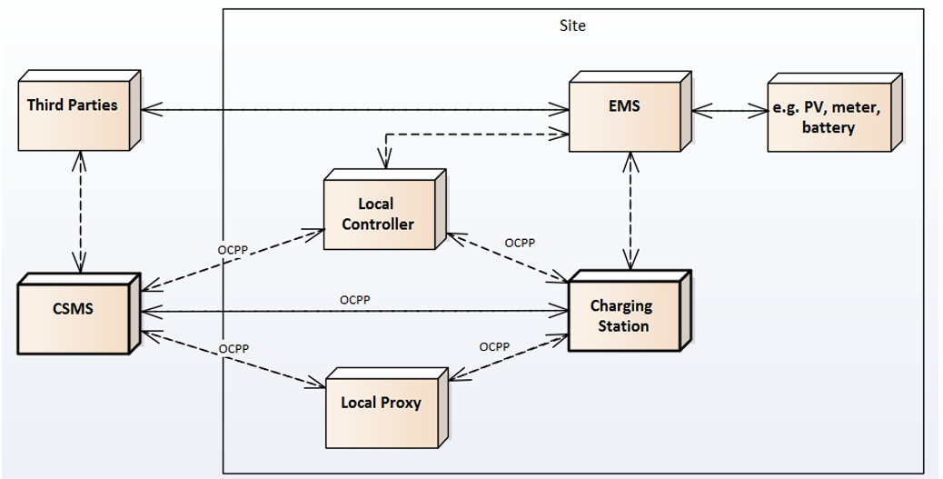
Chapter 8. Topologies supported by OCPP
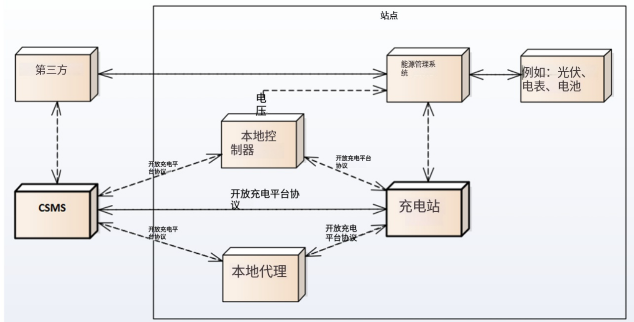
This chapter shows a number of topologies for using OCPP. As indicated in the introduction, OCPP was originally used for a setup where each Charging Station communicates directly with the CSMS. It is important to keep in mind that OCPP has no knowledge of the topology of the Charging Station network. The following figure shows the possible components in a setup using OCPP and the relations between these components:
8.1. Charging Station(s) directly connected to CSMS
Description
This is the basic setup for using OCPP.

8.2. Multiple Charging Stations connected to CSMS via Local Proxy
Description
In some situations it is desirable to route all communications for a group of Charging Stations through a single network node (i.e. modem, router, etc.). A typical example is the situation where a number of a Charging Stations are located in an underground parking garage with little or no access to the mobile network. In order to provide access to mobile data the Charging Stations are linked to a central data communications unit over a LAN. This central unit connects to the mobile network and acts as a proxy between CSMS and Charging Stations. Such a unit is called a "local proxy" (LP) in OCPP. A local proxy acts as a message router. Neither the CSMS nor the Charging Stations are aware of the topology of the network. For the Charging Stations in the group the local proxy "is" the CSMS. Similarly, for the CSMS the local proxy "is" the Charging Station. The diagram below illustrates this configuration.

译文
第 8 章 OCPP 支持的组网拓扑
本章介绍 OCPP 协议可适配的多种组网架构。 如前文所述,OCPP 最初应用场景为充电桩直连充电运营管理平台 。需明确:OCPP 协议本身不感知充电桩实际组网拓扑结构。
下图展示 OCPP 组网架构中包含的各类组成单元,以及各单元之间的交互关系。
8.1 充电桩直连充电管理平台
说明 这是 OCPP 协议最基础、最标准的部署组网架构。

8.2 多充电桩通过本地代理接入平台
说明 部分场景下,需将一组充电桩的所有通信数据统一经由同一个网络节点转发,如调制解调器、路由器等设备。
典型应用场景:地下车库等移动网络信号薄弱区域,充电桩先通过局域网接入统一数据通信单元,再由该单元接入公网,在平台与充电桩之间承担数据转发作用,OCPP 中将这类中转设备定义为本地代理(LP)。
本地代理仅负责报文路由转发,平台与充电桩均无法感知实际组网结构。 对旗下充电桩而言,本地代理等同于管理平台;对平台而言,本地代理等同于终端充电桩。具体组网架构见下方示意图。

原版页码:16
原文
8.3. Multiple Charging Stations connected to CSMS via Local Controller
Description
Whereas a local proxy does little more than route OCPP messages, a Local Controller can send messages to its Charging Stations,independently of the CSMS. A typical usage for this is the local smart charging case described in the Smart Charging chapter of Part 2 of OCPP, where a Local Controller can impose charge limits on its Charging Stations. In order for a Local Controller to be addressed by the CSMS, it needs to have its own Charging Station identity. From the point of view from OCPP, the Local Controller will just be a Charging Station (without any EVSEs/Connectors). The CSMS will possess the logic to deal with the Local Controller in order to support, for example, local smart charging. It is up to the implementation of the CSMS, whether the group topology is manually configured or deduced from the network based on IP addresses and information in BootNotifications. The diagram below illustrate this configuration.

NOTE:
Technically this topology can be realized in multiple ways. When using this setup with websockets, this implies that when a Charging Station connects to the Local Controller, it should open a websocket connection with the same address to the CSMS. The advantages of this approach is that the Local Controller can see all the messages and act on it, messages don't have to wait, firmware updates etc. on the Charging Stations are possible and the CSMS does not need special software. It could (in big installations) lead to a lot of websocket connections between CSMS and LC needed. For further information, please refer to OCPP implementation guide in Part 4.
8.4. Non-OCPP Charging Stations connected to CSMS via OCPP Local Controller
Description
This setup has multiple non-OCPP Charging Stations that are abstracted away using a OCPP enabled Local Controller. When applying OCPP in this situation, the LC should be considered as a Charging Station with many EVSEs or the LC should act as multiple OCPP Charging Stations (having their own Charging Station Identity).

8.5. DSO control signals to CSMS
Description
This is a set-up in which the CSMS is the only application sending signals to a its Charging Stations, but the CSMS receives smart charging signals from a DSO based on (most likely) grid constraints. This means that a non-OCPP signal such as OpenADR or OSCP is received and based on this signal, the CSMS limits charging on its Charging Stations. CSOs that want full control over their Charging Station use this architecture, this way they are in control of the amount of energy being used by their Charging Stations. This can be done by sending charging profiles / charging schedules to Charging Stations.

译文
8.3 多充电桩通过本地控制器接入平台
说明 本地代理仅负责转发 OCPP 报文,而本地控制器可脱离平台自主向下属充电桩下发指令。
典型应用为 OCPP 第二部分智能充电章节所述的本地智慧调度场景,本地控制器可直接对所辖充电桩下达充电功率限流指令。
本地控制器需拥有独立充电桩身份标识,才可被平台寻址访问。在 OCPP 协议视角中,它等同于一台无 EVSE 与充电接口的虚拟充电桩。
平台需配套对应业务逻辑,以此适配本地智能充电等功能。集群组网拓扑,可由平台人工配置,也可依托设备上线通知报文信息、IP 地址自动识别判定。组网结构详见示意图。

备注
从技术层面,该组网拓扑可通过多种方式实现。采用 WebSocket 通信架构时,充电桩连接本地控制器的同时,需以相同地址建立直连平台的 WebSocket 链路。
该方案优势:本地控制器可监听全部通信报文并自主处理、报文无转发延迟、支持充电桩固件升级运维,且平台无需额外定制开发; 弊端:大型场站场景下,平台与本地控制器之间会产生大量 WebSocket 长连接。 更多细节可查阅 OCPP 第四部分实施指南。
8.4 非 OCPP 协议充电桩通过 OCPP 本地控制器接入平台
说明 该架构下,多台不兼容 OCPP 协议的老旧充电桩,由支持 OCPP 协议的本地控制器统一做协议封装适配。 实际对接时有两种实现形式:
- 将本地控制器视作一台搭载多路 EVSE 的标准 OCPP 充电桩;
- 让本地控制器模拟出多个独立 OCPP 充电桩身份,各自拥有专属设备标识。
原版页码:17
原文
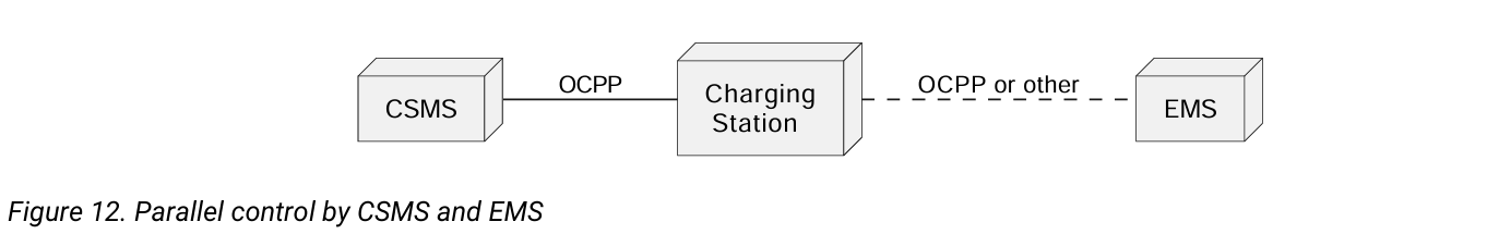
8.6. Parallel control by CSMS and EMS
Description
In a (semi-)private situation where a Charging Station is not only connected to the CSMS, but also to an Energy Management System, some form of parallel control should be supported. OCPP should at least be used for Charging Station maintenance, but OCPP 2.0.1 also supports reporting external smart charging control limits. So if the Energy Management System decides that charging at a later time is "better", the Energy Management System can impose an external limit (e.g. 0) to a Charging Station, which the Charging Station in turn can report to the CSMS via OCPP. The Energy Management System might get input from e.g. Local port of Smart Meter to prevent overloading connection but can also have other reasons for not charging (e.g. weather conditions).
译文
8.6 平台与能源管理系统并行管控
说明 半私有、私有场景中,充电桩同时对接充电管理平台与能源管理系统,需支持双重并行管控模式。
OCPP 协议至少承担充电桩运维相关交互工作,OCPP 2.0.1 还支持上报外部智能充电管控限值。 若能源管理系统判定延后充电更为合理,可向充电桩下发外部功率限制(如限值设为 0),充电桩再通过 OCPP 将该状态上报至充电管理平台。
能源管理系统可依托智能电表本地端口数据规避线路过载,也可依据天气等其他因素管控充电启停。
原版页码:18
原文
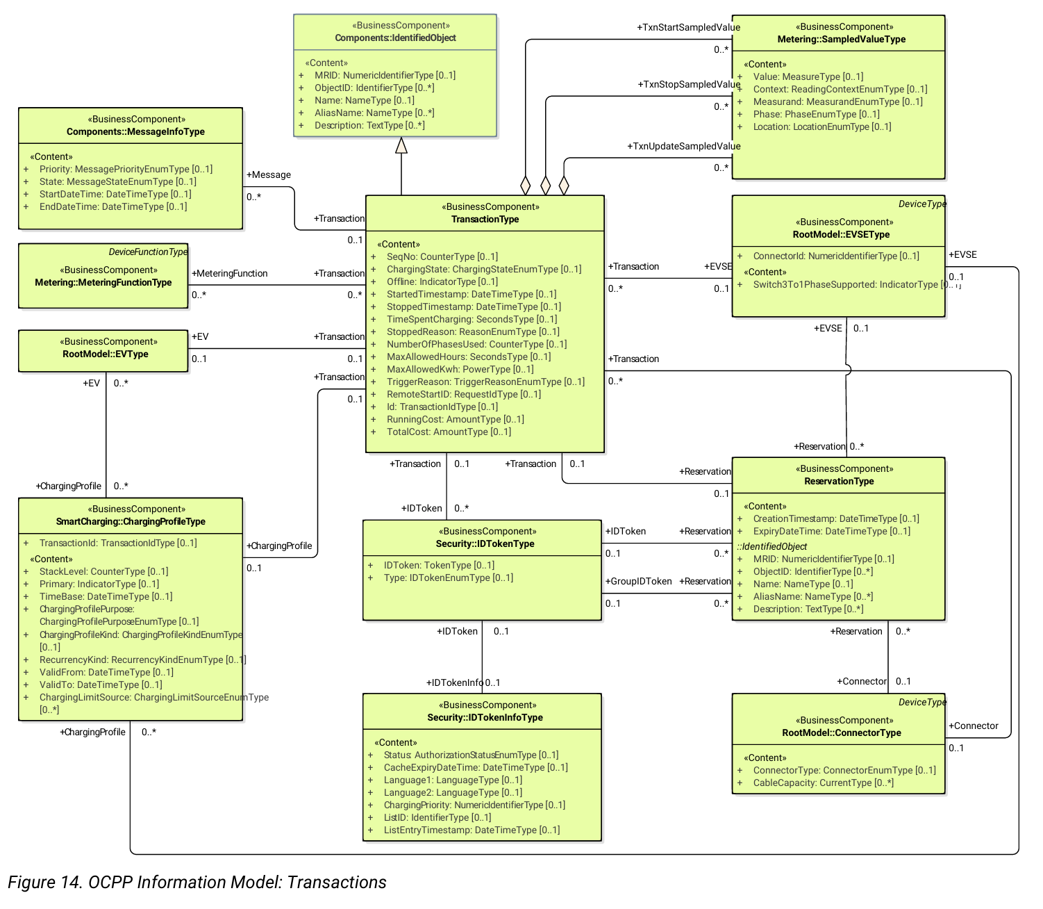
Chapter 9. Part 1 Appendix: OCPP Information Model
9.1. Explanation of UML representation and message generation
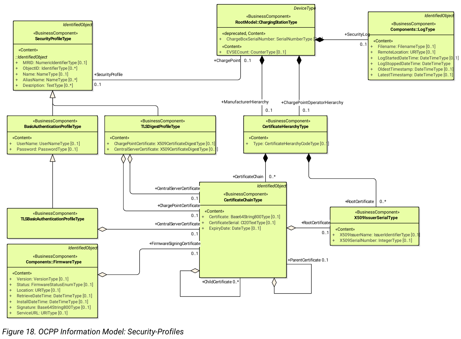
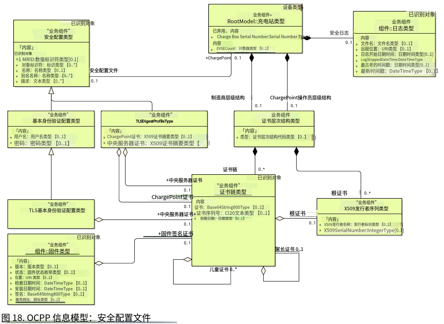
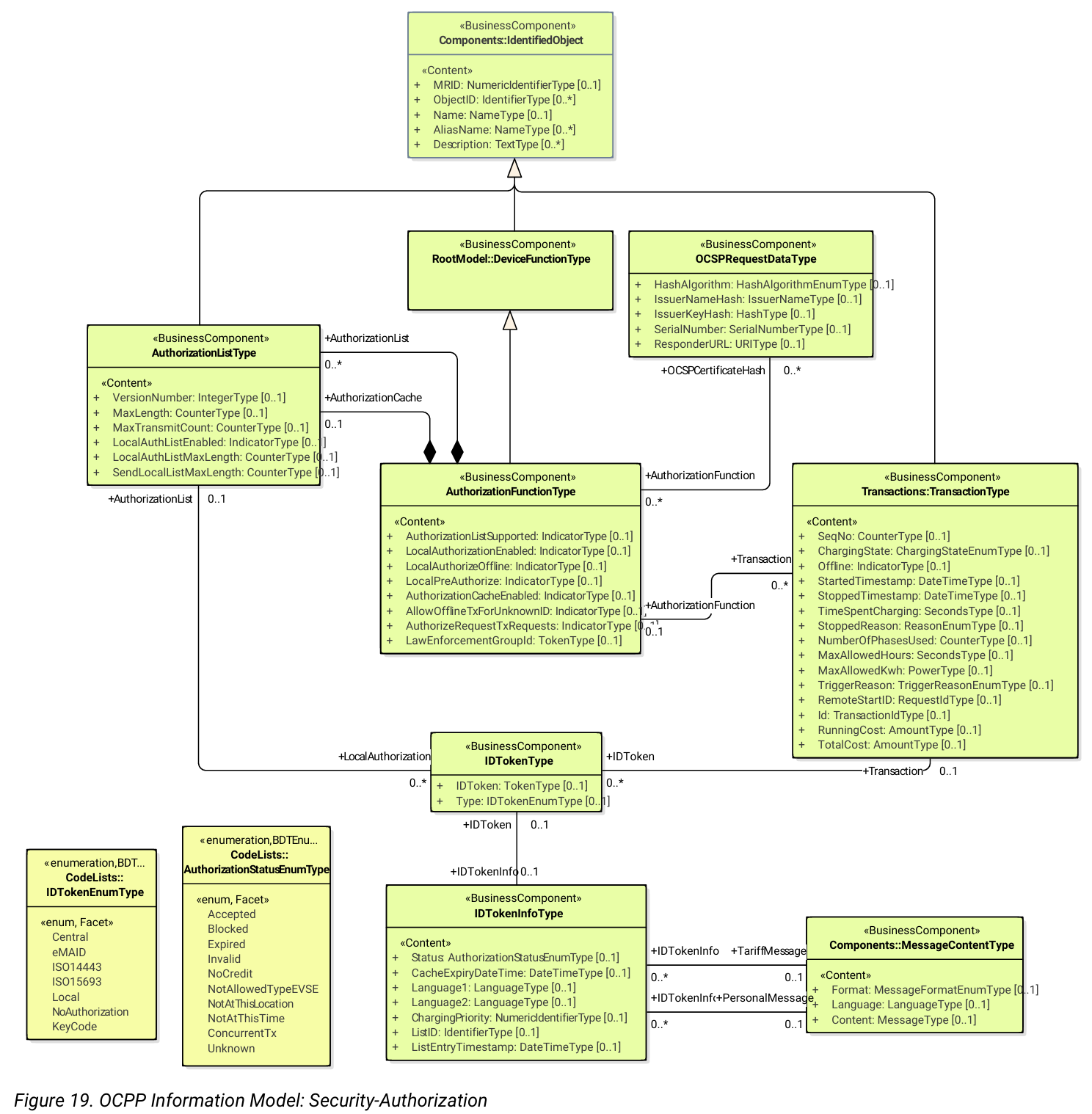
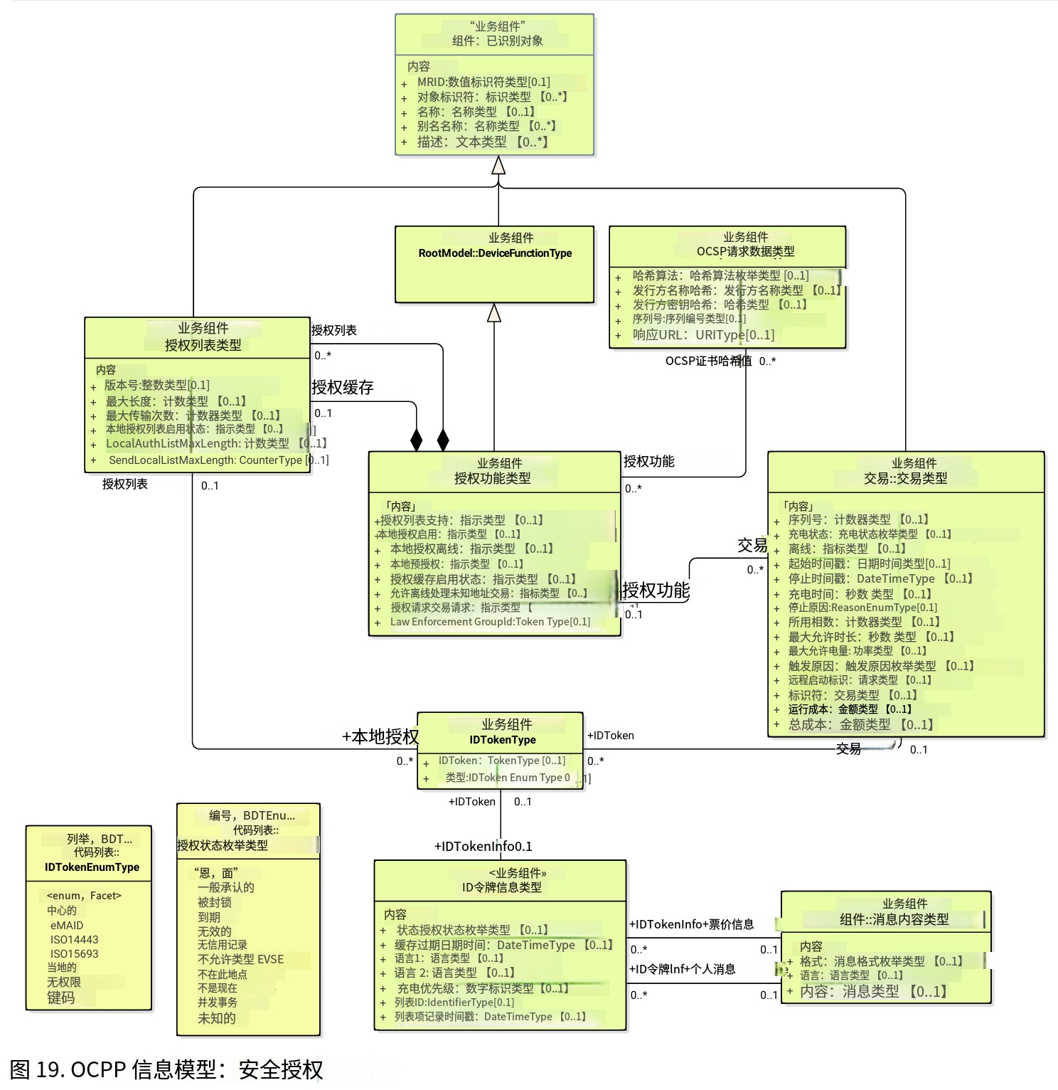
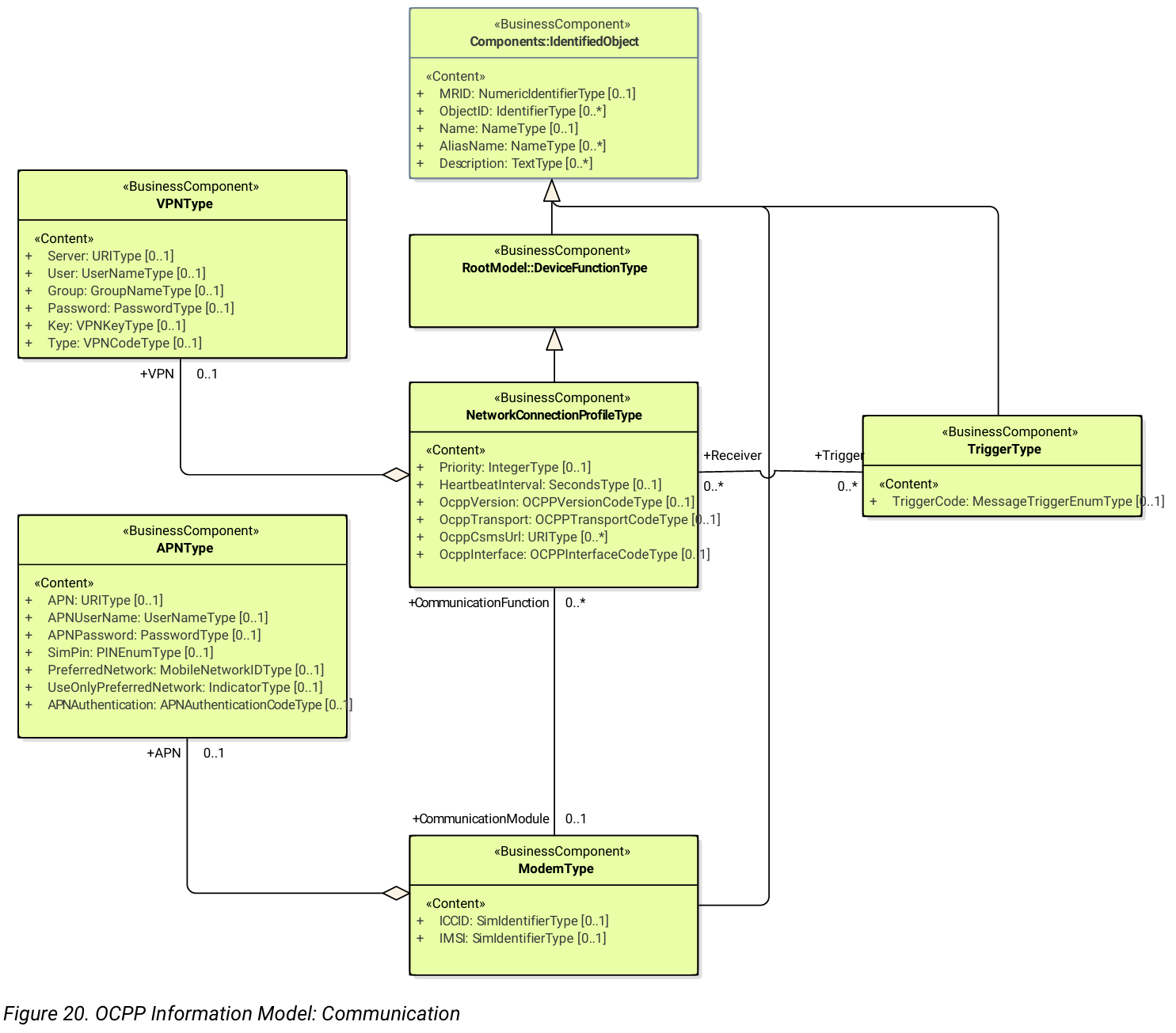
In the next paragraph, the UML schemes of the OCPP Information Model are shown. The model is based on the Common Information Model (CIM) and to some extent to the CEFACT naming standards (only part of the standard). The objects in the model are named BusinessComponents and inherit properties from the CIM IdentifiedObject, such as MRID and Name. In the UML diagrams the attributes that are inherited from IdentifiedObject are shown under the IdentifiedObject stereotype (between < < > >). Other attributes are listed under the stereotype < < Content > >. The messages in OCPP are derived from the model represented in the next paragraph, in a 3 step process:
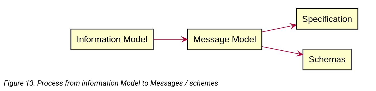
After creating the Information Model, the messages are created based on the Information Model. However, in this transition (first arrow), some rules are (manually) applied for modelling messages. The most important rule that is applied, is that messages containing a reference to a with only one , are replaced by a field with the name . For example, if a message contains a Transaction, with only an Id, this is replaced by a transactionId. In the next step, when generating the messages and datatypes section of Part 2 of the specification, for readability, all Core DataTypes such as CounterType, are replaced by the Primitive DataType they refer to (except for enumerations) in this example integer.
译文
第 9 章 第一部分附录:OCPP 信息模型
9.1 UML 图示说明与报文生成规则
下文将展示 OCPP 信息模型的 UML 结构图。该模型基于公共信息模型 CIM 构建,同时部分参考 CEFACT 命名规范。
模型中的对象统称为业务组件,继承 CIM 标识对象的属性,如资源标识、名称等。 UML 图里,标识对象派生属性归类于<<IdentifiedObject>>构造型下,其余属性归入<<Content>>构造型。
OCPP 协议报文依据该模型分三步生成。
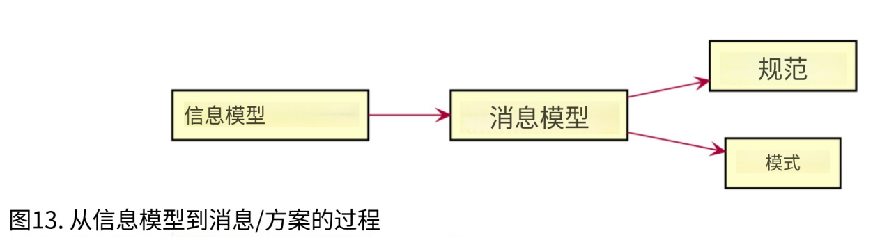
构建信息模型后,以此为基础生成协议报文。首次转换过程会遵循既定建模规则,核心规则为:若报文仅引用对象唯一标识字段,则直接替换为对应 ID 字段名。 例:报文内仅含交易标识的交易对象,统一替换为交易编号字段。
后续编制规范第二部分报文与数据类型章节时,为提升可读性,计数器类型等核心数据类型,除枚举类型外,均替换为其对应的基础原生数据类型,示例中对应整型。
原版页码:19
原文
9.2. Visual Representation of OCPP Information Model
译文
原版页码:20
原文
译文
原版页码:21
原文
译文
原版页码:22
原文
译文
原版页码:23
原文
译文
原版页码:24
原文
译文
原版页码:25
原文
译文
原版页码:26
原文
译文