前言
- 最近在进行项目调试的时候再次遇到了相机标定的问题,我们曾经在
ROS1中探讨过相机标定的原理和流程: - 本期主要分享一下相机标定的棋盘格生成、以及
ROS2中相机标定的一些注意事项与变化。
1 棋盘格生成
1-1 思路
-
一般来说,相机的标定需要借助标准的标定板。标定板越大,标定相对来说越准确。
-
但是标定板越大,价格就越贵,之前用的这块
30mm的标定板价格大致在¥400左右(虽然被打碎了)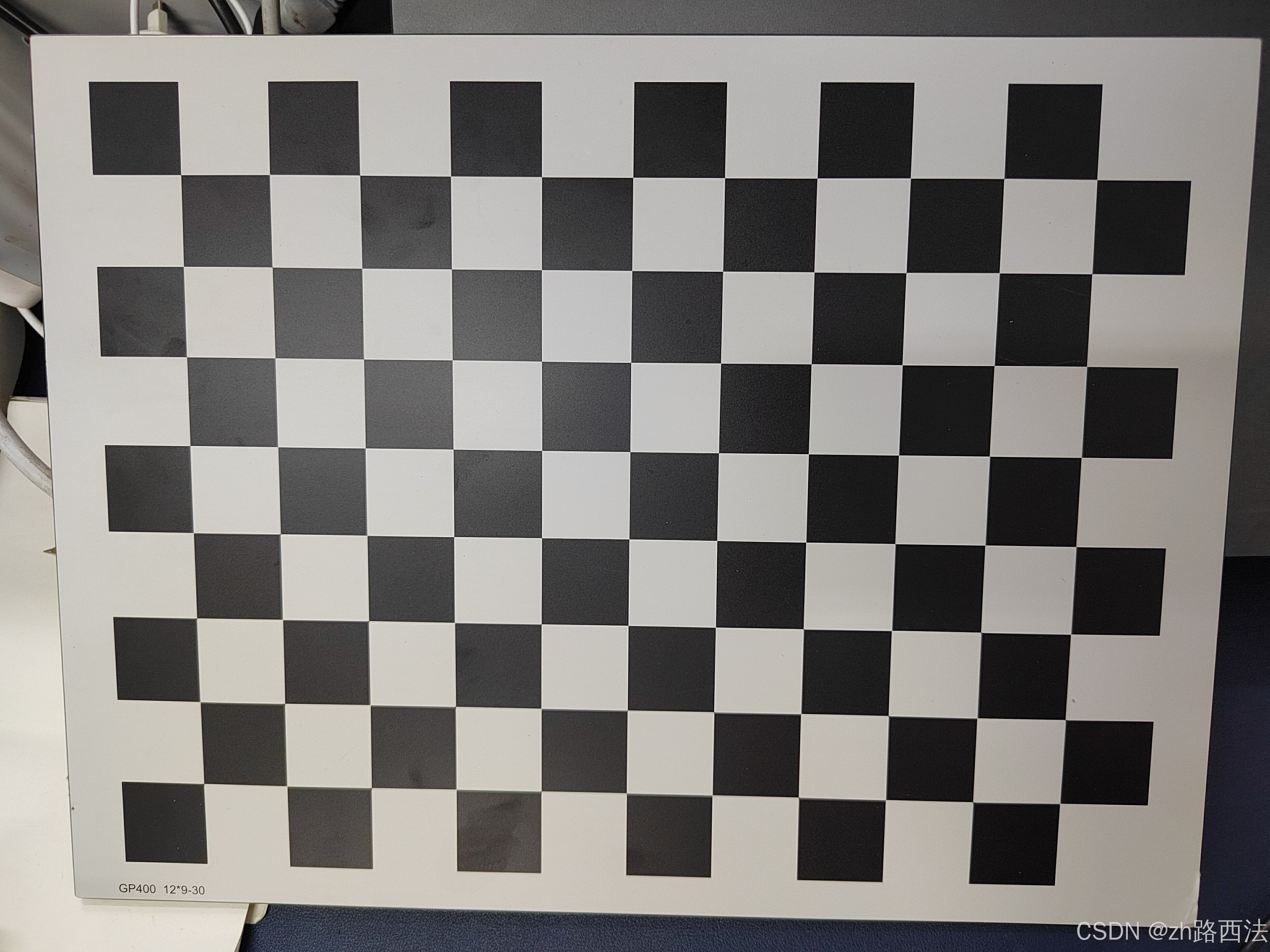
-
那么考虑到价格和性价比以及学习时候的临时使用,我们可以自己打印标定板。
1-2 自制打印棋盘格
- 借助
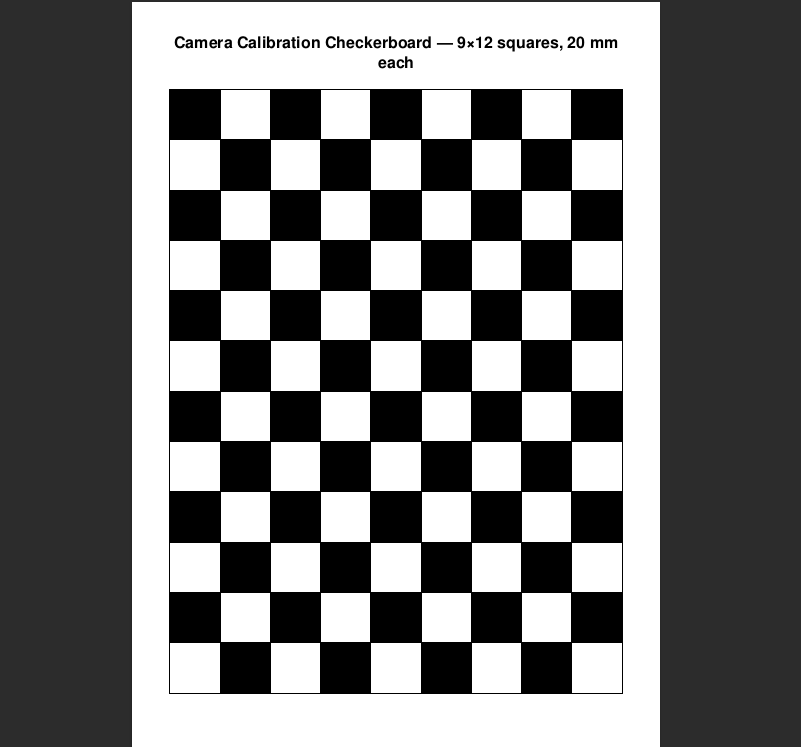
ReportLab(一个 Python 生成 PDF 的库 ),我们可以直接生成一个用于标定的20mm的棋盘格pdf文件
python
from reportlab.platypus import SimpleDocTemplate, Table, TableStyle, Spacer, Paragraph
from reportlab.lib import colors
from reportlab.lib.pagesizes import A4, landscape
from reportlab.lib.styles import getSampleStyleSheet
from reportlab.lib.units import mm

# Fix orientation per user: swapped width/height.
# Generate 9 columns x 12 rows, each 20 mm.
cols = 9
rows = 12
square = 20 * mm

filename = "chessboard_12rows_9cols_20mm.pdf"
styles = getSampleStyleSheet()

data = [["" for _ in range(cols)] for _ in range(rows)]
style_cmds = [("GRID", (0, 0), (-1, -1), 0.5, colors.black)]

for r in range(rows):
    for c in range(cols):
        fill = colors.black if (r + c) % 2 == 0 else colors.white
        style_cmds.append(("BACKGROUND", (c, r), (c, r), fill))

table = Table(
    data,
    colWidths=[square] * cols,
    rowHeights=[square] * rows,
)
table.setStyle(TableStyle(style_cmds))

doc = SimpleDocTemplate(
    filename,
    pagesize=A4,
    rightMargin=10 * mm,
    leftMargin=10 * mm,
    topMargin=10 * mm,
    bottomMargin=10 * mm,
)

story = [
    Paragraph("Camera Calibration Checkerboard --- 9×12 squares, 20 mm each", styles["Title"]),
    Spacer(1, 5 * mm),
    table,
]

doc.build(story)

print(f"Created {filename}")-
生成的效果大致如下:
-
经过测试,实际去打印店打出来的误差差不多在1mm左右,可以接受。
2 ROS2 相机标定
2-1 安装
- 和
ros1的安装一样,我们直接通过apt安装
bash
sudo apt install ros-$ROS_DISTRO-camera-calibration2-2 前置准备
- 注意:
cameracalibrator节点需要接受sensor_msgs/Image格式的图像文件 - 如果有些相机驱动发布的是
sensor_msgs/CompressedImage,你需要进行一次转发,这里可以使用ros2自带的工具进行转发:
bash
ros2 run image_transport republish compressed raw \
  --ros-args \
  -r in/compressed:=/camera/image_raw/compressed \
-r out:=/camera/image_rawin/compressed:=/camera/image_raw/compressed:原始压缩输入out:=/camera/image_raw:转换后话题输出
- 这里也提供一个cpp用 OpenCV 读取摄像头,并发布
sensor_msgs/msg/Image话题(通过cv_bridge转换)。 - 确保你安装了一下依赖
bash
sudo apt install ros-${ROS_DISTRO}-cv-bridge ros-${ROS_DISTRO}-image-transport
sudo apt install libopencv-dev- 新建cpp
cpp
#include <rclcpp/rclcpp.hpp>
#include <sensor_msgs/msg/image.hpp>

#include <cv_bridge/cv_bridge.h>
#include <opencv2/opencv.hpp>

class CameraPublisher : public rclcpp::Node
{
public:
    CameraPublisher() : Node("camera_publisher")
    {
        pub_ = this->create_publisher<sensor_msgs::msg::Image>(
            "/camera/image_raw", 10);

        cap_.open(0,cv::CAP_V4L2);  // 默认摄像头 /dev/video0

        if (!cap_.isOpened()) {
            RCLCPP_ERROR(this->get_logger(), "Failed to open camera!");
            rclcpp::shutdown();
            return;
        }

        timer_ = this->create_wall_timer(
            std::chrono::milliseconds(33),  // ~30 FPS
            std::bind(&CameraPublisher::timerCallback, this));
        std::cout<<"CameraPublisher Started!"<<std::endl;
    }

private:
    void timerCallback()
    {
        cv::Mat frame;
        cap_ >> frame;

        if (frame.empty()) {
            RCLCPP_WARN(this->get_logger(), "Empty frame!");
            return;
        }

        auto msg = cv_bridge::CvImage(
            std_msgs::msg::Header(),
            "bgr8",
            frame
        ).toImageMsg();

        msg->header.stamp = this->now();

        pub_->publish(*msg);
    }

    rclcpp::Publisher<sensor_msgs::msg::Image>::SharedPtr pub_;
    rclcpp::TimerBase::SharedPtr timer_;
    cv::VideoCapture cap_;
};

int main(int argc, char **argv)
{
    rclcpp::init(argc, argv);
    rclcpp::spin(std::make_shared<CameraPublisher>());
    rclcpp::shutdown();
    return 0;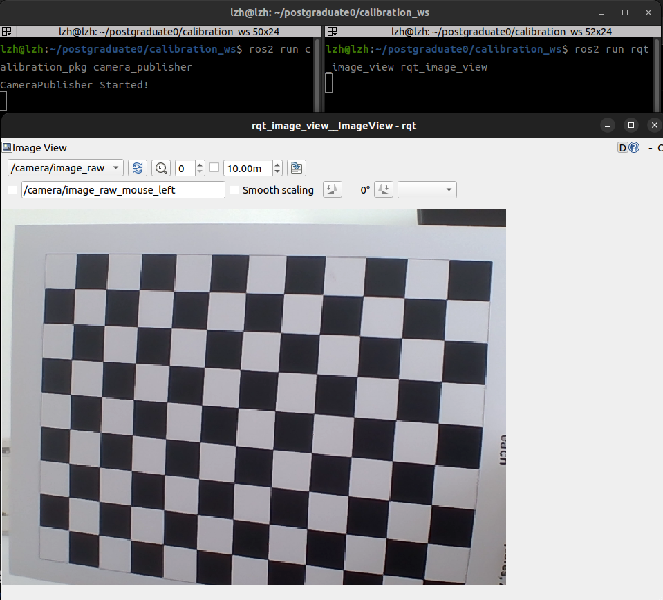
}- 运行后我们可以借助rqt进行可视化
bash
ros2 run rqt_image_view rqt_image_view- 效果如下
2-3 使用
bash
ros2 run camera_calibration cameracalibrator \
 --size 8x11 \
 --square 0.02 \
 --no-service-check \
--ros-args --remap image:=/camera/image_raw-
其中的参数:
-
size 8x11为内部的角点数量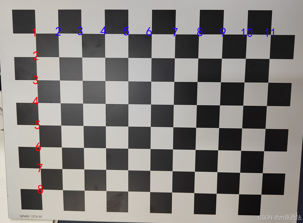
-
square 0.02为指定正方体的长度,单位是m -
no-service-check:禁用 service 可用性检查 -
--ros-args --remap image:=/camera/image_raw设置图像输入,格式一定要是sensor_msgs::msg::Image
-
-
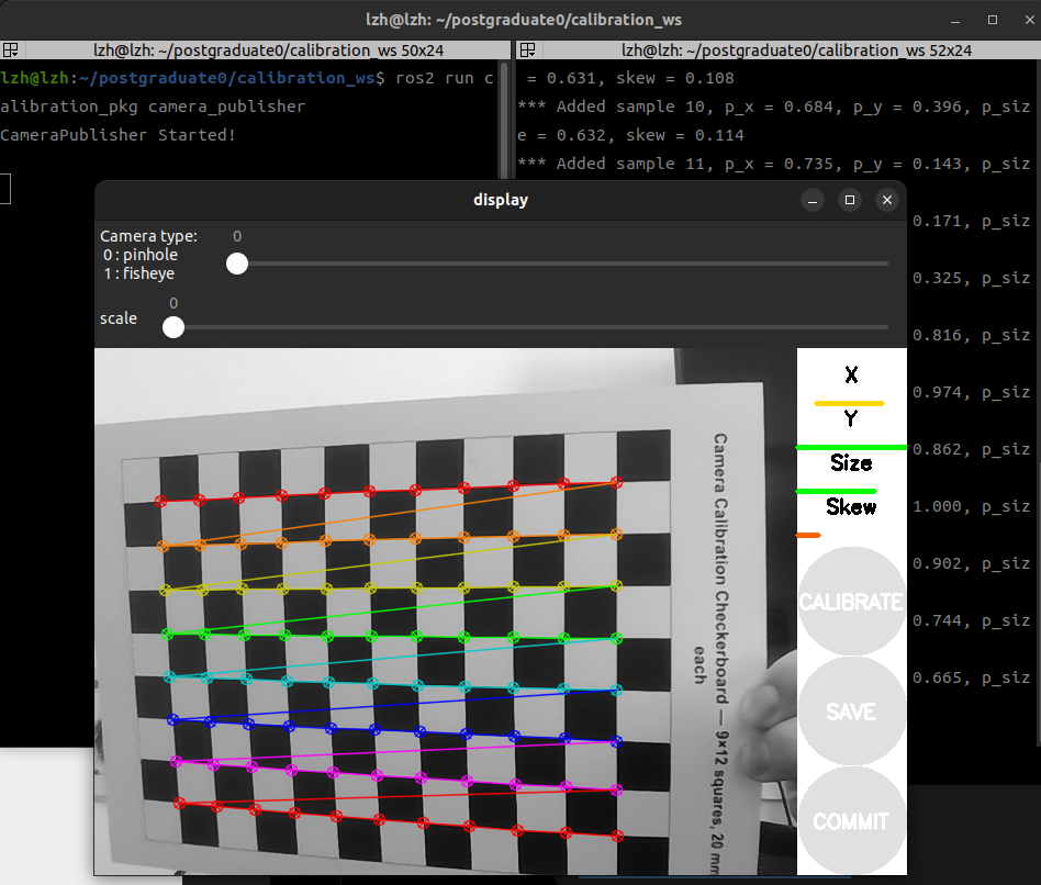
运行有:
-
基础参数:
Camera type摄像头类型:,这里我们选择00 pinhole针孔1 fisheye鱼眼
scale:比例,设置为1即可
-
根据右侧进度条提示进行移动棋盘格:
X: 棋盘格在摄像头视野中的左右移动
Y:棋盘格在摄像头视野中的上下移动Size:棋盘格在摄像头视野中的前后移动Skew:棋盘格在摄像头视野中的倾斜转动
-
我们需要不断移动棋盘格,不断采集四个进度条的数据,尽量让四个条都变成绿色
-
晃的差不多以后,
CALIBRATE按钮会变色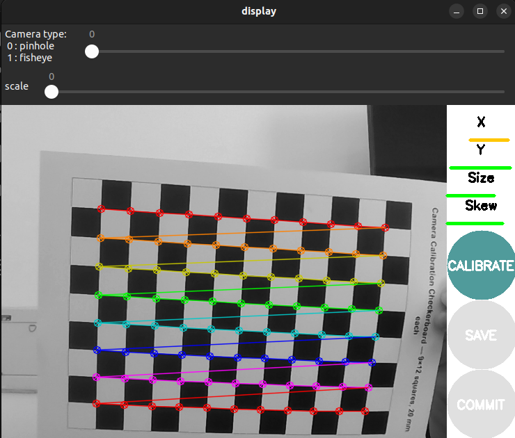
-
点击
SAVE,可以看到命令行输出: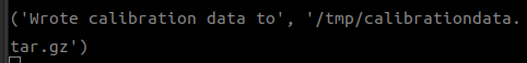
-
解压后就有标定文件了
yaml
image_width: 640
image_height: 480
camera_name: narrow_stereo

camera_matrix:
  rows: 3
  cols: 3
  data: [589.30405, 0.0, 329.54919,
         0.0, 586.3807, 249.68556,
         0.0, 0.0, 1.0]

distortion_model: plumb_bob
distortion_coefficients:
  rows: 1
  cols: 5
  data: [-0.037621, -0.167530, -0.007268, 0.000397, 0.0]

rectification_matrix:
  rows: 3
  cols: 3
  data: [1.0, 0.0, 0.0,
         0.0, 1.0, 0.0,
         0.0, 0.0, 1.0]

projection_matrix:
  rows: 3
  cols: 4
  data: [589.30405, 0.0, 329.54919, 0.0,
         0.0, 586.3807, 249.68556, 0.0,
         0.0, 0.0, 1.0, 0.0]
2-4 标定参数
- 注意正常情况下单目相机标定的结果会是:
yaml
image_width: 640
image_height: 480

camera_name: camera

camera_matrix:
  rows: 3
  cols: 3
  data: [fx,  0.0, cx,
         0.0, fy,  cy,
         0.0, 0.0, 1.0]

distortion_model: plumb_bob

distortion_coefficients:
  rows: 1
  cols: 5
  data: [k1, k2, p1, p2, k3]

rectification_matrix:
  rows: 3
  cols: 3
  data: [1.0, 0.0, 0.0,
         0.0, 1.0, 0.0,
         0.0, 0.0, 1.0]

projection_matrix:
  rows: 3
  cols: 4
  data: [fx,  0.0, cx,  0.0,
         0.0, fy,  cy,  0.0,
         0.0, 0.0, 1.0,  0.0]
2-4-1 camera_matrix(内参 K)
-
含义:把"相机坐标系里的3D点"投影成"像素坐标"
K = f x 0 c x 0 f y c y 0 0 1 K = \begin{bmatrix} f_x & 0 & c_x \\ 0 & f_y & c_y \\ 0 & 0 & 1 \end{bmatrix} K= fx000fy0cxcy1 -
其中:
- f x fx fx / f y fy fy:焦距(像素), 越大 → 视角越窄(像望远镜)
- c x cx cx / c y cy cy:主点(图像中心偏移),感光元件的偏移
-
本质:
- 把"归一化相机坐标"变成"像素坐标"
2-4-2 distortion_coefficients(畸变)
- 含义:修正"镜头不是完美针孔"的问题
- 总共有两种畸变:
- 径向畸变(k1, k2, k3):镜头边缘光学弯曲,有桶形,枕形
- 切向畸变(p1, p2):镜头和传感器没有完全平行,左右不对称
-
k 1 , k 2 , p 1 , p 2 , k 3 \] \[k_1, k_2, p_1, p_2, k_3\] \[k1,k2,p1,p2,k3
2-4-3 rectification_matrix(R)
-
含义:把相机坐标"旋正"
P = f x 0 c x 0 0 f y c y 0 0 0 1 0 P = \begin{bmatrix} f_x & 0 & c_x & 0 \\ 0 & f_y & c_y & 0 \\ 0 & 0 & 1 & 0 \end{bmatrix} P= fx000fy0cxcy1000
-
对于单目永远是单位矩阵
- 单目没有 stereo(没有左右相机对齐)
- 不需要旋转到统一视角
2-4-4 projection_matrix(P)
-
含义: "用于最终投影到图像的矩阵(给 SLAM / stereo 用)"
P = f x 0 c x 0 0 f y c y 0 0 0 1 0 P = \begin{bmatrix} f_x & 0 & c_x & 0 \\ 0 & f_y & c_y & 0 \\ 0 & 0 & 1 & 0 \end{bmatrix} P= fx000fy0cxcy1000 -
和 K 的区别:
K用于原始相机模型P用于校正后投影模型
-
最后一列表示单目没有 baseline(没有左右偏移)
[0, 0, 0]
2-5 全流程
bash
3D点 (X, Y, Z)
      ↓
相机坐标系
      ↓
归一化投影
      ↓
K(焦距+主点)
      ↓
畸变修正
      ↓
rectification(旋正)
      ↓
P(最终输出像素)
      ↓
2D图像点 (u, v)
总结
- 本文提到了相机标定的棋盘格生成、以及
ROS2中如何对单目相机进行标定。 - 如有错误,欢迎指出!
- 感谢观看!