ver0.1
前言
前文我们介绍了PSCI机制的灵魂:电源状态的协调机制。我们将整个PSCI机制分成两个部分PSCI-Proxy、PSCI-Server。PSCI-Proxy更贴近OSPM,而PSCI更贴近SCP是整个PSCI机制实现的核心部分。随着应用场景的变化,SOC复杂度和规模也在不断发展,当然这里面最核心的部分肯定是CPU,这也就是促成了PSCI的机制也在不断迭代升级。低版本的电源状态管理的实现集中在EL3的固件中,而高板的PSCI的实现有了进一步的细分,也就是将PSCI-Server从单一固件进一步细化成PSCI实现的策略层和传输层。这样就可以把PSCI机制的策略层从芯片厂商的PSCI的固件中剥离并上移到EL2甚至是EL1中,跟下游厂商提供了更加灵活的电源状态管理配置的可能性。上面说的就是Platform-coordinated mode和OS-initiated mode两种模式,如果不熟悉可以看一下我们前序的文章或者直接看手册。尘归尘、土归土,虽然我们行文中将PSCI看作一种机制,但实际上它还是ARM抽象出来的一层用于标准化ARM-PE-Cores电源状态的接口(Interface)。因此还是决定花费一篇文章的篇幅对PSCI做一下接口层面的介绍,也把接口在使用中的一些细节再梳理一下。同样在阅读本文之前,希望大家读一读我们的前序文章,掌握一些基础,也顺便找找感觉:
(4)A-25ARMv8/v9-GIC的系统架构(中断的硬件基础)
(5)A-38ARMv8/v9-Generic Timer系统架构
(6)A-41ARMv9/v8-电源管理系统架构(Power Management System Architecture)
(7)A-42ARMv9/v8-电源管理工作原理(SCP Service Overview)
(8)A-43ARMv9/v8-电源控制框架简介PCF(Power Control Framework Overview)
(9)A-0x2cARMv9/v8-电源管理域(Voltage Domain/Power Domain)
(10)A-45ARMv9/v8-电源模式(Power Modes)
(11)A-46ARMv9/v8-电源状态(Power States)
(12)V-05 虚拟化基础-异常模型(Exception)(AArch64)
(13)A-47ARMv9/v8-电源状态管理软件架构(PSCI架构)
(14)A-48ARMv9/v8-电源状态管理机制(PSCI协调机制)
正文
1.1 PSCI接口规范
既然是将PSCI的的接口,首先就让我们来认识一下它们,如图1-1所示:
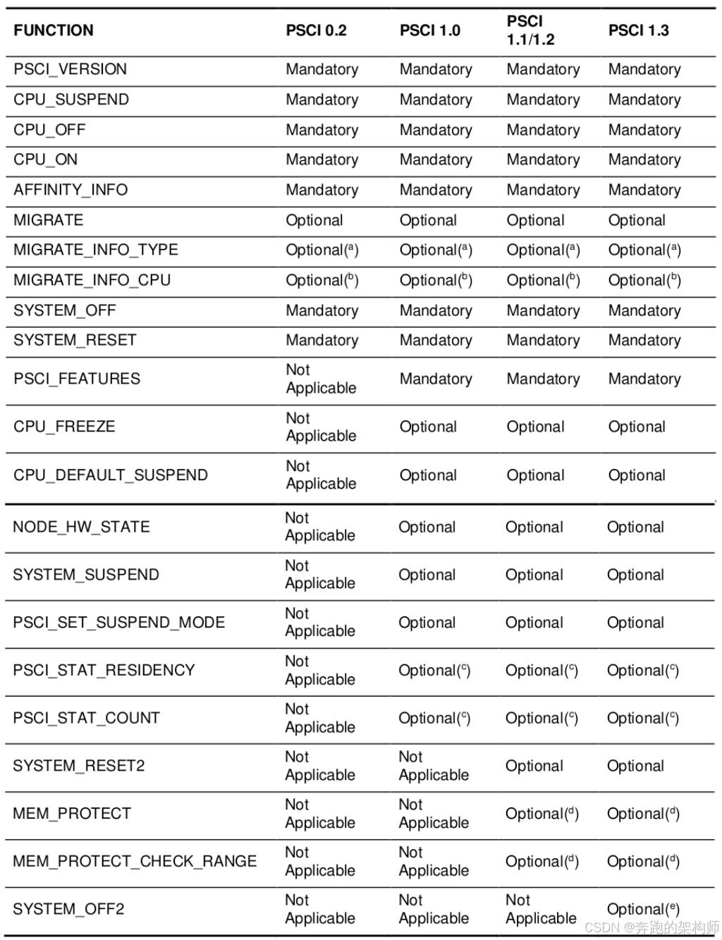
图1-1 Mandatory and optional functions for a given version of PSCI
我们看一下手册的描述:
The APIs are described here without reference to the underlying conduit (SMC or HVC). However, the functions adhere to the SMC Calling Conventions. In an implementation that includes EL2 but not EL3, a hypervisor providing support to a PSCI-compliant EL1 Rich OS can use HVC as the conduit. In the HVC case, the format of the call, in terms of immediate value, and register usage, is the same as in the SMC case. PSCI functions can only be called from the Normal or Realm Security states (EL1 or EL2).
结合图1-1,我们对PSCI的接口层面做一下简要的梳理:
(1) 首先是ARM规定好了PSCI接口涵盖的范围。除了直接对PE-Core的电源状态直接进行干预的接口之外,还覆盖了对系统(System)层的操作,还有PSCI接口的一些工具类的接口等。ARM对PSCI的机制肯定是做了整体的思考,但是对于这些接口的实现还是做了区分,一些是强制的(Mandatory),其余的则是可选(Optional)的。最后PSCI的接口也是在不断的迭代升级中,这个升级的过程也包含着接口数量的增加。
(2) 在ARM的异常模型的架构下,ARM希望PSCI的这些接口的调用者应该是EL1和EL2,实现方自然应该更靠近权限等级更高的EL3。Caller和Callee通过ARM的指令(HVC,SMC)进行传导,如图1-2所示。
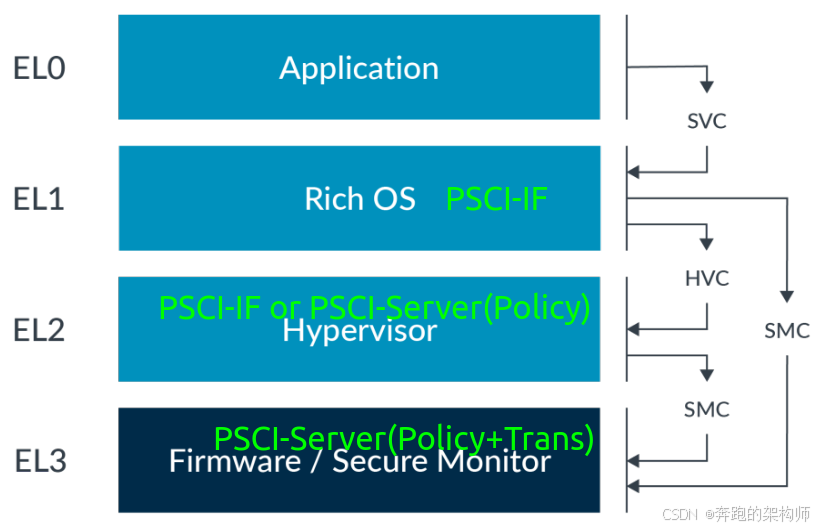
图1-2 Service call routing (PSCI)
详细的PSCI机制的架构,我们前面的文章中已经有过详细的讨论,大家可以翻翻前面的文章。另外,异常模型是我们进行ARM架构下各个子系统研究的基础,希望大家能花一些时间进行系统的学习。这里面我们贴出对PSCI用到的会同步异常指令的简要介绍,不展开讨论了:
The Arm architecture includes the exception-generating instructions SVC , HVC , and SMC . The purpose of these instructions is solely to generate an exception and enable the PE to move between Exception levels:
• The Supervisor Call ( SVC ) instruction enables a user program at EL0 to request an OS service at EL1
• The Hypervisor Call ( HVC ) instruction, available if the Virtualization Extensions are implemented, enables the OS to request hypervisor services at EL2
• The Secure Monitor Call ( SMC ) instruction, available if the Security Extensions are implemented, enables the Normal world to request Secure world services from firmware at EL3.
When the PE is executing at EL0, it cannot call directly to a hypervisor at EL2 or secure monitor at EL3, as this is only possible from EL1 and higher. The application at EL0 must use an SVC call to the kernel, and have the kernel perform the action to call into higher Exception levels.
Assuming the respective Exception levels have been implemented, the OS kernel (EL1) can execute an HVC instruction to call the hypervisor at EL2 or call the secure monitor at EL3 with the SMC instruction. Similarly, from EL2 the PE can use the SMC instruction to call the EL3 secure monitor.
(3) SMC调用的过程分成两部分一部分是传递参数,另外一部分就是完成调用。以Linux为例,图1-1中的PSCI接口会被定义为不同的Function ID,如图1-3所示:
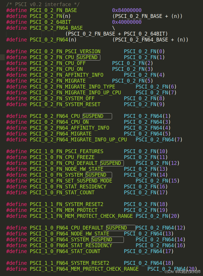
图1-3 PSCI Function ID(Linux)
需要注意的是,这些PSCI_FN_ID需要和DTS中PSCI的节点对应上,PSCI-Proxy端使用HVC还是SMC进行跳转也要对应上,如图1-4所示:
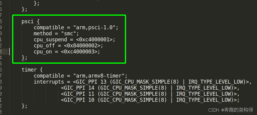
图1-4 PSCI Function ID(DTS)
确定了跳转指令(SMC or HVC),和Function ID之后,就可以给这个ID传递相应的参数完成跳转了,如图1-5的SMC的跳转方式,图1-6的HVC的跳转方式。SMC和HVC指令各个字段的详细介绍就不展开了,感兴趣的小伙伴可以自行阅读ARM的ISA手册。

图1-5 ISA-SMC

图1-6 ISA-HVC
1.2 PSCI接口详解
PSCI的接口列表和接口的调用方式我们已经大概搞清楚了,本小节我们将挑选一个PSCI规范中强制要求实现的接口进行介绍进而剖析PSCI各个接口的内部世界。
1.2.1 接口的原型
这里我们选接口CPU_SUSPEND加以描述:
The CPU_SUSPEND API is used to move a topology node into a low-power state. The function is called from a specific core in that topology node, and indicates that the caller intends to make use of the core in the future, but that it has no current work for it. The CPU_SUSPEND API is called by an OSPM as part of idle management.
CPU_SUSPEND接口的作用就是将(PE-Core 、 Cluster 、System)运行时的状态切换为暂停态,接口他具体形式如图1-7所示:
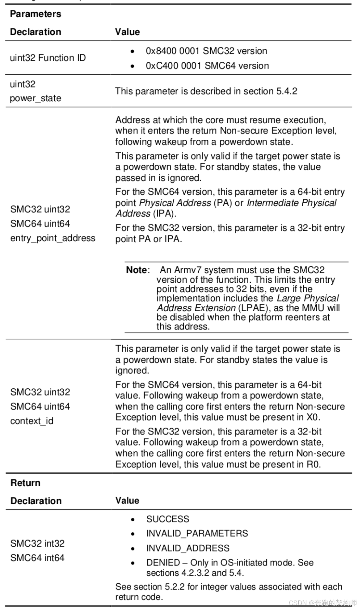
图1-7 CPU_SUSPEND Format
Function ID我们已经很熟悉了,我们将在本节重点介绍一下CPU_SUSPEND其他的参数和返回值。这里我们强调一下选择suspend接口的一个重要的原因,就是整个电源管理的流程中suspend是最容易产生死机黑屏问题的上下文,搞电源的小伙伴们一定要提高警惕。
1.2.2 电源状态(power_state)
先看一下参数power_state的原型,如图1-8所示:
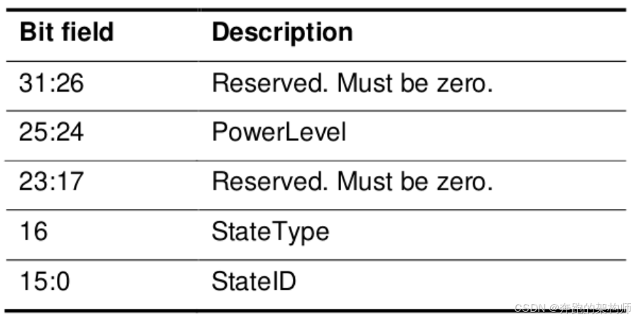
图1-8 power_state parameter bit fields in Original format
通过上图,可以看出power_state的有效字段为三个:PowerLevel、StateType、StateID。
PowerLevel
看一下手册的描述:
This field describes the power level, as defined in Chart 1-9, to be powered down, such as core, cluster, or group of clusters. Note that it is only possible to call CPU_SUSPEND from the current core, that is, it is not possible to request suspension of another core.
How the power levels are numbered is IMPLEMENTATION DEFINED, however, as described in Chart 1-9, it is expected that lower numbers are closer to the core and higher numbers are closer to the system. For the example system depicted in Figure 4, a logical numbering scheme is:
• Level 0: for cores
• Level 1: for clusters
• Level 2: for system
这里面我们直接贴一张图(图1-9)帮助大家理解,关于电源域的依赖关系就不展开了,前面的文章已经反复讨论过。
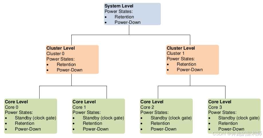
图1-9 Example power domain topology
结合图1-9,相信大家理解PowerLevel应该比较容易,这里我们还是强调两点:
(1) OSPM的维护者要搞清楚目前的CPU相关的系统架构,还要搞清楚目前PSCI-Server的实现。如果引入了虚拟化架构的SOC,对于Hypervisor的实现也是一种挑战,特别是对vCPU线程和pCPU有强绑定关系的情况。
(2) Suspend接口只能对调用的PE-Core所在的分支起作用,不能去主动的替别的PE-Core操心,但是不代表不会被别人干扰。具体还要看申请Suspend的上下文以及PSCI-Proxy的实现,如图1-10所示:
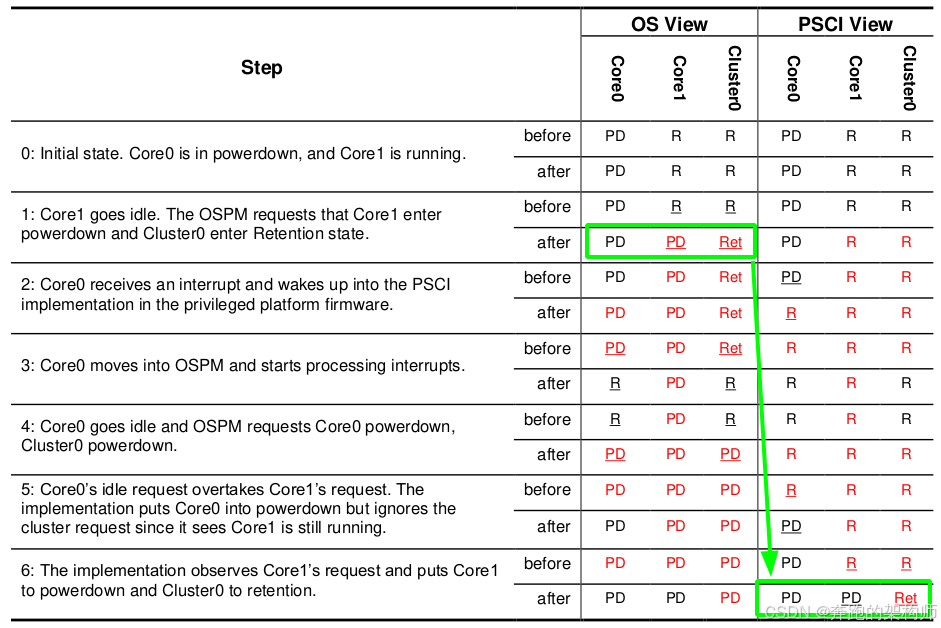
图1-10 Example race
看一下手册中的描述:
With OS-initiated coordination, the ordering of requests from different cores is critically important. If the implementation does not process requests in the order the calling OS intended, then it can put the implementation into the wrong state.
The race described above arises because the order in which the OSPM issues requests is not the order observed by the implementation. In rare cases, this might happen for a variety of potential reasons, for example, different frequencies on different cores, or different cache behavior. This sequence of events results in the implementation incorrectly acting on the stale Cluster0 request from Core1 rather than the
latest request from Core0. The net result is that Cluster0 is left in the wrong state until the next wakeup.
这个例子是一个想讲解在OS-initiated coordination mode下,如果PSCI-Server不进行临界状态管理,可能会打破last Core调用决定电源状态的原则。这里我们引用是想示范一下,在suspend接口调用的过程中,在PSIC-Server做出协调决策之前,有各种的干扰因素存在,请大家仔细体会。
StateType
申请状态类型:
A value of 0 indicates a standby or retention state as defined in Chart 1-9.
A value of 1 indicates a powerdown state as defined in Chart 1-9. This also indicates that entry_point_address and context_id fields contain valid data.
The state type is always considered to be powerdown if any core context is lost, even if, at power levels higher than a core, there is no loss of context. For example, if the state implies powering down a core but keeping a cluster in retention, the StateType field would denote powerdown.
这部分大家可以结合图1-9,应该很容易理解,其实就是搞懂电源状态的概念,以及电源域的拓扑结构下,各个Level节点所能够覆盖的电源状态的范围。
StateID
这个字段我们在前序文章中已经讲过了,就不展开讨论了。大家需要注意的是,PSCI-IF申请的电源状态是一组状态,而PSCI-Server决策出来的状态也是一组状态。
Field to express a platform-specific state ID. Contents are IMPLEMENTATION DEFINED.
This field can be used to distinguish which combination of local states is being requested.
Using StateID and the other fields in the power_state parameter, it must be possible to uniquely describe every composite power state that the calling OS can use. In addition, in OS-initiated mode, the StateID encoding must allow expressing the power level in which the calling core is the last to go idle. The method by which this is done must be expressed to the OSPM through firmware tables (FDT or ACPI), so that it can add this information to the StateID when requesting a power state.
1.2.3 entry_point_address
既然是Suspend了,那么总有Resume的时候,那么恢复的时候从哪儿执行总得告诉PE-Core一个地址,到那里去取指令开始执行吧:
The entry_point_address parameter is used by the caller to specify where code execution needs to resume at wakeup time. The parameter must be a Physical Address (PA), or, for a guest OS in a virtualized platform, an Intermediate Physical Address (IPA). In this case, the hypervisor must trap the call.
主要如果是虚拟化架构下,IPA这里要稍微注意下,如图1-11所示:
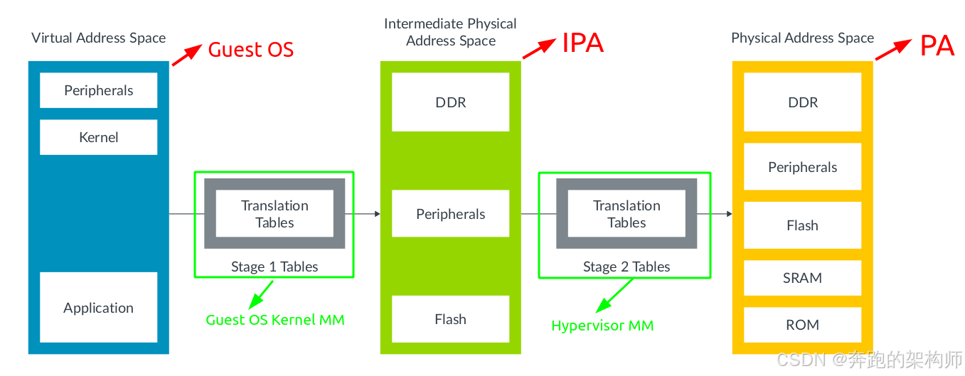
图1-11 Stage 2 IPAs to physical addresses
虚拟化架构下,Hypervisor会将系统内部的各种硬件资源虚拟化后重新调配,内存资源也不例外。Hypervisor隔离Guest OS和物理内存的手段就是通过两级地址翻译的机制,这也就催生了IPA。这样Guest OS的kernel中内存管理模块物理看到的物理地址视角其实是IPA,管理的也是IPA,对IPA的分配和释放都会陷入到Hypervisor的内存管理模块重新记账进行处理和真正的物理地址空间中的PA进行关联。这部分涉及到虚拟化技术的基本原理以及ARM体系下的内存管理方面的基础知识,我们在前面的文章中都有阐述,感兴趣的小伙伴,希望大家花一些时间研究一下,肯定会帮助大家更加深刻的理解PSCI的机制。
1.2.4 Context_id
上下文的ID:
The context_id parameter is only meaningful to the caller. The PSCI implementation must preserve a copy of the value passed in this parameter. Following wakeup from a powerdown state, the PSCI implementation must place this value in R0, W0, or X0, when it enters the first Non-secure Exception level. The context identifier can be used by the caller to point to the saved context that must be restored on a core when it starts up at the return Exception level. The caller can use other methods to implement this functionality.
Use of powerdown states in idle management, where context is lost, requires the ability to resume execution on a previously powered-down core. The return to execution must be transparent to the applications that were executing on the core before its shutdown. To achieve this, supervisory software must save the context of execution for the core. When a core resumes, its context must be restored so
that execution can restart from the same point with the same context. The execution context comprises architectural and non-architectural context. The context can also be categorized based on its visibility to the implemented Security states.
To enable preservation of context, every OS or supervisory software, running at each impacted Exception level, must provide a software stack that can:
• Save the architectural context that is otherwise lost when power is removed.
• Save the non-architectural state that is otherwise lost when power is removed. There might be SoC implementation-specific components that have a state that needs to be saved.
• Perform basic initialization and restoration of non-architectural and architectural context when power is reapplied.
在电源状态切换的过程中,为了让应用能够做到无感(事实上要100%做到很难),涉及到系统层面对Context的保存和恢复操作,参考图1-12所示:
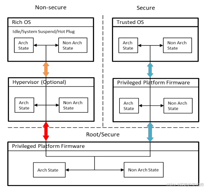
图1-12 Save and restoring context across operating systems
这部分也不展开讨论了,总之就是非常复杂(确实有门槛,建议大家读一下前面的文章),比如需要保存的系统架构层面的状态:
A non-exhaustive list of architectural state to consider preserving is provided below:
• The general-purpose register bank.
• The SVE, NEON and floating-point register bank.
• System control registers, for example, MMU and Generic Timer System control registers.
• Debug context.
• Trace context.
涉及到一个GIC子系统的处理也很复杂:
The following list provides an example of the save and restore operations that are required for GIC management:
• During a CPU_SUSPEND:
o Save and restore CPU interface registers, for example, binary point, priority mask, and control registers, if the CPU interface power domain is being powered down.
• During a CPU_OFF:
o Save and restore CPU interface registers, for example, binary point, priority mask, and control registers, if the CPU interface power domain is being powered down.
o Ensure no interrupts are pending on the target core prior to powerdown.
o Retarget Shared Peripheral Interrupts (SPIs) away from the CPU interface of the target core.
o Prevent triggering of any Private Peripheral Interrupts (PPIs) & Software Generated Interrupts (SGIs) on the target core while in powerdown state.
o Initialize the CPU interface registers on exit from powerdown state, following a CPU_ON command.
• Some systems might implement the ability to power down the GIC distributor because of SYSTEM_SUSPEND or deep CPU_SUSPEND call. In this case:
o Save and restore CPU interface registers, for example, binary point, priority mask, and control register, on the last and first core, respectively.
o Save and restore the distributor interface registers, for example, group, set-enable, clear-enable, priority, and configuration registers for all interrupt types, on the last and first core, respectively.
In all cases, before powering down a core, its CPU interface must be placed in a quiescent state. This ensures that the final WFI instruction, which signals to a power controller that the core can be powered down, does not complete if an interrupt is pending.
这里面涉及到大量系统架构层面的知识,确实不宜展开,就比如CPU-Interface、SPI、PPI、SGI等这些基础的概念(如图1-13所示),你在阅读本文或者手册中都有障碍的话,那么就不要去阅读代码了。还是要从基础的研究开始,才能够逐渐提高对PSCI的理解。
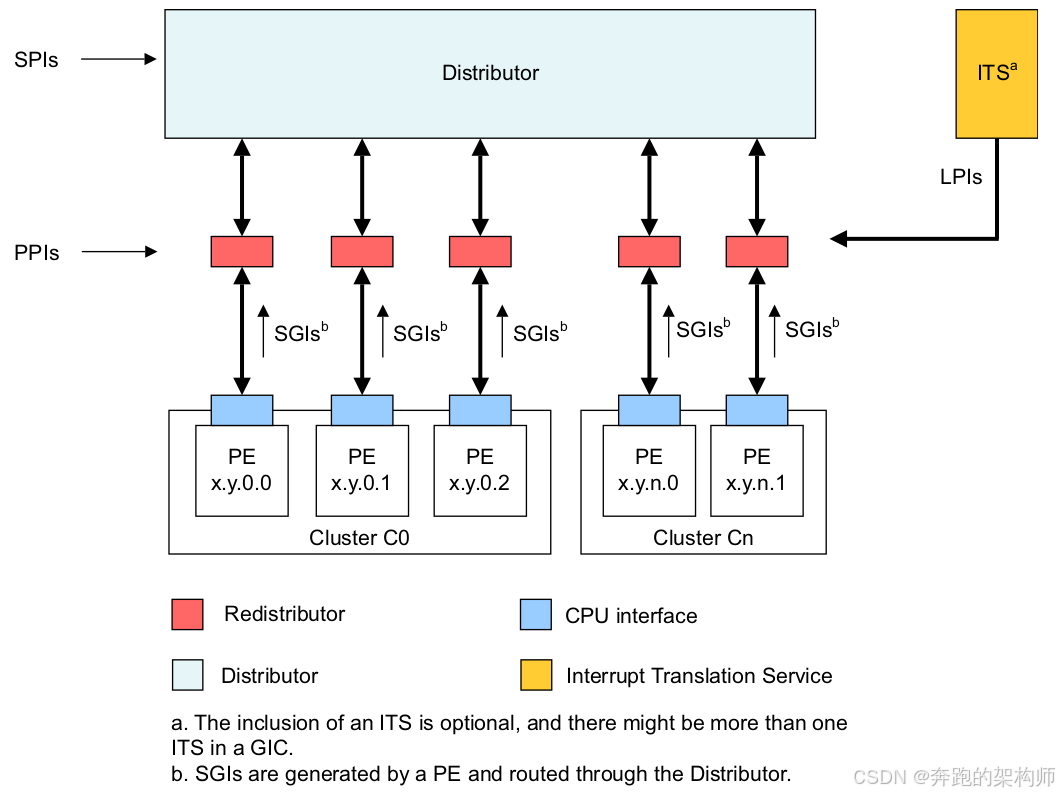
图1-13 GIC logical partitioning with an ITS
大家还要搞清楚一点,对于系统架构的学习没有明确的路线图,因人而异吧。看一下GIC子系统对于电源管理的描述,如果你对电源域的概念一点也不了解的话,硬看也挺痛苦,不过你了解了电源域基本概念后,再来看下面手册中的描述就应该很轻松了:
In an implementation compliant with the GICv3 architecture, the CPU interface and the PE must be in the same power domain, but this does not have to be the same power domain as that within which the associated Redistributor is located. This means that it is possible to have a situation where the PE and its CPU interface are powered down, and the Redistributor, Distributor, and ITS, are powered up. In this situation, the GIC architecture supports the use of interrupts targeted at the PE to signal a powerup event to the PE and CPU interface.
1.2.5 Implementation(PSCI-Sever) responsibilities
Suspend的参数介绍完了,下面就该是PSCI-Server登场了,主要需要做好四方面工作:
(1) State coordination
状态的融合和协调是PSCI机制的核心作用,这个前面的文章已经讨论过了就不展开了。根据不同的实现,各个芯片厂商应该会有有所差异,但是这部分最重要的工作就是为各个Level定义好电源状态之后,然后维护好一个电源状态机如图1-14所示:
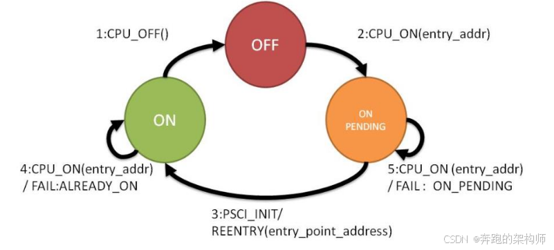
图1-14 PSCI implementation state machine
手册中给出了PE-Core的一组电源状态定义的示例:
As seen from the PSCI implementation, a core can be in any of the following states:
ON: This core has at some point been enabled with a call to CPU_ON , or is the cold boot primary core, and has not called CPU_OFF . In practice, the core might be running or in a low-power mode, either WFI or deeper because of a call to CPU_SUSPEND . The term ON reflects the fact that the core is considered to be available for computation.
OFF: This core has called CPU_OFF , and the call has been processed by the PSCI implementation, or the core has not been booted yet. The core is not available for computation.
ON_PENDING: CPU_ON has been called on the target core, but it is still in the process of booting and has not transitioned to an ON state.
(2)Interaction with a Trusted OS or SP
主要是提供一种能力给Security世界的朋友们,询问当前非安全世界的电源状态切换是否可以进行下去,这个我们也讨论过了。
(3)Cache and coherency management
这个先看下手册的描述:
Powerdown states generally require a cache clean. Prior to powering down a topology node, the PSCI implementation must perform a cache clean operation for all the caches present in that node, and the last children of that node that are being powered down. The implementation must also perform any required coherency management. In addition, the PSCI implementation needs to perform invalidation of caches on booting, unless this is automatically supported by the hardware, and to manage coherency. Sequences to be observed when powering cores up or down can be found in the Technical Reference Manuals for the relevant processors and interconnect IP.
要搞懂这一题,也是需要一些关于Cache的基础知识,如图1-15所示:
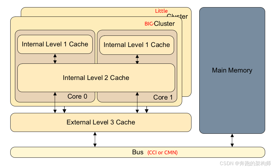
图1-15 ARM Big-Little Multi-Cache ARCH
ARM体系的CPU支持多级Cache架构,目的是为了更加高效的执行程序,装载和保存数据。Cache中的数据是内存中数据的副本,而内存中的数据根据作用的不同,在SOC层面可能是CPU和其他IP(GPU、ADSP、NPU等)之间的共享,在CPU层面可能是各个PE-Core之间共享。因此为了在电源状态切换的上下文保持数据的一致性,就需要对Cache进行响应的操作。这部分也不展开了,大家可以看我们前序的文章了解Cache相关的基础知识。
(4) State on return
再来看下Suspend接口的返回值:
When returning from a standby state, the caller must observe no change in core state, other than any timer changes expected because of the time spent in the state, and changes in the CPU interface because of the wakeup reason. To the core, a standby state is indistinguishable from the use of a WFI instruction. The only exceptions are the registers used in making the SMC call that follow the SMC
Calling Conventions 4. The return value expected in R0 or W0 is the return error code. For standby states, SUCCESS must be returned on success. Powerdown states do not return on success because restart is through the entry point address at wakeup. If not successful, the error code indicates the reason.
当OSPM中的PM软件模块调用PSCI_CPU_SUSPEND 接口后,不会立即返回,直到OSPM系统在当前PE-Core被重新唤醒。唤醒后,OSPM会得到一个返回值,然后PM模块可以据此判断唤醒原因(OSPM继续在该PE-Core执行的原因)并进行相应处理(成功或者失败,进入不同的分支继续处理)。
1.2.6 Suspend Work Flow
介绍完了Suspend接口的基本内容之后,我们再把视角拉高,从全局的角度再审视一下Suspend接口的工作流程,如图1-16所示:
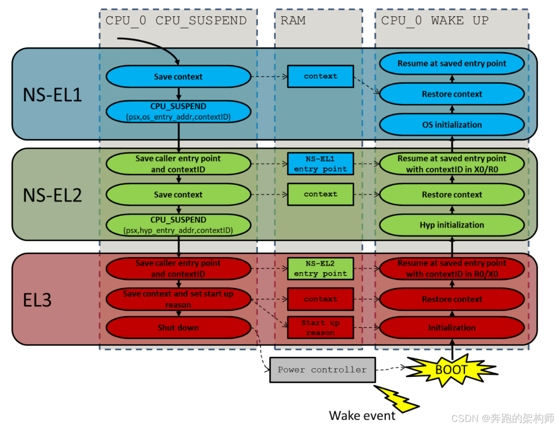
图1-16 Example call flow for a CPU_SUSPEND call
大家可以按照图上图把我们前面章节介绍的内容串联一下,应该会更加的清晰,这里我们就不展开讨论了。
结语
对PSCI接口规范以及工作流程的介绍就到这里。本文我们从PSCI接口的list开始,详细的讨论了PSCI在Caller和Callee两段的使用和实现过程中涉及的基础知识。通过一个具体的接口Suspend,展开讨论了接口使用过程中的Function ID,参数和返回值,并将Suspend的工作流程融汇其中,为大家做了梳理和总结。
对于PSCI机制的讨论暂时就告一段落了,要彻底理解PSCI需要大量的系统架构和软件操作系统以及虚拟化方面的基础知识,这些在我们的前序文章中都有涉猎。还有一点就是要注意,我们研究PSCI是为了用它为我们解决问题,所以大家搞清楚电源管理的背景也是非常的重要。注意一下PSCI覆盖仅仅是CPU各个PE-Core和PE-Core拓扑上各个PowerLevel上各个电源域的电源状态之间的协调工作。对于整个SOC层面的电源状态的协调其实还是要靠SCP完成,当然大部分情况下也需要OSPM中驱动程序的参与,可是这些参与的工作多数情况下都是各个IP的私有通路而不是PSCI通道,这一块其实也可以规范化,这也是未来我们研究的一块重要的领域。
今天就到这里,谢谢大家,请关注、转发、评论。
Reference
01 <DEN0050D_Power_Control_System_Architecture.pdf>
02 <armv8_a_power_management_100960_0100_en.pdf>
03 <Power_Policy_Unit_Architecture_Specification_0051E.pdf>
04 <DEN0024A_v8_architecture_PG.pdf>
05 <79-LX-LD-s003-Linux设备驱动开发详解4_0内核-3rd.pdf>
06 <80-PGxxx-35_QNX_Thermal_Manager_Overview.pdf>
07 <80-pgxxx-7_n_qnx_power_management_software_architecture_reference_manual.pdf>
08 <80-ARM-POWER-HK0001_一文搞懂ARM_SoC功耗控制架构.pdf>
09 <Arm_Power_and_Performance_Management_SCMI_White_Paper.pdf>
10 <80-ARM-POWER-cs0001_Arm-SoC-power功耗控制架构.pdf>
11 <80-LX-LK-cl0009_深入理解Linux电源管理.pdf>
12 <DEN0056D_System_Control_and_Management_Interface_v3_1.pdf>
13 <arm_total_compute_2021_reference_design_software_developer_guide_en.pdf>
14 <arm_total_compute_2022_reference_design_software_developer_guide_en.pdf>
15 <arm_cortex_m85_processor_trm_en.pdf>
16 <DEN0108_00eac0_smcf-archl-Specification.pdf>
17 <DEN0022F.b_Power_State_Coordination_Interface.pdf>
18 <MTxxxx_SCP_User_Manual_V1.0.pdf>
19 <learn_the_architecture_arm_system_architectures_en.pdf>
20 <arm_dsu_110_trm_101381_0400_11_en.pdf>
21 <DEN0077A_Firmware_Framework_Arm_A_profile_1.1_EAC0.pdf>
22 <80-LX-POWER-PSCI-cs0001_Linux-PSCI框架.pdf>
23 <learn_the_architecture_realm_management_extension_guide.pdf>
24 <ISA_A64_xml_A_profile-2024-03.pdf>
25 <learn_the_architecture_aarch64_memory_management_guide.pdf>
26 <IHI0069H_gic_architecture_specification.pdf>
Glossary
AP - application processor
OSPM - Operating System Power Management
WFI - Wait For Interrupt
WFE - Wait For Event
DVFS - Dynamic Voltage and Frequency Scaling
SCU - Snoop Control Unit
OPP - Operating Performance Point
PSCI - Power State Coordination Interface
PPU - Power Policy Unit
PCSA - Power Control System Architecture
SoC - System-on-Chip
PCF - Power Control Framework
SCP - System Control Processor
BSP - board support package
SCMI - System Control and Management Interface
EAS - Energy Aware Scheduling
IPA - Intelligent Power Allocation
ACPI - Advanced Configuration and Power Interface
LPI - Low-Power Idle
CPPC - Collaborative Processor Performance Control
PCSM - power control state machine
AOSS - Always-on subsystem
PMIC - Power Management Integrated Circuit
JM - job manager
AON - always on domain
SBSA - Server Base System Architecture
CLK_CTRL - Clock Controller
LPD - Low Power Distributor
LPC - Low Power Combiner
P2Q - P-Channel to Q-Channel Convertor
GPIO - General Purpose IO
RAS - Reliability, Availability, and Serviceability
STR - Suspend to RAM
SMCCC - SMC Calling Convention
RMM - Realm Management Monitor
BMC - board management controller
PPF - Privileged platform firmwarever
SPM - Secure Partition Manager
SP - Secure Partition