目录
- 1.问题描述
- 2.工程创建
- 3.将源文件中同名,命名进行替换
- 4.串口配置代码
-
- [4.1 串口1配置代码](#4.1 串口1配置代码)
-
- [4.1.1 bsp_debug.h](#4.1.1 bsp_debug.h)
- [4.1.2 bsp_debug.c](#4.1.2 bsp_debug.c)
- [4.1.3 app_debug.h](#4.1.3 app_debug.h)
- [4.1.4 app_debug.c](#4.1.4 app_debug.c)
- [4.2 串口3配置代码](#4.2 串口3配置代码)
-
- [4.2.1 bsp_device.h](#4.2.1 bsp_device.h)
- [4.2.2 bsp_device.c](#4.2.2 bsp_device.c)
- [4.2.3 app_device.h](#4.2.3 app_device.h)
- [4.2.4 app_device.c](#4.2.4 app_device.c)
- [5. 视频演示](#5. 视频演示)
1.问题描述
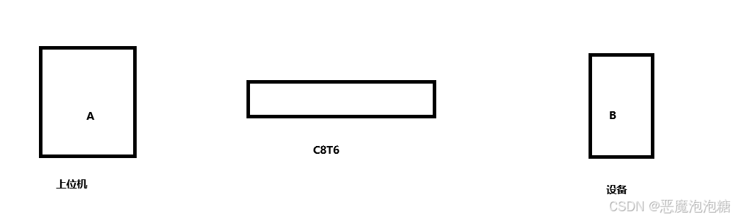
A上位机发送命令给C8T6,C8T6吧这些命令进行解析处理,然后吧这个指令给这个设备,设备去正常运行。而从A到C8T6使用的是一个串口接口,从C8T6到B也是一个串口接口,所以需要借助于C8T6这个媒介,B设备运行状态也可以通过串口传回给C8T6,C8T6将处理好的信息给上位机去显示,这相当于拥有两个串口。
A给C8T6,C8T6给B
B给C8T6,C8T6给A
2.工程创建
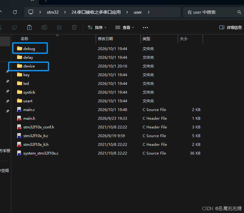
在user文件中将debug文件复制一份,文件名为device(设备),源文件命名更改为bsp_device.h和bsp_device.c
同时在app文件也一样做法
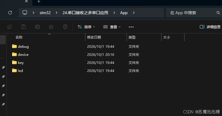
将debug文件复制一份,名字命名为device,源文件命名更改为app_device.h和app_device.c
最后将源文件添加到工程中去。
3.将源文件中同名,命名进行替换
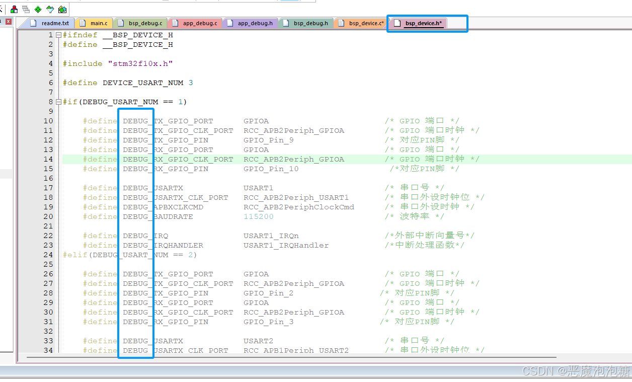
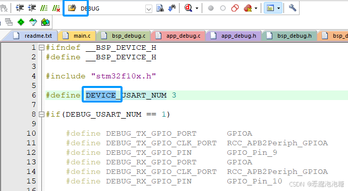
在这个文件中,将所有的DEBUG全部替换成DEVICE
1.CTRL+C复制USART,然后点击邮件图标
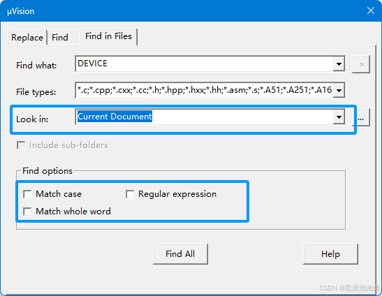
2.选择当前文件,勾选的地方全部去掉
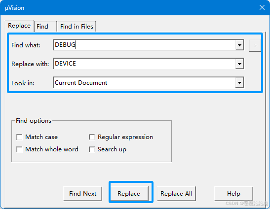
3.Find what填原来的变量名
Replace with 填替换后的名字
最后选择当前文件
点击Replace
4.最后会自动定位到DEBUG命名上,一直点击Replace不断替换。
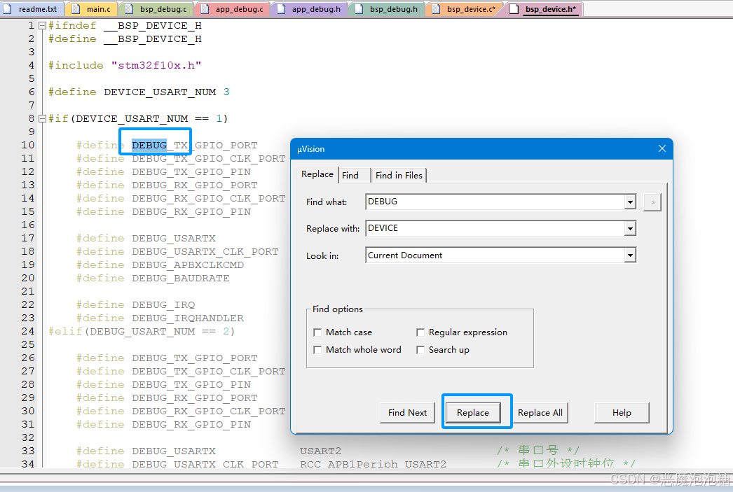
5.最终全部替换完成
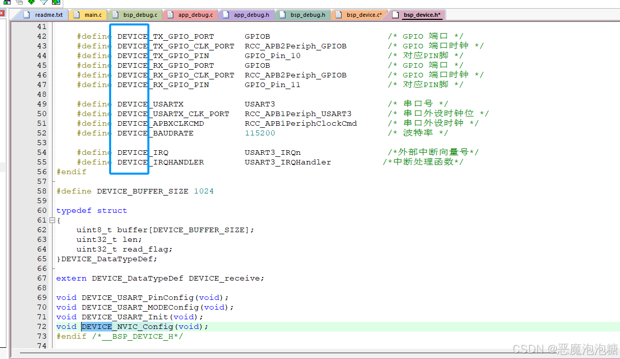
4.串口配置代码
串口3的配置代码就是将串口1的bsp源文件和头文件,以及app源文件的头文件复制一份,只是吧原本串口1名字DEBUG更改为device,然后device在bsp头文件中打开串口3的定义
核心部分:
在上位机中如果连接的是串口1,上位机发送数据,然后在代码中,将上位机发送的数据用数据保存起来,然后在串口1执行任务函数中,调用发送数据的函数,函数的第一个参数更改为串口3,这样就可以将数据发送到串口3
同样的,串口3接收数据,在任务函数中,发送数据函数第一个参数填串口1
4.1 串口1配置代码
4.1.1 bsp_debug.h
c
#ifndef __BSP_DEBUG_H
#define __BSP_DEBUG_H

#include "stm32f10x.h"

#define DEBUG_USART_NUM 1

#if(DEBUG_USART_NUM == 1)

    #define DEBUG_TX_GPIO_PORT      GPIOA                       /* GPIO 端口 */
    #define DEBUG_TX_GPIO_CLK_PORT  RCC_APB2Periph_GPIOA        /* GPIO 端口时钟 */
    #define DEBUG_TX_GPIO_PIN       GPIO_Pin_9                  /* 对应PIN脚 */
    #define DEBUG_RX_GPIO_PORT      GPIOA                       /* GPIO 端口 */
    #define DEBUG_RX_GPIO_CLK_PORT  RCC_APB2Periph_GPIOA        /* GPIO 端口时钟 */
    #define DEBUG_RX_GPIO_PIN       GPIO_Pin_10                  /*对应PIN脚 */

    #define DEBUG_USARTX            USART1                      /* 串口号 */
    #define DEBUG_USARTX_CLK_PORT   RCC_APB2Periph_USART1       /* 串口外设时钟位 */
    #define DEBUG_APBXCLKCMD        RCC_APB2PeriphClockCmd      /* 串口外设时钟 */
    #define DEBUG_BAUDRATE          115200                      /* 波特率 */

    #define DEBUG_IRQ               USART1_IRQn                 /*外部中断向量号*/
    #define DEBUG_IRQHANDLER        USART1_IRQHandler           /*中断处理函数*/
#elif(DEBUG_USART_NUM == 2)

    #define DEBUG_TX_GPIO_PORT      GPIOA                       /* GPIO 端口 */
    #define DEBUG_TX_GPIO_CLK_PORT  RCC_APB2Periph_GPIOA        /* GPIO 端口时钟 */
    #define DEBUG_TX_GPIO_PIN       GPIO_Pin_2                 /* 对应PIN脚 */
    #define DEBUG_RX_GPIO_PORT      GPIOA                       /* GPIO 端口 */
    #define DEBUG_RX_GPIO_CLK_PORT  RCC_APB2Periph_GPIOA        /* GPIO 端口时钟 */
    #define DEBUG_RX_GPIO_PIN       GPIO_Pin_3                 /* 对应PIN脚 */

    #define DEBUG_USARTX            USART2                      /* 串口号 */
    #define DEBUG_USARTX_CLK_PORT   RCC_APB1Periph_USART2       /* 串口外设时钟位 */
    #define DEBUG_APBXCLKCMD        RCC_APB1PeriphClockCmd      /* 串口外设时钟 */
    #define DEBUG_BAUDRATE          115200                      /* 波特率 */

    #define DEBUG_IRQ               USART2_IRQn                 /*外部中断向量号*/
    #define DEBUG_IRQHANDLER        USART2_IRQHandler          /*中断处理函数*/
#elif(DEBUG_USART_NUM == 3)

    #define DEBUG_TX_GPIO_PORT      GPIOB                       /* GPIO 端口 */
    #define DEBUG_TX_GPIO_CLK_PORT  RCC_APB2Periph_GPIOB        /* GPIO 端口时钟 */
    #define DEBUG_TX_GPIO_PIN       GPIO_Pin_10                 /* 对应PIN脚 */
    #define DEBUG_RX_GPIO_PORT      GPIOB                       /* GPIO 端口 */
    #define DEBUG_RX_GPIO_CLK_PORT  RCC_APB2Periph_GPIOB        /* GPIO 端口时钟 */
    #define DEBUG_RX_GPIO_PIN       GPIO_Pin_11                 /* 对应PIN脚 */

    #define DEBUG_USARTX            USART3                      /* 串口号 */
    #define DEBUG_USARTX_CLK_PORT   RCC_APB1Periph_USART3       /* 串口外设时钟位 */
    #define DEBUG_APBXCLKCMD        RCC_APB1PeriphClockCmd      /* 串口外设时钟 */
    #define DEBUG_BAUDRATE          115200                      /* 波特率 */

    #define DEBUG_IRQ               USART3_IRQn                 /*外部中断向量号*/
    #define DEBUG_IRQHANDLER        USART3_IRQHandler          /*中断处理函数*/
#endif

#define DEBUG_BUFFER_SIZE 1024

typedef struct
{
    uint8_t buffer[DEBUG_BUFFER_SIZE];
    uint32_t len;
    uint32_t read_flag;
}DEBUG_DataTypeDef;

extern DEBUG_DataTypeDef debug_receive;

void DEBUG_USART_PinConfig(void);
void DEBUG_USART_MODEConfig(void);
void DEBUG_USART_Init(void);
void DEBUG_NVIC_Config(void);
#endif /*__BSP_DEBUG_H*/
4.1.2 bsp_debug.c
c
/**
  ******************************************************************************
  * @file    bsp_debug.c
  * @author  作者
  * @version v1.0
  * @date    2026.6.6
  * @brief   调试串口函数接口
  ******************************************************************************
  * @attention
  *
  * 版权声明
  *
  ******************************************************************************
  */
#include "debug/bsp_debug.h"
#include "usart/usart_com.h"

DEBUG_DataTypeDef debug_receive = { 0 };

/**
  * @brief  初始化控制 DEBUG 串口 的IO
  * @param  无
  * @retval 无
  */

void DEBUG_USART_PinConfig(void)
{
    GPIO_InitTypeDef GPIO_InitStruct = { 0 };

#if 1
    /*对串口发送模式IO配置*/
    /* 开启 DEBUG 相关的GPIO外设/端口时钟 */
    RCC_APB2PeriphClockCmd(DEBUG_TX_GPIO_CLK_PORT, ENABLE); //开启GPIOA 端口时钟

    // 配置引脚:选择GPIOA的Pin9
    GPIO_InitStruct.GPIO_Pin = DEBUG_TX_GPIO_PIN;
    // 配置输出速度:50MHz
    GPIO_InitStruct.GPIO_Speed = GPIO_Speed_50MHz;
    // 配置工作模式:推挽复用
    GPIO_InitStruct.GPIO_Mode = GPIO_Mode_AF_PP;
    GPIO_Init(DEBUG_TX_GPIO_PORT, &GPIO_InitStruct);
#endif

#if 1
    /*对串口接收模式IO配置*/
    /* 开启 DEBUG 相关的GPIO外设/端口时钟 */
    RCC_APB2PeriphClockCmd(DEBUG_RX_GPIO_CLK_PORT, ENABLE); //开启GPIOA 端口时钟

    // 配置引脚:选择GPIOA的Pin10
    GPIO_InitStruct.GPIO_Pin = DEBUG_RX_GPIO_PIN;
    // 配置输出速度:50MHz
    GPIO_InitStruct.GPIO_Speed = GPIO_Speed_50MHz;
    // 配置工作模式:上拉输入/浮空输入
    GPIO_InitStruct.GPIO_Mode = GPIO_Mode_IPU;
    GPIO_Init(DEBUG_RX_GPIO_PORT, &GPIO_InitStruct);
#endif

}

/**
  * @brief  配置 DEBUG 串口模式
  * @param  无
  * @retval 无
  */

void DEBUG_USART_MODEConfig(void)
{
    USART_InitTypeDef usart_InitStruct = { 0 };

    /* 开启 DEBUG 相关的GPIO外设/端口时钟 */
    DEBUG_APBXCLKCMD(DEBUG_USARTX_CLK_PORT, ENABLE); //开启 端口时钟

    /* 配置串口的工作参数 */

    //波特率配置:115200
    usart_InitStruct.USART_BaudRate            = DEBUG_BAUDRATE;
    //硬件流控开关配置:无
    usart_InitStruct.USART_HardwareFlowControl = USART_HardwareFlowControl_None;
    //配置工作模式:发送模式和接收模式
    usart_InitStruct.USART_Mode                = USART_Mode_Tx | USART_Mode_Rx;
    //校验:无校验位
    usart_InitStruct.USART_Parity              = USART_Parity_No;
    //停止位:1个停止位
    usart_InitStruct.USART_StopBits            = USART_StopBits_1;
    //数据帧长度:8位
    usart_InitStruct.USART_WordLength          = USART_WordLength_8b;

    USART_Init(DEBUG_USARTX, &usart_InitStruct);

    /* 开启串口数据接收中断 */
    USART_ITConfig(DEBUG_USARTX, USART_IT_RXNE, ENABLE);
    /* 开启串口数据空闲中断 */
    USART_ITConfig(DEBUG_USARTX, USART_IT_IDLE, ENABLE);
}

/**
  * @brief  配置 DEBUG 中断配置
  * @param  无
  * @retval 无
  */
void DEBUG_NVIC_Config()
{
    // 定义一个 NVIC 结构体
    NVIC_InitTypeDef nvic_initstauct = { 0 };

    /* 开启 AFIO 相关时钟 */
    RCC_APB2PeriphClockCmd(RCC_APB2Periph_AFIO, ENABLE);

    /*配置中断源*/
    nvic_initstauct.NVIC_IRQChannel                   = DEBUG_IRQ;
    /*配置抢占优先级*/
    nvic_initstauct.NVIC_IRQChannelPreemptionPriority = 1;
    /*配置响应优先级*/
    nvic_initstauct.NVIC_IRQChannelSubPriority        = 0;
    /*开启中断*/
    nvic_initstauct.NVIC_IRQChannelCmd                = ENABLE;

    // 把配置写入硬件,生效
    NVIC_Init(&nvic_initstauct);
}

/**
  * @brief  DEBUG 串口初始化
  * @param  无
  * @retval 无
  */
void DEBUG_USART_Init(void)
{
    /* 配置 DEBUG 中断配置 */
    DEBUG_NVIC_Config();

    /*配置 DEBUG 串口模式*/
    DEBUG_USART_MODEConfig();

    /* 串口 GPIO 配置 */
    DEBUG_USART_PinConfig();

    /* 串口使能 */
    USART_Cmd(DEBUG_USARTX, ENABLE);
}

/*
1.因为数组下标从0开始的,定义buffer[DEBUG_BUFFER_SIZE]时,可取的末尾是buffer[DEBUG_BUFFER_SIZE - 1];

2.因为数组下标从0开始接收,当接收了len个,buffer[len-1]为最近一次保存位置,buffer[len]指向的是下一个准备接收空位,所以用len与DEBUG_BUFFER_SIZE-1比较

*/
/**
  * @brief  DEBUG 串口中断 回调函数
  * @param  无
  * @retval 无
  */
void DEBUG_IRQHANDLER(void)
{
    uint8_t data_temp = NULL;

    /* 数据回显 */
    if (USART_GetITStatus(DEBUG_USARTX, USART_IT_RXNE) == SET)
    {
        //读取数据寄存器,读取后对应的寄存器会被复位
        data_temp = USART_ReceiveData(DEBUG_USARTX);
        /*当存储数据的数组没有满 并且 是空闲状态可以接收*/
        if ((debug_receive.len < DEBUG_BUFFER_SIZE - 1) && (debug_receive.read_flag == 0))
        {
            debug_receive.buffer[debug_receive.len] = data_temp;
            debug_receive.len++;
        }
        /*满数据包*/
        if (debug_receive.len == DEBUG_BUFFER_SIZE - 1)
        {
            debug_receive.buffer[debug_receive.len] = '\0';
            debug_receive.read_flag = 1;
        }
//        USART_SenByte(DEBUG_USARTX, data_temp);
        USART_ClearITPendingBit(DEBUG_USARTX, USART_IT_RXNE);       //清除接收标志位
    }

    /*
        串口检测到「一帧数据传输完毕,总线上持续一段时间没有新字节」,就触发空闲中断
        用来做数据结束
    */
    // 检测空闲中断
    if (USART_GetITStatus(DEBUG_USARTX, USART_IT_IDLE) == SET)
    {
        /*
            根据手册实际描述(读取获取USART_ITIDLE、数据寄存器的数据,读取后对应的寄存器会被复位)
            用这样方式清除IDLE

            清除标志位过程
            1.获取中断状态USART_GetITStatus()
            2.读取数据寄存器数据USART_ReceiveData()
            最终将DEBUG_USARTX标志位清除
        */
        USART_ReceiveData(DEBUG_USARTX);//用来清除空闲中断标志位USART_IT_IDLE

        debug_receive.buffer[debug_receive.len] = '\0';
        debug_receive.read_flag = 1;
    }
}


/***************************************END OF FILE *********************************************************/
4.1.3 app_debug.h
c
#ifndef __APP_DEBUG_H
#define __APP_DEBUG_H

#include "stm32f10x.h"

void DEBUG_ReadBufferReset(void);
void DEBUG_TaskInit(void);
void DEBUG_Task(void);
//void DEBUG_Show_Message(void);
#endif /*__APP_DEBUG_H*/
4.1.4 app_debug.c
c
/**
  ******************************************************************************
  * @file    App_debug.c
  * @author  作者
  * @version v1.0
  * @date    2026.9.22
  * @brief   DEBUG 串口 应用层功能接口
  ******************************************************************************
  * @attention
  *
  * 版权声明
  *
  ******************************************************************************
  */
#include "debug/bsp_debug.h"
#include "debug/app_debug.h"
#include "device/bsp_device.h"
#include "usart/usart_com.h"
#include <string.h>

/**
  * @brief  DEBUG串口 接收缓存区复位
  * @param  无
  * @retval 无
  */
void DEBUG_ReadBufferReset(void)
{
    memset(debug_receive.buffer, NULL, debug_receive.len);
    debug_receive.len = 0;
    debug_receive.read_flag = 0;
}

/**
  * @brief  DEBUG串口 任务初始化
  * @param  无
  * @retval 无
  */
void DEBUG_TaskInit(void)
{
    DEBUG_ReadBufferReset();
    //DEBUG_Show_Message();
}

///**
//  * @brief  打印指令输入提示信息
//  * @param  无
//  * @retval 无
//  */
//void DEBUG_Show_Message(void)
//{
//    printf("\r\n这是一个通过串口通信指令控制G/B实验\n");
//    printf("使用USART参数为:%d 8-N-1\n",DEBUG_BAUDRATE);
//    printf("开发板接到指令后控制G/B灯,指令对应如下(以\\n结束):\n");
//    printf("   指令   ------ 彩灯颜色\n");
//    printf("GREEN=ON  ------ 绿灯亮\n");
//    printf("GREEN=OFF ------ 绿灯灭\n");
//    printf("BLUE=ON   ------ 蓝灯亮\n");
//    printf("BLUE=OFF  ------ 蓝灯灭\n");
//}

/**
  * @brief  DEBUG串口 任务
  * @param  无
  * @retval 无
  */
void DEBUG_Task(void)
{
    if (debug_receive.read_flag)
    {
        USART_SenString(DEVICE_USARTX, "MCU已经接收DEBUG串口数据:");
        USART_SenArray(DEVICE_USARTX, debug_receive.buffer, debug_receive.len);

        DEBUG_ReadBufferReset();
    }

}

/***************************************END OF FILE *********************************************************/
4.2 串口3配置代码
4.2.1 bsp_device.h
c
#ifndef __BSP_DEVICE_H
#define __BSP_DEVICE_H

#include "stm32f10x.h"

#define DEVICE_USART_NUM 3

#if(DEVICE_USART_NUM == 1)

    #define DEVICE_TX_GPIO_PORT      GPIOA                       /* GPIO 端口 */
    #define DEVICE_TX_GPIO_CLK_PORT  RCC_APB2Periph_GPIOA        /* GPIO 端口时钟 */
    #define DEVICE_TX_GPIO_PIN       GPIO_Pin_9                  /* 对应PIN脚 */
    #define DEVICE_RX_GPIO_PORT      GPIOA                       /* GPIO 端口 */
    #define DEVICE_RX_GPIO_CLK_PORT  RCC_APB2Periph_GPIOA        /* GPIO 端口时钟 */
    #define DEVICE_RX_GPIO_PIN       GPIO_Pin_10                  /*对应PIN脚 */

    #define DEVICE_USARTX            USART1                      /* 串口号 */
    #define DEVICE_USARTX_CLK_PORT   RCC_APB2Periph_USART1       /* 串口外设时钟位 */
    #define DEVICE_APBXCLKCMD        RCC_APB2PeriphClockCmd      /* 串口外设时钟 */
    #define DEVICE_BAUDRATE          115200                      /* 波特率 */

    #define DEVICE_IRQ               USART1_IRQn                 /*外部中断向量号*/
    #define DEVICE_IRQHANDLER        USART1_IRQHandler           /*中断处理函数*/
#elif(DEVICE_USART_NUM == 2)

    #define DEVICE_TX_GPIO_PORT      GPIOA                       /* GPIO 端口 */
    #define DEVICE_TX_GPIO_CLK_PORT  RCC_APB2Periph_GPIOA        /* GPIO 端口时钟 */
    #define DEVICE_TX_GPIO_PIN       GPIO_Pin_2                 /* 对应PIN脚 */
    #define DEVICE_RX_GPIO_PORT      GPIOA                       /* GPIO 端口 */
    #define DEVICE_RX_GPIO_CLK_PORT  RCC_APB2Periph_GPIOA        /* GPIO 端口时钟 */
    #define DEVICE_RX_GPIO_PIN       GPIO_Pin_3                 /* 对应PIN脚 */

    #define DEVICE_USARTX            USART2                      /* 串口号 */
    #define DEVICE_USARTX_CLK_PORT   RCC_APB1Periph_USART2       /* 串口外设时钟位 */
    #define DEVICE_APBXCLKCMD        RCC_APB1PeriphClockCmd      /* 串口外设时钟 */
    #define DEVICE_BAUDRATE          115200                      /* 波特率 */

    #define DEVICE_IRQ               USART2_IRQn                 /*外部中断向量号*/
    #define DEVICE_IRQHANDLER        USART2_IRQHandler          /*中断处理函数*/
#elif(DEVICE_USART_NUM == 3)

    #define DEVICE_TX_GPIO_PORT      GPIOB                       /* GPIO 端口 */
    #define DEVICE_TX_GPIO_CLK_PORT  RCC_APB2Periph_GPIOB        /* GPIO 端口时钟 */
    #define DEVICE_TX_GPIO_PIN       GPIO_Pin_10                 /* 对应PIN脚 */
    #define DEVICE_RX_GPIO_PORT      GPIOB                       /* GPIO 端口 */
    #define DEVICE_RX_GPIO_CLK_PORT  RCC_APB2Periph_GPIOB        /* GPIO 端口时钟 */
    #define DEVICE_RX_GPIO_PIN       GPIO_Pin_11                 /* 对应PIN脚 */

    #define DEVICE_USARTX            USART3                      /* 串口号 */
    #define DEVICE_USARTX_CLK_PORT   RCC_APB1Periph_USART3       /* 串口外设时钟位 */
    #define DEVICE_APBXCLKCMD        RCC_APB1PeriphClockCmd      /* 串口外设时钟 */
    #define DEVICE_BAUDRATE          115200                      /* 波特率 */

    #define DEVICE_IRQ               USART3_IRQn                 /*外部中断向量号*/
    #define DEVICE_IRQHANDLER        USART3_IRQHandler          /*中断处理函数*/
#endif

#define DEVICE_BUFFER_SIZE 1024

typedef struct
{
    uint8_t buffer[DEVICE_BUFFER_SIZE];
    uint32_t len;
    uint32_t read_flag;
}DEVICE_DataTypeDef;

extern DEVICE_DataTypeDef device_receive;

void DEVICE_USART_PinConfig(void);
void DEVICE_USART_MODEConfig(void);
void DEVICE_USART_Init(void);
void DEVICE_NVIC_Config(void);
#endif /*__BSP_DEVICE_H*/
4.2.2 bsp_device.c
c
/**
  ******************************************************************************
  * @file    bsp_device.c
  * @author  作者
  * @version v1.0
  * @date    2026.10.1
  * @brief   外部设备串口函数接口
  ******************************************************************************
  * @attention
  *
  * 版权声明
  *
  ******************************************************************************
  */
#include "device/bsp_device.h"
#include "usart/usart_com.h"

DEVICE_DataTypeDef device_receive = { 0 };

/**
  * @brief  初始化控制 DEVICE 串口 的IO
  * @param  无
  * @retval 无
  */

void DEVICE_USART_PinConfig(void)
{
    GPIO_InitTypeDef GPIO_InitStruct = { 0 };

#if 1
    /*对串口发送模式IO配置*/
    /* 开启 DEVICE 相关的GPIO外设/端口时钟 */
    RCC_APB2PeriphClockCmd(DEVICE_TX_GPIO_CLK_PORT, ENABLE); //开启GPIOA 端口时钟

    // 配置引脚:选择GPIOB的Pin10
    GPIO_InitStruct.GPIO_Pin = DEVICE_TX_GPIO_PIN;
    // 配置输出速度:50MHz
    GPIO_InitStruct.GPIO_Speed = GPIO_Speed_50MHz;
    // 配置工作模式:推挽复用
    GPIO_InitStruct.GPIO_Mode = GPIO_Mode_AF_PP;
    GPIO_Init(DEVICE_TX_GPIO_PORT, &GPIO_InitStruct);
#endif

#if 1
    /*对串口接收模式IO配置*/
    /* 开启 DEVICE 相关的GPIO外设/端口时钟 */
    RCC_APB2PeriphClockCmd(DEVICE_RX_GPIO_CLK_PORT, ENABLE); //开启GPIOA 端口时钟

    // 配置引脚:选择GPIOB的Pin11
    GPIO_InitStruct.GPIO_Pin = DEVICE_RX_GPIO_PIN;
    // 配置输出速度:50MHz
    GPIO_InitStruct.GPIO_Speed = GPIO_Speed_50MHz;
    // 配置工作模式:上拉输入/浮空输入
    GPIO_InitStruct.GPIO_Mode = GPIO_Mode_IPU;
    GPIO_Init(DEVICE_RX_GPIO_PORT, &GPIO_InitStruct);
#endif

}

/**
  * @brief  配置 DEVICE 串口模式
  * @param  无
  * @retval 无
  */

void DEVICE_USART_MODEConfig(void)
{
    USART_InitTypeDef usart_InitStruct = { 0 };

    /* 开启 DEVICE 相关的GPIO外设/端口时钟 */
    DEVICE_APBXCLKCMD(DEVICE_USARTX_CLK_PORT, ENABLE); //开启 端口时钟

    /* 配置串口的工作参数 */

    //波特率配置:115200
    usart_InitStruct.USART_BaudRate            = DEVICE_BAUDRATE;
    //硬件流控开关配置:无
    usart_InitStruct.USART_HardwareFlowControl = USART_HardwareFlowControl_None;
    //配置工作模式:发送模式和接收模式
    usart_InitStruct.USART_Mode                = USART_Mode_Tx | USART_Mode_Rx;
    //校验:无校验位
    usart_InitStruct.USART_Parity              = USART_Parity_No;
    //停止位:1个停止位
    usart_InitStruct.USART_StopBits            = USART_StopBits_1;
    //数据帧长度:8位
    usart_InitStruct.USART_WordLength          = USART_WordLength_8b;

    USART_Init(DEVICE_USARTX, &usart_InitStruct);

    /* 开启串口数据接收中断 */
    USART_ITConfig(DEVICE_USARTX, USART_IT_RXNE, ENABLE);
    /* 开启串口数据空闲中断 */
    USART_ITConfig(DEVICE_USARTX, USART_IT_IDLE, ENABLE);
}

/**
  * @brief  配置 DEVICE 中断配置
  * @param  无
  * @retval 无
  */
void DEVICE_NVIC_Config()
{
    // 定义一个 NVIC 结构体
    NVIC_InitTypeDef nvic_initstauct = { 0 };

    /* 开启 AFIO 相关时钟 */
    RCC_APB2PeriphClockCmd(RCC_APB2Periph_AFIO, ENABLE);

    /*配置中断源*/
    nvic_initstauct.NVIC_IRQChannel                   = DEVICE_IRQ;
    /*配置抢占优先级*/
    nvic_initstauct.NVIC_IRQChannelPreemptionPriority = 1;
    /*配置响应优先级*/
    nvic_initstauct.NVIC_IRQChannelSubPriority        = 0;
    /*开启中断*/
    nvic_initstauct.NVIC_IRQChannelCmd                = ENABLE;

    // 把配置写入硬件,生效
    NVIC_Init(&nvic_initstauct);
}

/**
  * @brief  DEVICE 串口初始化
  * @param  无
  * @retval 无
  */
void DEVICE_USART_Init(void)
{
    /* 配置 DEVICE 中断配置 */
    DEVICE_NVIC_Config();

    /*配置 DEVICE 串口模式*/
    DEVICE_USART_MODEConfig();

    /* 串口 GPIO 配置 */
    DEVICE_USART_PinConfig();

    /* 串口使能 */
    USART_Cmd(DEVICE_USARTX, ENABLE);
}

/*
1.因为数组下标从0开始的,定义buffer[DEVICE_BUFFER_SIZE]时,可取的末尾是buffer[DEVICE_BUFFER_SIZE - 1];

2.因为数组下标从0开始接收,当接收了len个,buffer[len-1]为最近一次保存位置,buffer[len]指向的是下一个准备接收空位,所以用len与DEVICE_BUFFER_SIZE-1比较

*/
/**
  * @brief  DEVICE 串口中断 回调函数
  * @param  无
  * @retval 无
  */
void DEVICE_IRQHANDLER(void)
{
    uint8_t data_temp = NULL;

    /* 数据回显 */
    if (USART_GetITStatus(DEVICE_USARTX, USART_IT_RXNE) == SET)
    {
        //读取数据寄存器,读取后对应的寄存器会被复位
        data_temp = USART_ReceiveData(DEVICE_USARTX);
        /*当存储数据的数组没有满 并且 是空闲状态可以接收*/
        if ((device_receive.len < DEVICE_BUFFER_SIZE - 1) && (device_receive.read_flag == 0))
        {
            device_receive.buffer[device_receive.len] = data_temp;
            device_receive.len++;
        }
        /*满数据包*/
        if (device_receive.len == DEVICE_BUFFER_SIZE - 1)
        {
            device_receive.buffer[device_receive.len] = '\0';
            device_receive.read_flag = 1;
        }
//        USART_SenByte(DEVICE_USARTX, data_temp);
        USART_ClearITPendingBit(DEVICE_USARTX, USART_IT_RXNE);       //清除接收标志位
    }

    /*
        串口检测到「一帧数据传输完毕,总线上持续一段时间没有新字节」,就触发空闲中断
        用来做数据结束
    */
    // 检测空闲中断
    if (USART_GetITStatus(DEVICE_USARTX, USART_IT_IDLE) == SET)
    {
        /*
            根据手册实际描述(读取获取USART_ITIDLE、数据寄存器的数据,读取后对应的寄存器会被复位)
            用这样方式清除IDLE

            清除标志位过程
            1.获取中断状态USART_GetITStatus()
            2.读取数据寄存器数据USART_ReceiveData()
            最终将DEVICE_USARTX标志位清除
        */
        USART_ReceiveData(DEVICE_USARTX);//用来清除空闲中断标志位USART_IT_IDLE

        device_receive.buffer[device_receive.len] = '\0';
        device_receive.read_flag = 1;
    }
}


/***************************************END OF FILE *********************************************************/
4.2.3 app_device.h
c
#ifndef __APP_DEVICE_H
#define __APP_DEVICE_H

#include "stm32f10x.h"

void DEVICE_ReadBufferReset(void);
void DEVICE_TaskInit(void);
void DEVICE_Task(void);
//void DEVICE_Show_Message();
#endif /*__APP_DEVICE_H*/
4.2.4 app_device.c
c
/**
  ******************************************************************************
  * @file    App_device.c
  * @author  作者
  * @version v1.0
  * @date    2026.9.22
  * @brief   外部设备串口 应用层功能接口
  ******************************************************************************
  * @attention
  *
  * 版权声明
  *
  ******************************************************************************
  */
#include "device/bsp_device.h"
#include "device/app_device.h"
#include "debug/bsp_debug.h"
#include "usart/usart_com.h"
#include <string.h>

/**
  * @brief  DEVICE串口 接收缓存区复位
  * @param  无
  * @retval 无
  */
void DEVICE_ReadBufferReset(void)
{
    memset(device_receive.buffer, NULL, device_receive.len);
    device_receive.len = 0;
    device_receive.read_flag = 0;
}

/**
  * @brief  DEVICE串口 任务初始化
  * @param  无
  * @retval 无
  */
void DEVICE_TaskInit(void)
{
    DEVICE_ReadBufferReset();
    //DEVICE_Show_Message();
}

///**
//  * @brief  打印指令输入提示信息
//  * @param  无
//  * @retval 无
//  */
//void DEVICE_Show_Message(void)
//{
//    printf("\r\n这是一个通过串口通信指令控制G/B实验\n");
//    printf("使用USART参数为:%d 8-N-1\n",DEVICE_BAUDRATE);
//    printf("开发板接到指令后控制G/B灯,指令对应如下(以\\n结束):\n");
//    printf("   指令   ------ 彩灯颜色\n");
//    printf("GREEN=ON  ------ 绿灯亮\n");
//    printf("GREEN=OFF ------ 绿灯灭\n");
//    printf("BLUE=ON   ------ 蓝灯亮\n");
//    printf("BLUE=OFF  ------ 蓝灯灭\n");
//}

/**
  * @brief  DEVICE串口 任务
  * @param  无
  * @retval 无
  */
void DEVICE_Task(void)
{
    if (device_receive.read_flag)
    {
        USART_SenString(DEBUG_USARTX, "MCU已经接收外部设备串口数据:");
        USART_SenArray(DEBUG_USARTX, device_receive.buffer, device_receive.len);


        DEVICE_ReadBufferReset();
    }

}

/***************************************END OF FILE *********************************************************/
5. 视频演示
多串口基础应用
串口1
TX PA9
RX PA10
串口2
TX PB10
RX PB11
例如如果想要两个设备相互传输,A设备发送数据给B设备,B设备也可以发送数据给A设备
本次实验通过借助C8T6作为中间媒介
设备A发送数据给C8T6,C8T6通过PA10引脚接收数据,通过串口2的PB10发送数据给设备B
设备B发送数据给C8T6,C8T6通过PB11引I脚接收数据,通过串口1的PA9发送数据给设备A