Arduino - Light Sensor
In this tutorial, we are going to learn:
在本教程中,我们将学习:
- How light sensor works 光传感器的工作原理
- How to connect the light sensor to Arduino
如何将光传感器连接到Arduino - How to program Arduino to read the state from the light sensor
如何对Arduino进行编程以从光传感器读取状态
If you are looking for a light sensor in the module form, please check out this Arduino - LDR Light Sensor Module tutorial.
如果您正在寻找模块形式的光传感器,请查看此 Arduino - LDR 光传感器模块教程。
Hardware Required 所需硬件
| 1 | × | Arduino UNO or Genuino UNO Arduino UNO 或 Genuino UNO | |
|---|---|---|---|
| 1 | × | USB 2.0 cable type A/B USB 2.0 电缆 A/B 型 | |
| 1 | × | Light Sensor 光传感器 | |
| 1 | × | 10 kΩ resistor 10 kΩ 电阻 | |
About Light Sensor 关于光传感器
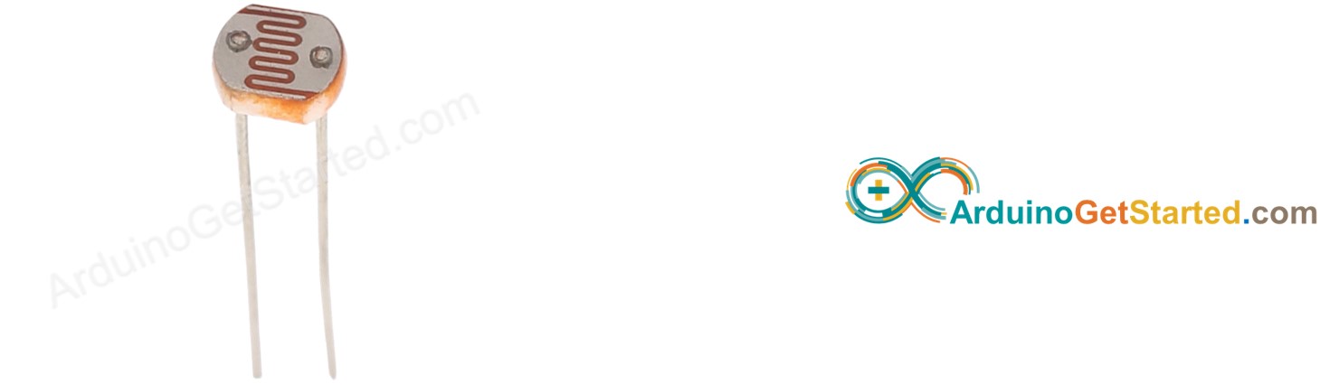
The light sensor used in this tutorial is a photoresistor, which is also called light-dependent resistor or photocell.
本教程中使用的光传感器是光敏电阻,也称为光敏电阻或光电管。
It is used not only to detect light but also to measure the brightness/illuminance level of the ambient light.
它不仅用于检测光,还用于测量环境光的亮度/照度水平。
Pinout 引脚排列
A photoresistor has two pins. Since it is a kind of resistor, we do NOT need to distinguish these pins. They are symmetric.
光敏电阻有两个引脚。由于它是一种电阻器,因此我们不需要区分这些引脚。它们是对称的。
How It Works 它是如何工作的
The more light the photoresistor's face is exposed, the smaller its resistance is. Therefore, by measuring the photoresistor's resistance, we can know how bright the ambient light is.
光敏电阻表面暴露的光线越多,其电阻就越小。因此,通过测量光敏电阻的电阻,我们可以知道环境光的亮度。
WARNING
The light sensor value only reflects the approximated trend of the intensity of light, it does NOT represent the exact luminous flux. Therefore, it should be used only in an application that does NOT require high accuracy.
光传感器值仅反映光强度的近似趋势,并不代表确切的光通量。因此,它应该只用于不需要高精度的应用。
Arduino - Light Sensor Arduino - 光传感器
Arduino Uno's pin A0 to A5 can work as the analog input. The analog input pin converts the voltage (between 0v and VCC ) into integer values (between 0 and 1023), called ADC value or analog value.
Arduino Uno 的引脚 A0 到 A5 可以用作模拟输入。模拟输入引脚将电压(0v和VCC之间)转换为整数值(0到1023之间),称为ADC值或模拟值。
By connecting a pin of the photoresistor to an analog input pin, we can read the analog value from the pin by using analogRead() function, and then we can know the light levels relatively.
通过将光敏电阻的引脚连接到模拟输入引脚,我们可以使用 analogRead() 函数从引脚读取模拟值,然后我们可以相对地知道光照水平。
Wiring Diagram
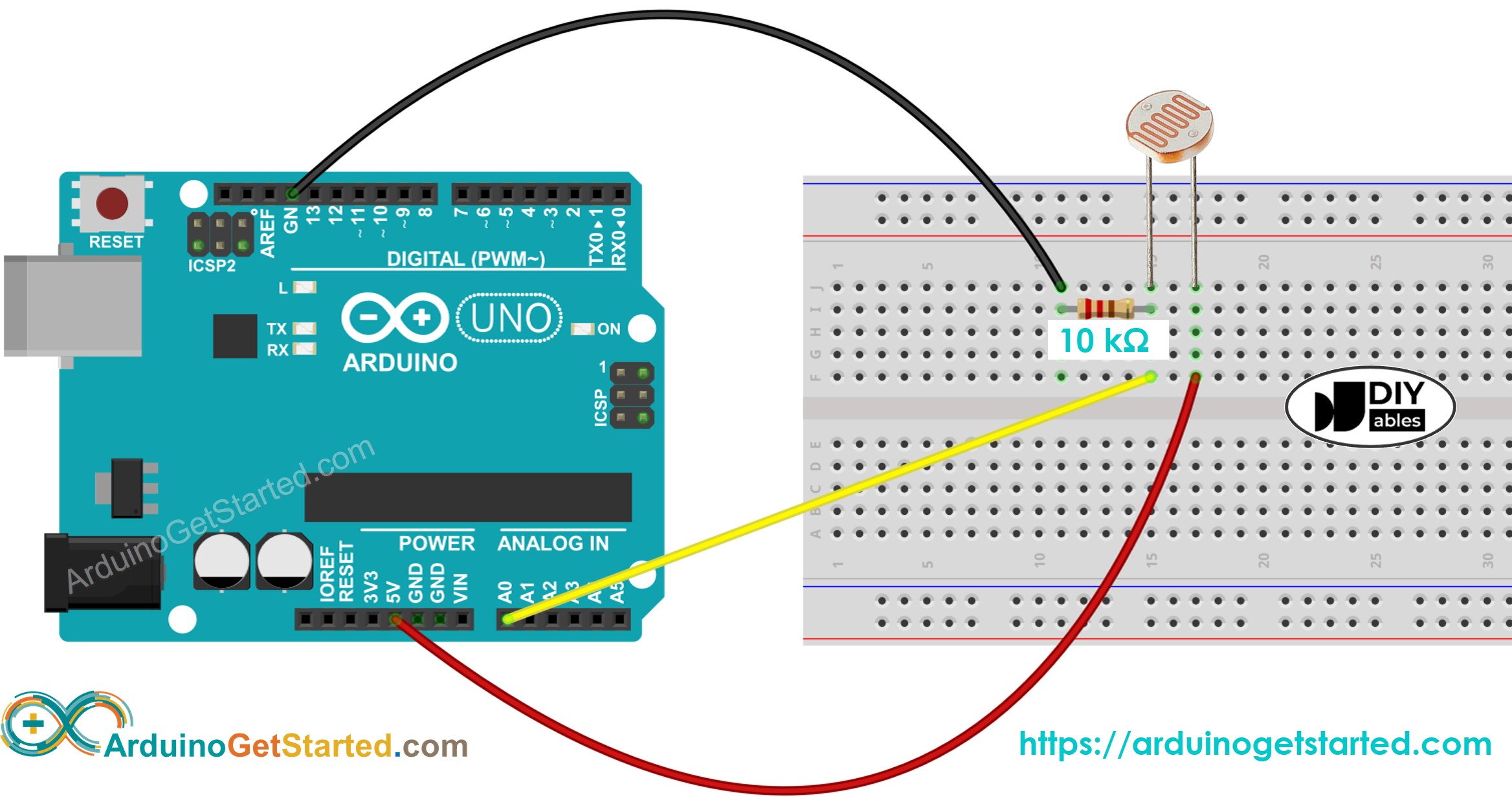
This image is created using Fritzing. Click to enlarge image
Arduino Code
The below code reads the value from photocell and determine the light level qualitatively
/*
 * Created by ArduinoGetStarted.com
 *
 * This example code is in the public domain
 *
 * Tutorial page: https://arduinogetstarted.com/tutorials/arduino-light-sensor
 */

void setup() {
  // initialize serial communication at 9600 bits per second:
  Serial.begin(9600);
}

void loop() {
  // reads the input on analog pin A0 (value between 0 and 1023)
  int analogValue = analogRead(A0);

  Serial.print("Analog reading: ");
  Serial.print(analogValue);   // the raw analog reading

  // We'll have a few threshholds, qualitatively determined
  if (analogValue < 10) {
    Serial.println(" - Dark");
  } else if (analogValue < 200) {
    Serial.println(" - Dim");
  } else if (analogValue < 500) {
    Serial.println(" - Light");
  } else if (analogValue < 800) {
    Serial.println(" - Bright");
  } else {
    Serial.println(" - Very bright");
  }

  delay(500);
}
Light Sensor and LED
-
The below code turns ON the LED when it is dark, otherwise turns OFF the LED
/*
- Created by ArduinoGetStarted.com
- This example code is in the public domain
- Tutorial page: https://arduinogetstarted.com/tutorials/arduino-light-sensor
*/
// constants won't change
const int LIGHT_SENSOR_PIN = A0; // Arduino pin connected to light sensor's pin
const int LED_PIN = 3; // Arduino pin connected to LED's pin
const int ANALOG_THRESHOLD = 500;// variables will change:
int analogValue;void setup() {
pinMode(LED_PIN, OUTPUT); // set arduino pin to output mode
}void loop() {
analogValue = analogRead(LIGHT_SENSOR_PIN); // read the input on analog pinif(analogValue < ANALOG_THRESHOLD) digitalWrite(LED_PIN, HIGH); // turn on LED else digitalWrite(LED_PIN, LOW); // turn off LED}
-
Wring diagram for the above code:
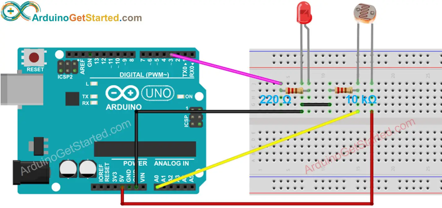
This image is created using Fritzing. Click to enlarge image
/*
 * Created by ArduinoGetStarted.com
 *
 * This example code is in the public domain
 *
 * Tutorial page: https://arduinogetstarted.com/tutorials/arduino-light-sensor
 */

void setup() {
  // initialize serial communication at 9600 bits per second:
  Serial.begin(9600);
}

void loop() {
  // reads the input on analog pin A0 (value between 0 and 1023)
  int analogValue = analogRead(A0);

  Serial.print("Analog reading: ");
  Serial.print(analogValue);   // the raw analog reading

  // We'll have a few threshholds, qualitatively determined
  if (analogValue < 10) {
    Serial.println(" - Dark");
  } else if (analogValue < 200) {
    Serial.println(" - Dim");
  } else if (analogValue < 500) {
    Serial.println(" - Light");
  } else if (analogValue < 800) {
    Serial.println(" - Bright");
  } else {
    Serial.println(" - Very bright");
  }

  delay(500);
}
Arduino - LDR模块
The LDR light sensor module is capable of detecting and measuring light in the surrounding environment. The module provides two outputs: a digital output (LOW/HIGH) and an analog output.
LDR光传感器模块能够检测和测量周围环境中的光。该模块提供两个输出:一个数字输出(LOW/HIGH)和一个模拟输出。
Arduino Uno R4 WiFi Led Matrix
Arduino Uno R4 WiFi LED 矩阵
In this tutorial, we will learn how to use an Arduino and an LDR light sensor module to detect and measure the light level. Specifically, we will cover the following:
在本教程中,我们将学习如何使用 Arduino 和 LDR 光传感器模块来检测和测量光照水平。具体而言,我们将涵盖以下内容:
- How to connect the LDR light sensor module to an Arduino.
如何将 LDR 光传感器模块连接到 Arduino。 - How to program the Arduino to detect light by reading the digital signal from the LDR light sensor module.
如何对Arduino进行编程,通过读取来自LDR光传感器模块的数字信号来检测光。 - How to program the Arduino to measure the light level by reading the analog signal from the LDR light sensor module.
如何对Arduino进行编程,通过读取来自LDR光传感器模块的模拟信号来测量光照水平。
Afterward, you can modify the code to activate an LED or a light bulb (via a relay) when it detects light.
之后,您可以修改代码以在检测到光时激活 LED 或灯泡(通过继电器)。
If you prefer a light sensor in its raw form, I suggest exploring the tutorial on the Arduino - Light Sensor.
如果您更喜欢原始形式的光传感器,我建议您浏览有关Arduino-光传感器的教程。
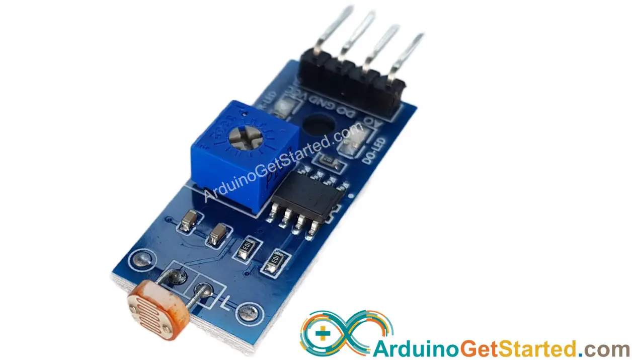
About LDR Light Sensor Module 关于LDR光传感器模块
The LDR light sensor module can be utilized to detect the presence of light or measure the light level in the surrounding environment. It provides two options via a digital output pin and analog output pin.
LDR光传感器模块可用于检测光的存在或测量周围环境中的光水平。它通过数字输出引脚和模拟输出引脚提供两种选择。
Pinout 引脚排列
The LDR light sensor module includes four pins:
LDR 光传感器模块包括四个引脚:
- VCC pin: It needs to be connected to VCC (3.3V to 5V).
VCC引脚:需要连接到VCC(3.3V至5V)。 - GND pin: It needs to be connected to GND (0V).
GND引脚:需要接GND(0V)。 - DO pin: It is a digital output pin. It is HIGH if it is dark and LOW if it is light. The threshold value between darkness and lightness can be adjusted using a built-in potentiometer.
DO引脚:它是数字输出引脚。如果它是黑暗的,它是高的,如果它是光明的,它是低的。可以使用内置电位器调整暗度和亮度之间的阈值。 - AO pin: It is an analog output pin. The output value decreases as the light gets brighter, and it increases as the light gets darker.
AO引脚:它是一个模拟输出引脚。输出值随着光线变亮而降低,随着光线变暗而增加。
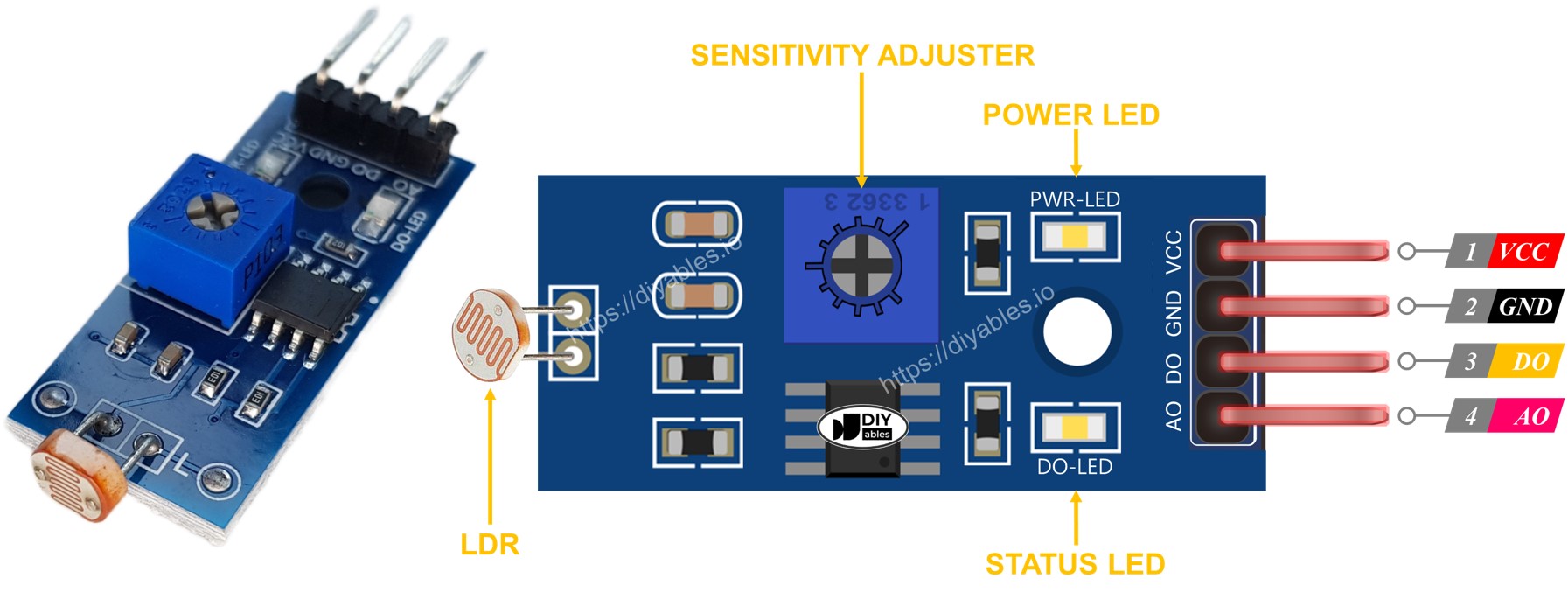
Furthermore, it has two LED indicators:
此外,它还有两个 LED 指示灯:
- One PWR-LED indicator for power.
一个 PWR-LED 电源指示灯。 - One DO-LED indicator for the light state on the DO pin: it is on when light is present and off when it is dark.
一个 DO-LED 指示灯用于指示 DO 引脚上的亮状态:有光时亮起,天暗时熄灭。
How It Works 它是如何工作的
For the DO pin:
对于 DO 引脚:
- The module has a built-in potentiometer for setting the light threshold (sensitivity).
该模块具有一个内置电位器,用于设置光阈值(灵敏度)。 - When the light intensity in the surrounding environment is above the threshold value (light), the output pin of the sensor is LOW , and the DO-LED is on.
当周围环境中的光强度高于阈值(光)时,传感器的输出引脚为低电平,DO-LED亮起。 - When the light intensity in the surrounding environment is below the threshold value (dark), the output pin of the sensor is HIGH , and the DO-LED is off.
当周围环境中的光强度低于阈值(暗)时,传感器的输出引脚为高电平,DO-LED 熄灭。
For the AO pin:
对于 AO 引脚:
- The higher the light intensity in the surrounding environment (light), the lower the value read from the AO pin.
周围环境(光)中的光强度越高,从AO引脚读取的值就越低。 - The lower the light intensity in the surrounding environment (dark), the higher the value read from the AO pin.
周围环境(黑暗)中的光强度越低,从AO引脚读取的值就越高。
Note that the potentiometer does not affect the value on the AO pin.
请注意,电位器不会影响 AO 引脚上的值。
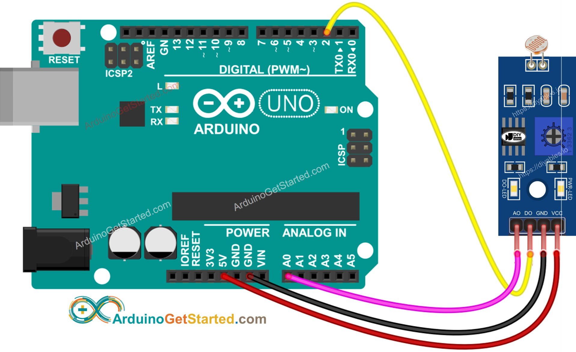
Wiring Diagram 接线图
Since the light sensor module has two outputs, you can choose to use one or both of them, depending on what you need.
由于光传感器模块有两个输出,您可以根据需要选择使用其中一个或两个输出。
- The wiring diagram between Arduino and the LDR light sensor module when using DO only.
仅使用 DO 时 Arduino 和 LDR 光传感器模块之间的接线图。
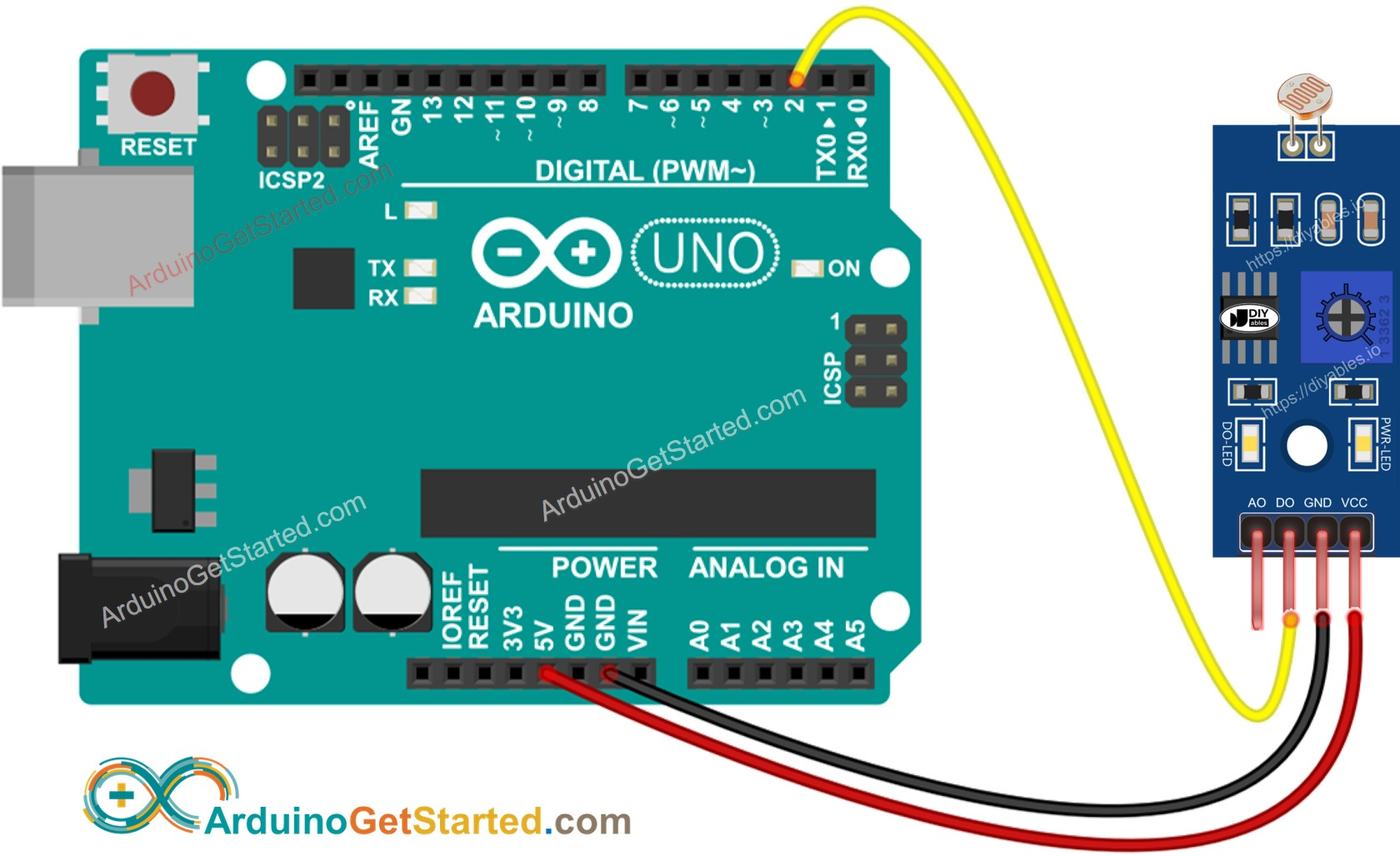
This image is created using Fritzing. Click to enlarge image
此图像是使用 Fritzing 创建的。点击放大图片
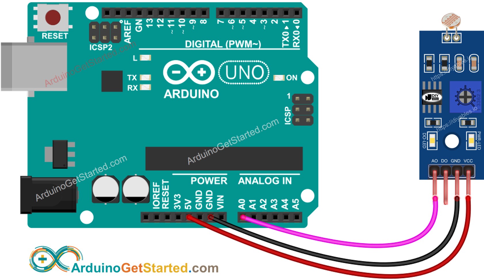
- The wiring diagram between Arduino and the LDR light sensor module when using AO only.
仅使用 AO 时 Arduino 和 LDR 光传感器模块之间的接线图。
- The wiring diagram between Arduino and the LDR light sensor module when using both AO an DO.
Arduino和LDR光传感器模块使用AO和DO时的接线图。
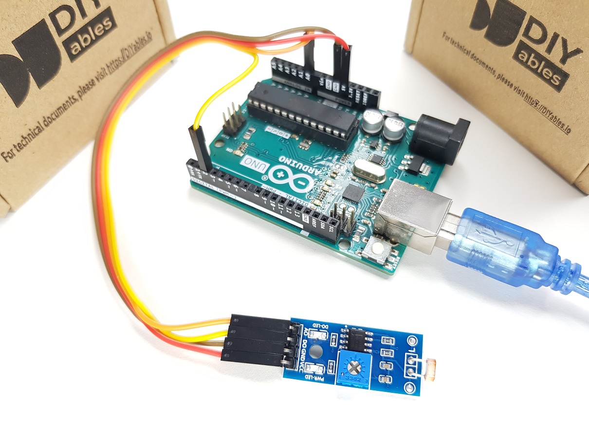
The real wiring: 真正的接线:
Arduino Code - Read value from DO pin Arduino 代码 - 从 DO 引脚读取值
/*

 * Created by ArduinoGetStarted.com
   *
 * This example code is in the public domain
   *
 * Tutorial page: https://arduinogetstarted.com/tutorials/arduino-ldr-module
   */

#define DO_PIN 2  // Arduino's pin connected to DO pin of the ldr module

void setup() {
  // initialize serial communication
  Serial.begin(9600);
  // initialize the Arduino's pin as an input
  pinMode(DO_PIN, INPUT);
}

void loop() {
  int lightState = digitalRead(DO_PIN);

  if (lightState == HIGH)
    Serial.println("The light is NOT present");
  else
    Serial.println("The light is present");
}
Quick Steps 快速步骤
- Copy the above code and open with Arduino IDE
复制上面的代码并使用Arduino IDE打开 - Click Upload button on Arduino IDE to upload code to Arduino
单击Arduino IDE上的"上传"按钮,将代码上传到Arduino - Cover and uncover the LDR light sensor module by your hand or something
用手或其他东西盖住并揭开 LDR 光传感器模块 - See the result on Serial Monitor.
在串行监视器上查看结果。
Please keep in mind that if you notice the LED status remaining on constantly or off even when there is light, you can adjust the potentiometer to fine-tune the light sensitivity of the sensor.
请记住,如果您发现 LED 状态即使在有光的情况下也保持亮起或熄灭,您可以调整电位器以微调传感器的感光度。
Now we can customize the code to activate an LED or a light when the light is detected, or even make a servo motor rotate. You can find more information and step-by-step instructions in the tutorials provided at the end of this tutorial.
现在我们可以自定义代码以在检测到光时激活 LED 或灯,甚至可以使伺服电机旋转。您可以在本教程末尾提供的教程中找到更多信息和分步说明。
Arduino Code - Read value from AO pin Arduino 代码 - 从 AO 引脚读取值
/*

 * Created by ArduinoGetStarted.com
   *
 * This example code is in the public domain
   *
 * Tutorial page: https://arduinogetstarted.com/tutorials/arduino-ldr-module
   */

#define AO_PIN A0  // Arduino's pin connected to AO pin of the ldr module

void setup() {
  // initialize serial communication
  Serial.begin(9600);
}

void loop() {
  int lightValue = analogRead(AO_PIN);

  Serial.println(lightValue);
}
Quick Steps 快速步骤
- Copy the above code and open with Arduino IDE
复制上面的代码并使用Arduino IDE打开 - Click Upload button on Arduino IDE to upload code to Arduino
单击Arduino IDE上的"上传"按钮,将代码上传到Arduino - Cover and uncover the LDR light sensor module by your hand or something
用手或其他东西盖住并揭开 LDR 光传感器模块 - See the result on Serial Monitor.
在串行监视器上查看结果。