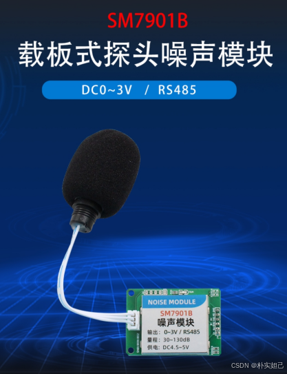
最近在做基于stm32的声音采集与频谱分析,试用了几款声音传感器,今天分享一款名为SM7901B的声音传感器数据采集代码,同样使用SM7901B的友友可以参考,求赞~比♥
这款声音传感器通过 RS485 MODBUS-RTU 数据通信
下面是数据手册

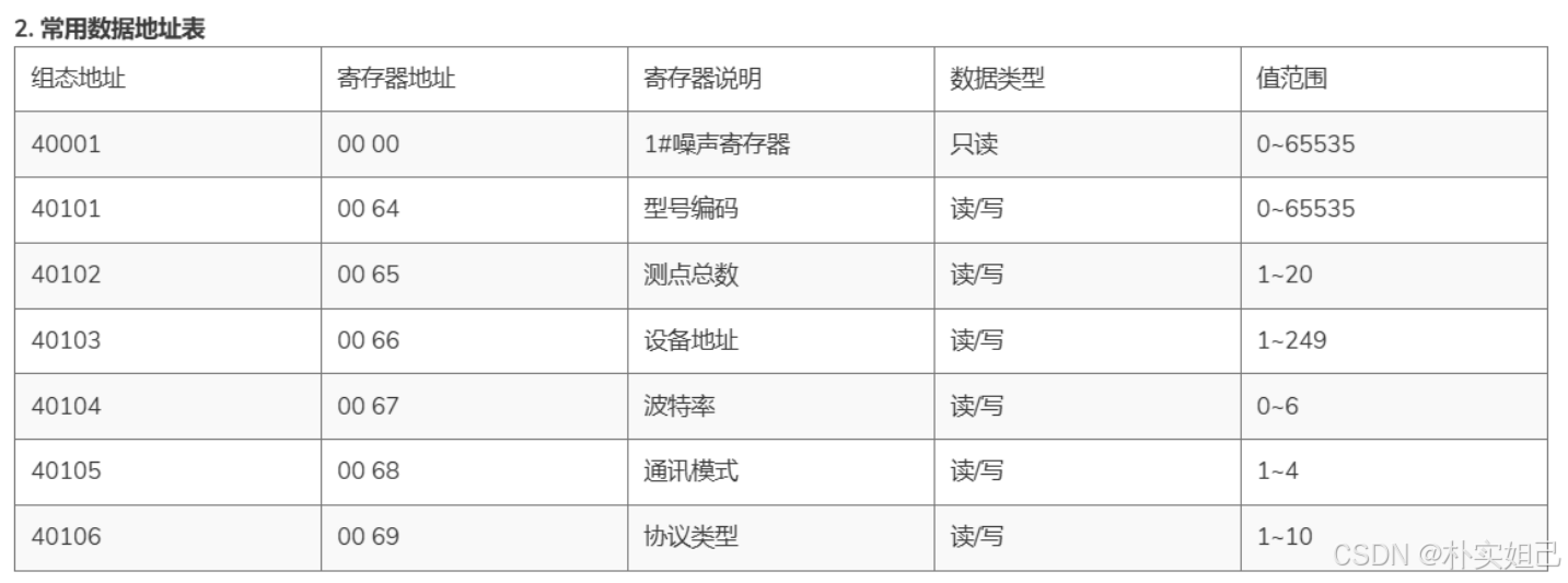
可以看出,串口应该给声音传感器发送
u8 hex_data[BUFFER_SIZE] = {0x01, 0x03, 0x00, 0x00, 0x00, 0x01, 0x84, 0x0A}; //需要发送的数据stm32每发送给声音传感器一条数据,声音传感器就发送给stm32一条数据,其中寄存器地址 0001,的2位16进制数据就是声音数据
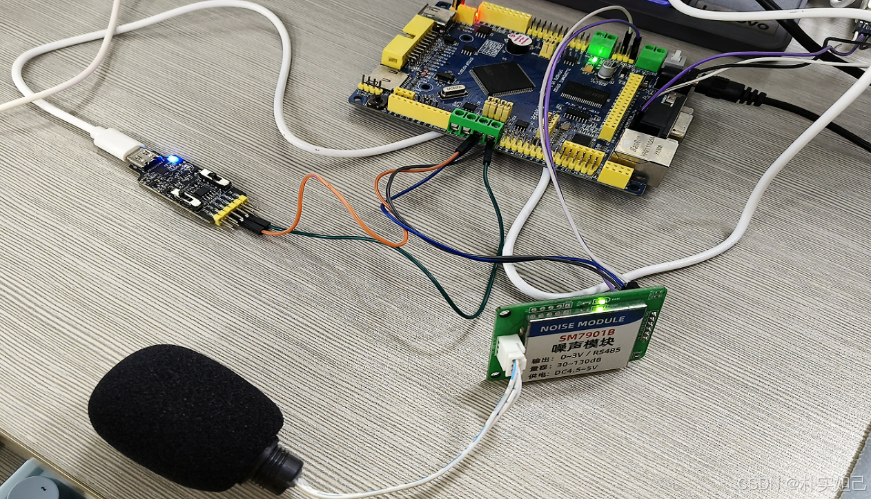
所以如果想只采集到寄存器地址 0001,的2位16进制数据,需要用到2个串口,一个串口需要连接串口-RS485模块,给声音传感器循环发送{0x01, 0x03, 0x00, 0x00, 0x00, 0x01, 0x84, 0x0A},我在这使用的是串口2
另一个串口(我使用的是串口1)需要把串口2接收的数据计数,只取寄存器地址 0001,的2位16进制数据,即声音数据,然后把16进制数据转换为十进制,发送到串口助手方便查看,下面上代码:
首先是串口2代码:
#include "uart2.h"
#include "string.h"
#include "stdlib.h"
#include "led.h"
#include "beep.h"
#include "uart1.h"
#include "stdio.h"
#include "stddef.h"
#include "string.h"


//接收缓存区
u8 RS485_receive_str[16];   //接收缓冲,最大128个字节.
u8 uart_byte_count2=0;        //接收到的数据长度

u8 byte4, byte5, byte6, byte7;

volatile u8 new_data_available = 0; //标志位 用来指示发送


//初始化IO 串口2   bound:波特率
void uart2_init(u32 bound)
{
  GPIO_InitTypeDef GPIO_InitStructure;
	USART_InitTypeDef USART_InitStructure;
	NVIC_InitTypeDef NVIC_InitStructure;

	RCC_AHB1PeriphClockCmd(RCC_AHB1Periph_GPIOA,ENABLE); //使能GPIOA时钟
	RCC_APB1PeriphClockCmd(RCC_APB1Periph_USART2,ENABLE);//使能USART2时钟

  //串口2引脚复用映射
	GPIO_PinAFConfig(GPIOA,GPIO_PinSource2,GPIO_AF_USART2); //GPIOA2复用为USART2
	GPIO_PinAFConfig(GPIOA,GPIO_PinSource3,GPIO_AF_USART2); //GPIOA3复用为USART2

	//USART2
  GPIO_InitStructure.GPIO_Pin = GPIO_Pin_2 | GPIO_Pin_3; //GPIOA2与GPIOA3
	GPIO_InitStructure.GPIO_Mode = GPIO_Mode_AF;//复用功能
	GPIO_InitStructure.GPIO_Speed = GPIO_Speed_100MHz;	//速度100MHz
	GPIO_InitStructure.GPIO_OType = GPIO_OType_PP; //推挽复用输出
	GPIO_InitStructure.GPIO_PuPd = GPIO_PuPd_UP; //上拉
	GPIO_Init(GPIOA,&GPIO_InitStructure); //初始化PA2,PA3

	//PG8推挽输出,485模式控制
  GPIO_InitStructure.GPIO_Pin = GPIO_Pin_6; //GPIOG6
	GPIO_InitStructure.GPIO_Mode = GPIO_Mode_OUT;//输出
	GPIO_InitStructure.GPIO_Speed = GPIO_Speed_100MHz;	//速度100MHz
	GPIO_InitStructure.GPIO_OType = GPIO_OType_PP; //推挽输出
	GPIO_InitStructure.GPIO_PuPd = GPIO_PuPd_UP; //上拉
	GPIO_Init(GPIOG,&GPIO_InitStructure); //初始化PG8

	RS485_TX_EN=0;				//初始化默认为接收模式

   //USART2 初始化设置
	USART_InitStructure.USART_BaudRate = bound;//波特率设置
	USART_InitStructure.USART_WordLength = USART_WordLength_8b;//字长为8位数据格式
	USART_InitStructure.USART_StopBits = USART_StopBits_1;//一个停止位
	USART_InitStructure.USART_Parity = USART_Parity_No;//无奇偶校验位
	USART_InitStructure.USART_HardwareFlowControl = USART_HardwareFlowControl_None;//无硬件数据流控制
	USART_InitStructure.USART_Mode = USART_Mode_Rx | USART_Mode_Tx;	//收发模式
  USART_Init(USART2, &USART_InitStructure); //初始化串口2

  USART_Cmd(USART2, ENABLE);  //使能串口 2
	USART_ClearFlag(USART2, USART_FLAG_TC);
	USART_ITConfig(USART2, USART_IT_RXNE, ENABLE);//开启接受中断

	//Usart2 NVIC 配置
  NVIC_InitStructure.NVIC_IRQChannel = USART2_IRQn;
	NVIC_InitStructure.NVIC_IRQChannelPreemptionPriority=3;//抢占优先级3
	NVIC_InitStructure.NVIC_IRQChannelSubPriority =3;		//子优先级3
	NVIC_InitStructure.NVIC_IRQChannelCmd = ENABLE;			//IRQ通道使能
	NVIC_Init(&NVIC_InitStructure);	//根据指定的参数初始化VIC寄存器、
}

//串口2接收中断服务函数
void USART2_IRQHandler(void)
{
	u8 rec_data;
	RS485_TX_EN=0;				//初始化默认为接收模式


	if(USART_GetITStatus(USART2, USART_IT_RXNE) != RESET)//接收到数据
	{
		USART_ClearITPendingBit(USART2, USART_IT_RXNE);
		rec_data =(u8)USART_ReceiveData(USART2);         //(USART2->DR) 读取接收到的数据
		uart_byte_count2++;
		RS485_receive_str[uart_byte_count2-1] = rec_data;

	 if(uart_byte_count2>=16)
	{
		 byte4 = RS485_receive_str[10];
     byte5 = RS485_receive_str[11];
     byte6 = RS485_receive_str[12];
     byte7 = RS485_receive_str[13];

     new_data_available = 1; //标志位=1 有数据要发送

     if(new_data_available == 0){

			 memset(RS485_receive_str, 0x00, sizeof(RS485_receive_str));//串口2数组清零
			 uart_byte_count2 = 0;//计数器归零
			}


		 }

	}

}

//串口2的发送

void RS485_Send_Data(u8 *buf,u8 len)
{
	u8 t;
	RS485_TX_EN=1;			    //设置为发送模式
  	for(t=0;t<len;t++)		//循环发送数据
	{
	  while(USART_GetFlagStatus(USART2,USART_FLAG_TC)==RESET); //等待发送结束
    USART_SendData(USART2,buf[t]); //发送数据
		LED0=0;
	}
	while(USART_GetFlagStatus(USART2,USART_FLAG_TC)==RESET);   //等待发送结束

	RS485_TX_EN=0;				//发送完设置为接收模式
	LED0 = (LED0 == 0) ? 1 : 0;//发完闪烁一下
}
我上面的代码接收了4位,其实只需要用到两位
然后是串口1代码:
#include "uart1.h"
#include "string.h"
#include "stdlib.h"
#include "led.h"
#include "uart2.h"
#include "stdio.h"
#include "stddef.h"
#include "string.h"


u8 receive_str[4];     //接收缓存数组,最大USART_REC_LEN个字节
u8 uart_byte_count1=0;


void uart1_init(u32 bound)
{   //GPIO端口设置
  GPIO_InitTypeDef GPIO_InitStructure;
	USART_InitTypeDef USART_InitStructure;
	NVIC_InitTypeDef NVIC_InitStructure;

	RCC_AHB1PeriphClockCmd(RCC_AHB1Periph_GPIOA,ENABLE); //使能GPIOA时钟
	RCC_APB2PeriphClockCmd(RCC_APB2Periph_USART1,ENABLE);//使能USART1时钟
	//串口1对应引脚复用映射
	GPIO_PinAFConfig(GPIOA,GPIO_PinSource9,GPIO_AF_USART1);  //GPIOA9复用为USART1
	GPIO_PinAFConfig(GPIOA,GPIO_PinSource10,GPIO_AF_USART1); //GPIOA10复用为USART1
	//USART1端口配置
  GPIO_InitStructure.GPIO_Pin = GPIO_Pin_9 | GPIO_Pin_10; //GPIOA9与GPIOA10
	GPIO_InitStructure.GPIO_Mode = GPIO_Mode_AF;      //复用功能
	GPIO_InitStructure.GPIO_Speed = GPIO_Speed_50MHz;	//速度50MHz
	GPIO_InitStructure.GPIO_OType = GPIO_OType_PP; //推挽复用输出
	GPIO_InitStructure.GPIO_PuPd = GPIO_PuPd_UP;   //上拉
	GPIO_Init(GPIOA,&GPIO_InitStructure);          //初始化PA9,PA10
   //USART1 初始化设置
	USART_InitStructure.USART_BaudRate = bound;//波特率设置
	USART_InitStructure.USART_WordLength = USART_WordLength_8b;//字长为8位数据格式
	USART_InitStructure.USART_StopBits = USART_StopBits_1;  //一个停止位
	USART_InitStructure.USART_Parity = USART_Parity_No;//无奇偶校验位
	USART_InitStructure.USART_HardwareFlowControl = USART_HardwareFlowControl_None;//无硬件数据流控制
	USART_InitStructure.USART_Mode = USART_Mode_Rx | USART_Mode_Tx;	//收发模式
  USART_Init(USART1, &USART_InitStructure); //初始化串口1
  USART_Cmd(USART1, ENABLE);  //使能串口1

	USART_ClearFlag(USART1, USART_FLAG_TC);

	USART_ITConfig(USART1, USART_IT_RXNE, ENABLE);         //开启相关中断
	//Usart1 NVIC 配置
  NVIC_InitStructure.NVIC_IRQChannel = USART1_IRQn;      //串口1中断通道
	NVIC_InitStructure.NVIC_IRQChannelPreemptionPriority=3;//抢占优先级3
	NVIC_InitStructure.NVIC_IRQChannelSubPriority =3;		   //子优先级3
	NVIC_InitStructure.NVIC_IRQChannelCmd = ENABLE;			   //IRQ通道使能
	NVIC_Init(&NVIC_InitStructure);	  //根据指定的参数初始化VIC寄存器、
}

//串口1中断服务程序
void USART1_IRQHandler(void)
{
	u8 rec_data;
	if(USART_GetITStatus(USART1, USART_IT_RXNE) != RESET)  //接收中断
		{
				rec_data =(u8)USART_ReceiveData(USART1);         //(USART1->DR) 读取接收到的数据

			 if((uart_byte_count1>0)&&(uart_byte_count1<=512))
				{
				   receive_str[uart_byte_count1-1]=rec_data;
				   uart_byte_count1++;
				}
   }
}

//串口1发送

void uart1_send_num (u8 *buf,u8 len)
{
	u8 i;
  	for(i=0;i<len;i++)		//循环发送数据
	{
	  while(USART_GetFlagStatus(USART1,USART_FLAG_TC)==RESET); //等待发送结束
    USART_SendData(USART1,buf[i]); //发送数据
		LED2 = (LED2 == 0) ? 1 : 0;//发完闪烁一下
	}
	while(USART_GetFlagStatus(USART1,USART_FLAG_TC)==RESET);   //等待发送结束

}
最后是main代码:
#include "led.h"
#include "beep.h"
#include "lcd.h"
#include "key.h"
#include "uart1.h"
#include "uart2.h"
#include "stdio.h"
#include "stddef.h"
#include "string.h"
#define BUFFER_SIZE 8 // 发送的数据长度
u8 hex_data[BUFFER_SIZE] = {0x01, 0x03, 0x00, 0x00, 0x00, 0x01, 0x84, 0x0A}; //需要发送的数据
u8 data[4];
u8 i;
u16 x_data;
u16 y_data;
s16 x_signed;
s16 y_signed;
float value;
char send_buffer[50];
char send_alarm[10];
int main(void)
{
NVIC_PriorityGroupConfig(NVIC_PriorityGroup_2);//设置系统中断优先级分组2
delay_init(); //初始化延时函数
LED_Init(); //初始化LED
BEEP_Init(); //初始化蜂鸣器
LCD_Init(); //LCD初始化
KEY_Init(); //按键初始化
LED1=0;
uart2_init(115200);//
uart1_init(115200);//
while(1)
{
RS485_Send_Data(hex_data, BUFFER_SIZE);//串口2发送
delay_ms(100);
if (new_data_available == 1)
{
data[0]=byte4;
data[1]=byte5;
x_data = ((u16)byte4 << 8) | byte5;//拼接
x_signed = 0;
if ((byte4 & 0x80) != 0) // 处理x轴
{
x_data = (~x_data) + 1; //
x_signed = -x_data;
}
else
{
x_signed = x_data;
}
//负数
if (x_signed > 60000)
{
x_signed -= 65536;
}
value = (float)x_signed / 10.0;
snprintf(send_buffer, sizeof(send_buffer), "channel:%.2f,\n", value);
uart1_send_num((u8 *)send_buffer, strlen(send_buffer));//串口1发送dB
//uart1_send_num(data, 2);//串口1发送
new_data_available = 0;
memset(RS485_receive_str, 0x00, sizeof(RS485_receive_str));
uart_byte_count2 = 0;
delay_ms(100);
}
}
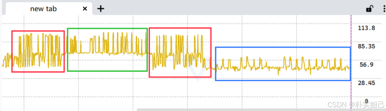
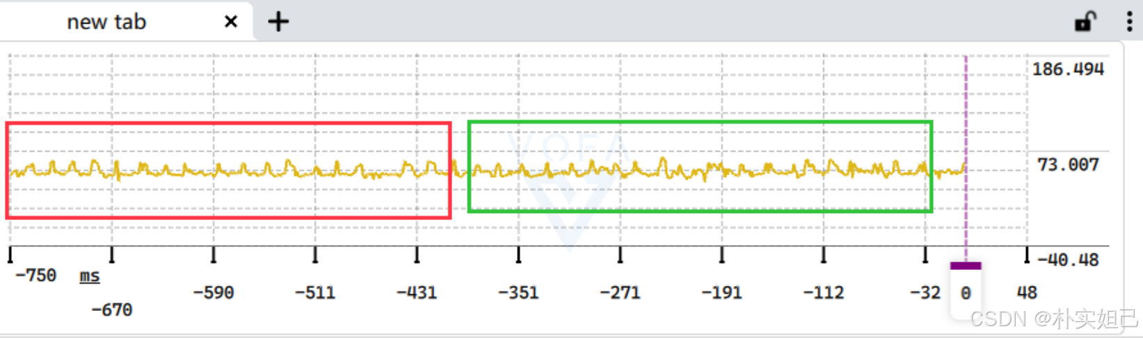
}完整代码我上传到资源,下面分享一下测试结果,个人感觉这款传感器测试的结果我感觉很一般。
开始测试,红色为环境音,绿色是敲击桌面,区别不大
查找后,是声音采集传感器的收音口覆盖的黑色收音布隔绝了声音,把收音口黑布撕开
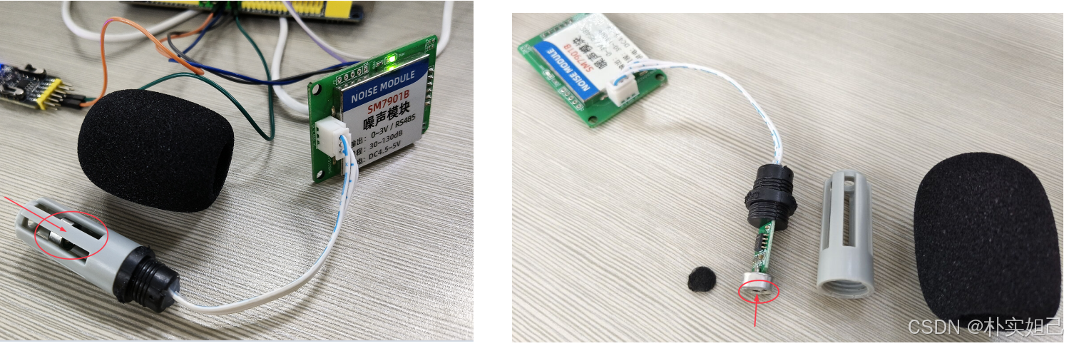
对着收音口输出音频
红色为一种音频,绿色为一种音频信号,蓝色是无音频输出时的信号,这样才有较大区别