版本:Vivado2020.2(Vitis)
任务:以 VDAM IP 为核心实现 VGA 彩条图像显示,同时支持输出分辨率可调。
(PS 端写入彩条数据到 DDR 通过 VDMA 读取出来输出给 VGA 进行显示)
目录
[(2)VTC 配置](#(2)VTC 配置)
[(3)Clock 时钟配置](#(3)Clock 时钟配置)
一、介绍
本例基于上次例程进行优化,实现 VGA 彩条图像显示的同时,支持输出分辨率可调,以满足不同视频分辨率的需求。
参考了正点原子的例程,但有所不同,他是通过 AXI GPIO 读取 LCD设备型号 ID 判断并配置分辨率。而我使用 VGA 进行显示且大多数 VGA 显示器都支持多种分辨率输入,对于不同型号 VGA 显示器各有差别,所以就直接通过PS端主动调节输出分辨率即可。本次只设计三种 VGA 分辨率可调:640*480@60Hz、800x600@60Hz、1280*720@60Hz。
二、硬件设计
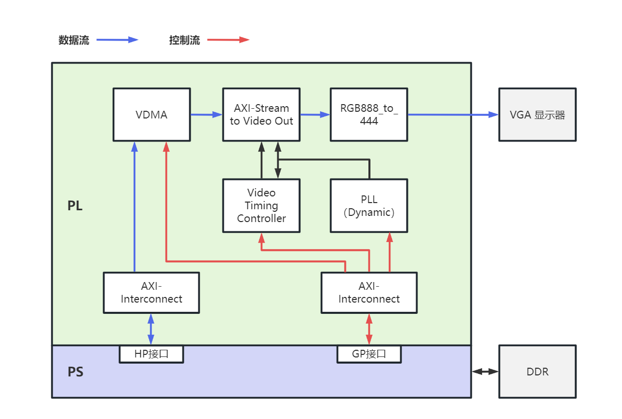
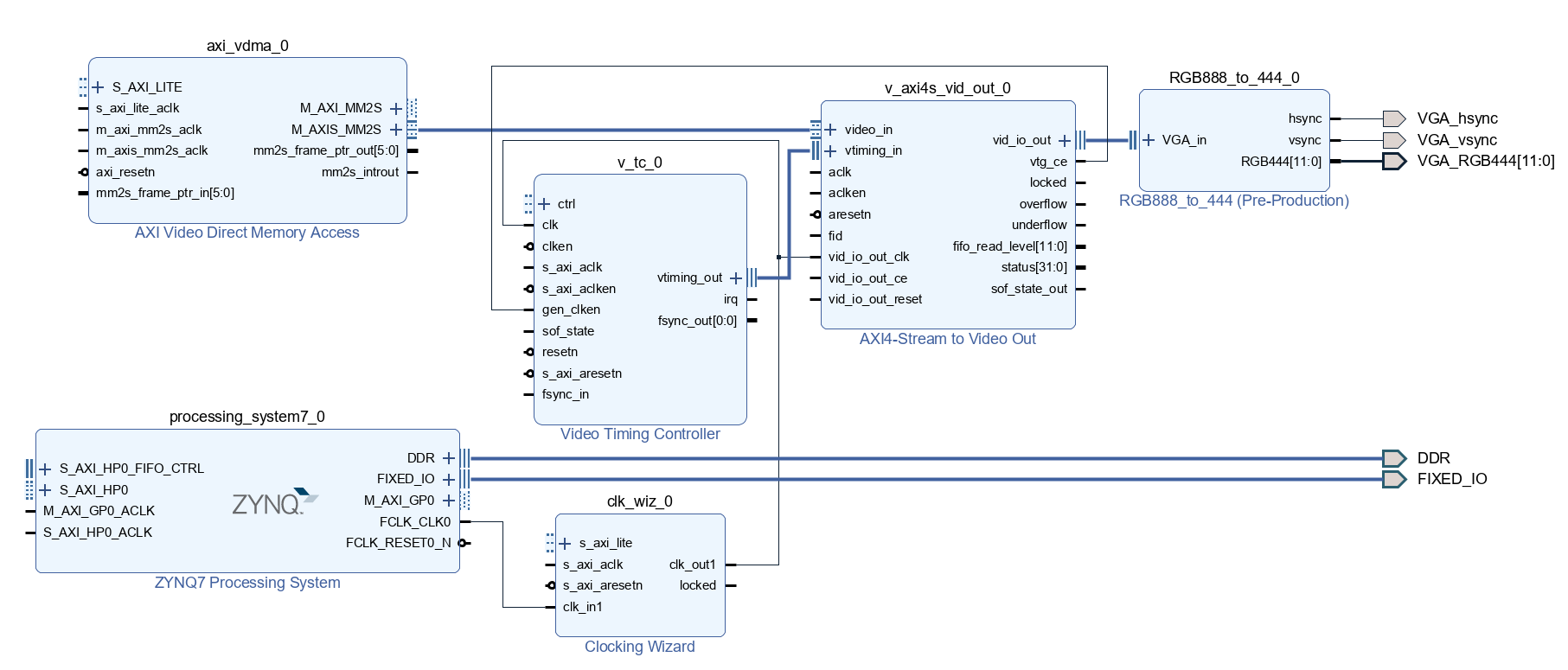
(1)整体系统框架
框架和 "笔记十八"里面一致,区别在于时钟IP配置为可动态调节,PS端通过 GP 接口可对其输出时钟进行配置,此外还将 RGB888_to_444 模块进行优化并封装为带 vid_io_rtl 类型接口输入的 IP核,使BD设计视图更加简洁清晰。
基本原理、相关 IP 介绍、系统框架搭建参考:ZYNQ笔记(十八):VDMA VGA彩条显示
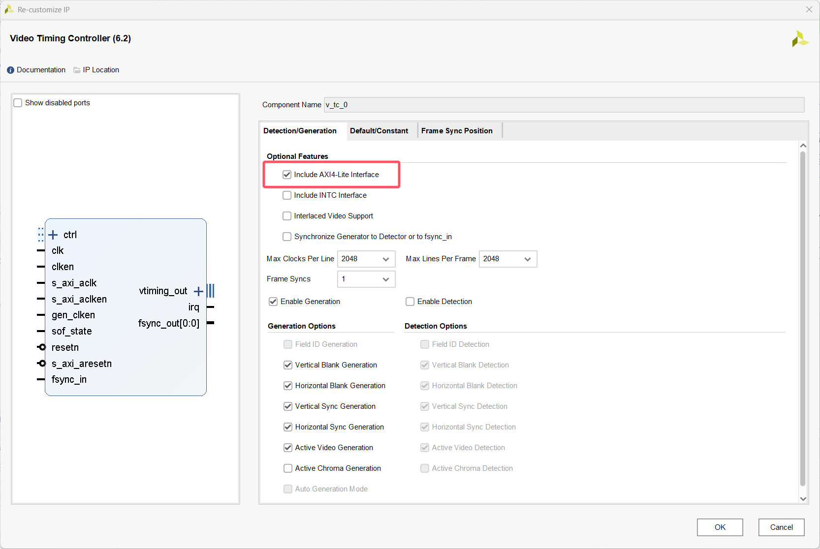
(2)VTC 配置
在之前配置的基础上添加 AXI-Lite 接口,这样 PS 端可以通过 GP 接口对其进行配置
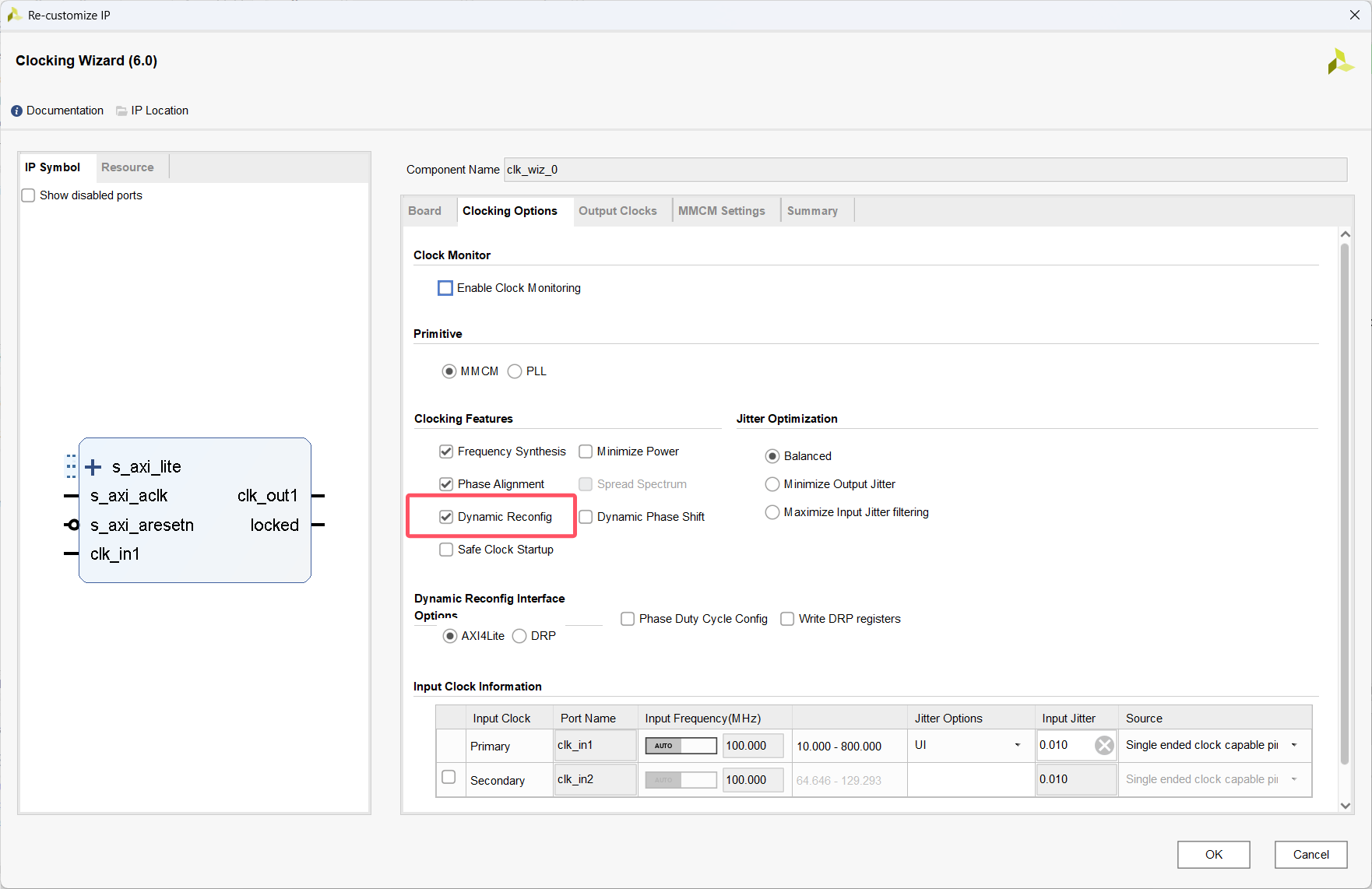
(3)Clock 时钟配置
不同分辨率像素时钟不同,所以需要对应输出不同频率的时钟,Clock IP 启用动态配置功能,可以看到 IP 增加了一组 AXI-Lite 接口。这样 PS 端可以通过 GP 接口对其输出时钟频率进行重新配置。
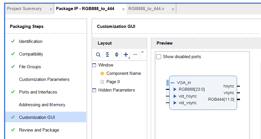
(4)RGB888_to_444
之前的 RGB888_to_444 是作为模块添加到 bd设计中,将Video Out 输出的 RGB888 数据进行截位与拼接,输出 RGB444 格式数据。为了让 bd 设计更加简洁规范,把它封装为有关带 vid_io_rtl 类型接口输入的 IP 核,以连接 Video Out IP 的视频信号接口。
cs
`timescale 1ns / 1ps
module RGB888_to_444(
    input  wire         vid_hsync,  //  输入行同步信号
    input  wire         vid_vsync,  //  输入场同步信号
    input  wire [23:0]  RGB888,     //  24位RGB888输入 (R[23:16], G[15:8], B[7:0])
    output wire         hsync,      //  输出行同步信号
    output wire         vsync,      //  输出场同步信号
    output wire [11:0]  RGB444      //  12位RGB444输出 (R[11:8], G[7:4], B[3:0])
);
    assign vsync    =   vid_vsync;
    assign hsync    =   vid_hsync;
    assign RGB444   =   {RGB888[23:20], RGB888[15:12], RGB888[7:4]}; // 截取RGB888各通道的高4位,组合成RGB444
endmodule
IP 封装以及接口定义参考:ZYNQ笔记(十七):IP核封装与接口定义
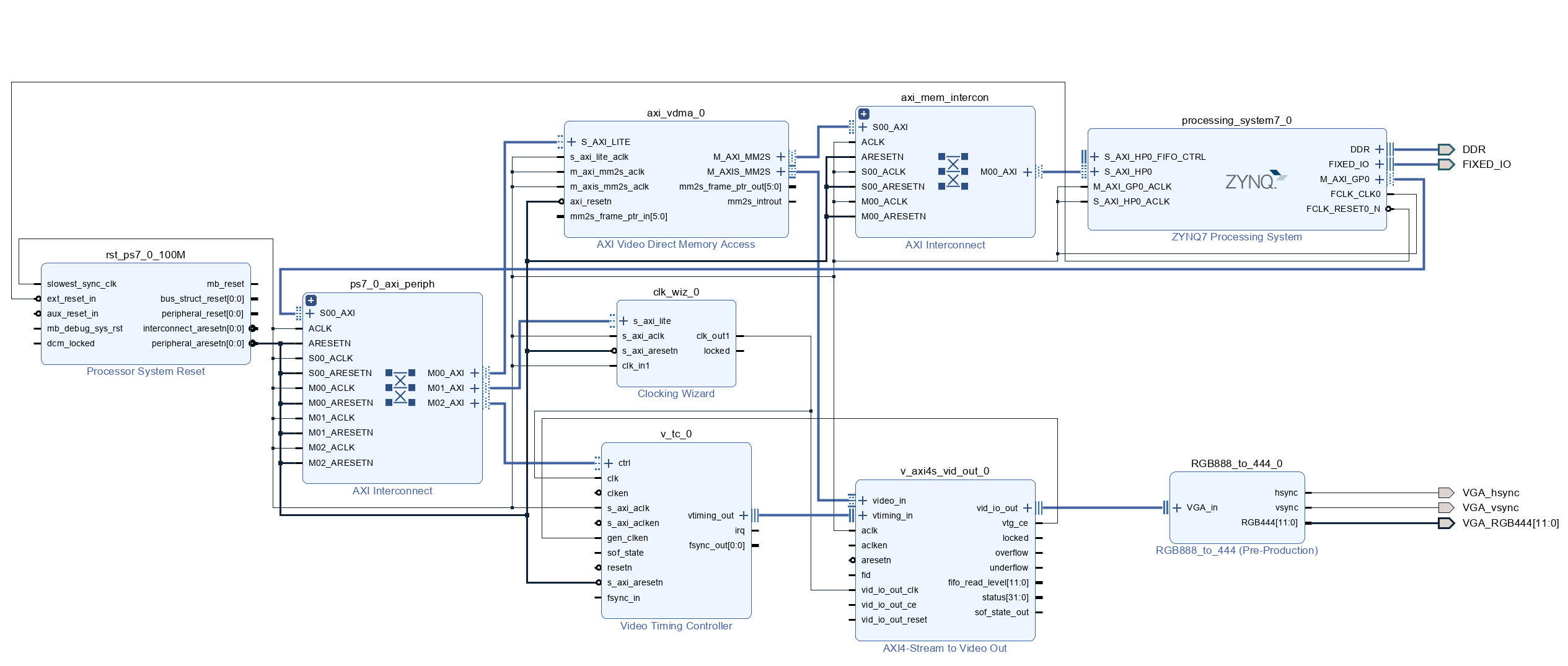
(5)连线
完成关键信号连线,连线情况如图所示:
再运行自动连接,最后整体 bd 设计部分如图所示:设计检查、Generate Output Products、 Create HDL Wrapper、管脚约束、Gnerate Bitstream、Export Hardware(包含比特流文件)、启动Vitis
三、软件设计
(1)clk_wiz
"xclk_wiz.h" 是Vitis提供的关于时钟IP核相关的库函数头文,"clk_wiz.h" 是自己编写的用于定义时钟相关寄存器的头文件。
clk_wiz.h :
cs
#ifndef CLK_WIZ_H_
#define CLK_WIZ_H_

#include "xil_types.h"

#define CLK_SR_OFFSET    0x04    //Status Register
#define CLK_CFG0_OFFSET  0x200   //Clock Configuration Register 0
#define CLK_CFG2_OFFSET  0x208   //Clock Configuration Register 2
#define CLK_CFG23_OFFSET 0x25C   //Clock Configuration Register 23

void clk_wiz_cfg(u32 clk_device_id,double freq);

#endif /* CLK_WIZ_H_ */
clk_wiz.c :
cs
#include "xclk_wiz.h"
#include "clk_wiz.h"
#include "xparameters.h"

#define CLK_WIZ_IN_FREQ 100  //时钟IP核输入100Mhz

XClk_Wiz clk_wiz_inst;       //时钟IP核驱动实例

//时钟IP核动态重配置
//参数1:时钟IP核的器件ID
//参数2:时钟IP核输出的时钟 单位:MHz
void clk_wiz_cfg(u32 clk_device_id,double freq)
{
	double div_factor = 0;
	u32 div_factor_int = 0,dviv_factor_frac=0;
	u32 clk_divide = 0;
	u32 status = 0;

	//初始化XCLK_Wiz
	XClk_Wiz_Config *clk_cfg_ptr;
	clk_cfg_ptr = XClk_Wiz_LookupConfig(clk_device_id);
	XClk_Wiz_CfgInitialize(&clk_wiz_inst,clk_cfg_ptr,clk_cfg_ptr->BaseAddr);

	if(freq <= 0)
		return;
	//配置时钟倍频/分频系数
	XClk_Wiz_WriteReg(clk_cfg_ptr->BaseAddr,CLK_CFG0_OFFSET,0x00000a01);  //10倍频,1分频
	//计算分频系数
	div_factor = CLK_WIZ_IN_FREQ * 10 / freq;
	div_factor_int = (u32)div_factor;
	dviv_factor_frac = (u32)((div_factor - div_factor_int) * 1000);
	clk_divide = div_factor_int | (dviv_factor_frac<<8);
	//配置分频系数
	XClk_Wiz_WriteReg(clk_cfg_ptr->BaseAddr,CLK_CFG2_OFFSET,clk_divide);
	//加载重配置的参数
	XClk_Wiz_WriteReg(clk_cfg_ptr->BaseAddr,CLK_CFG23_OFFSET,0x00000003);
	//获取时钟IP核的状态,判断是否重配置完成
	while(1){
		status = XClk_Wiz_ReadReg(clk_cfg_ptr->BaseAddr,CLK_SR_OFFSET);
		if(status&0x00000001)    //Bit0 Locked信号
			return ;
	}
}
(2)display_ctrl
这一部分使用的正点原子的代码,display_ctrl.c 和.h 是用于实现 VTC 配置的,不过做了一些微调(本例没用到GPIO)。同时还有一个 lcd_modes.h 包含不同分辨率格式的时序配置参数,同样适用于 VGA 显示器。代码如下:
display_ctrl.c
cs
/************************************************************************/
/*																		*/
/*	display_ctrl.c	--	Digilent Display Controller Driver				*/
/*																		*/
/************************************************************************/
/*	Author: Sam Bobrowicz												*/
/*	Copyright 2014, Digilent Inc.										*/
/************************************************************************/
/*  Module Description: 												*/
/*																		*/
/*		This module provides an easy to use API for controlling a    	*/
/*		Display attached to a Digilent system board via VGA or HDMI. 	*/
/*		run-time resolution setting and seamless framebuffer-swapping 	*/
/*		for tear-free animation. 										*/
/*																		*/
/*		To use this driver, you must have a Xilinx Video Timing 		*/
/* 		Controller core (vtc), Xilinx axi_vdma core, a Digilent 		*/
/*		axi_dynclk core, a Xilinx AXI Stream to Video core, and either  */
/*		a Digilent RGB2VGA or RGB2DVI core all present in your design.  */
/*		See the Video in or Display out reference projects for your     */
/*		system board to see how they need to be connected. Digilent     */
/*		reference projects and IP cores can be found at 				*/
/*		www.github.com/Digilent.			 							*/
/*																		*/
/*		The following steps should be followed to use this driver:		*/
/*		1) Create a DisplayCtrl object and pass a pointer to it to 		*/
/*		   DisplayInitialize.											*/
/*		2) Call DisplaySetMode to set the desired mode					*/
/*		3) Call DisplayStart to begin outputting data to the display	*/
/*		4) To create a seamless animation, draw the next image to a		*/
/*		   framebuffer currently not being displayed. Then call 		*/
/*		   DisplayChangeFrame to begin displaying that frame.			*/
/*		   Repeat as needed, only ever modifying inactive frames.		*/
/*		5) To change the resolution, call DisplaySetMode, followed by	*/
/*		   DisplayStart again.											*/
/*																		*/
/*																		*/
/************************************************************************/
/*  Revision History:													*/
/* 																		*/
/*		2/20/2014(SamB): Created										*/
/*		11/25/2015(SamB): Changed from axi_dispctrl to Xilinx cores		*/
/*						  Separated Clock functions into dynclk library */
/*																		*/
/************************************************************************/
/*
 * TODO: It would be nice to remove the need for users above this to access
 *       members of the DisplayCtrl struct manually. This can be done by
 *       implementing get/set functions for things like video mode, state,
 *       etc.
 */


/* ------------------------------------------------------------ */
/*				Include File Definitions						*/
/* ------------------------------------------------------------ */

/*
 * Uncomment for Debugging messages over UART
 */
//#define DEBUG

#include "display_ctrl.h"
#include "xdebug.h"
#include "xil_io.h"

/* ------------------------------------------------------------ */
/*				Procedure Definitions							*/
/* ------------------------------------------------------------ */

/***	DisplayStop(DisplayCtrl *dispPtr)
**
**	Parameters:
**		dispPtr - Pointer to the initialized DisplayCtrl struct
**
**	Return Value: int
**		XST_SUCCESS if successful.
**		XST_DMA_ERROR if an error was detected on the DMA channel. The
**			Display is still successfully stopped, and the error is
**			cleared so that subsequent DisplayStart calls will be
**			successful. This typically indicates insufficient bandwidth
**			on the AXI Memory-Map Interconnect (VDMA<->DDR)
**
**	Description:
**		Halts output to the display
**
*/
int DisplayStop(DisplayCtrl *dispPtr)
{
	/*
	 * If already stopped, do nothing
	 */
	if (dispPtr->state == DISPLAY_STOPPED)
	{
		return XST_SUCCESS;
	}

	/*
	 * Disable the disp_ctrl core, and wait for the current frame to finish (the core cannot stop
	 * mid-frame)
	 */
	XVtc_DisableGenerator(&dispPtr->vtc);

	/*
	 * Update Struct state
	 */
	dispPtr->state = DISPLAY_STOPPED;

	//TODO: consider stopping the clock here, perhaps after a check to see if the VTC is finished

	return XST_SUCCESS;
}
/* ------------------------------------------------------------ */

/***	DisplayStart(DisplayCtrl *dispPtr)
**
**	Parameters:
**		dispPtr - Pointer to the initialized DisplayCtrl struct
**
**	Return Value: int
**		XST_SUCCESS if successful, XST_FAILURE otherwise
**
**	Errors:
**
**	Description:
**		Starts the display.
**
*/
int DisplayStart(DisplayCtrl *dispPtr)
{
	XVtc_Timing vtcTiming;
	XVtc_SourceSelect SourceSelect;

	xdbg_printf(XDBG_DEBUG_GENERAL, "display start entered\n\r");
	/*
	 * If already started, do nothing
	 */
	if (dispPtr->state == DISPLAY_RUNNING)
	{
		return XST_SUCCESS;
	}

	/*
	 * Configure the vtc core with the display mode timing parameters
	 */
	vtcTiming.HActiveVideo = dispPtr->vMode.width;	/**< Horizontal Active Video Size */
	vtcTiming.HFrontPorch = dispPtr->vMode.hps - dispPtr->vMode.width;	/**< Horizontal Front Porch Size */
	vtcTiming.HSyncWidth = dispPtr->vMode.hpe - dispPtr->vMode.hps;		/**< Horizontal Sync Width */
	vtcTiming.HBackPorch = dispPtr->vMode.hmax - dispPtr->vMode.hpe + 1;		/**< Horizontal Back Porch Size */
	vtcTiming.HSyncPolarity = dispPtr->vMode.hpol;	/**< Horizontal Sync Polarity */
	vtcTiming.VActiveVideo = dispPtr->vMode.height;	/**< Vertical Active Video Size */
	vtcTiming.V0FrontPorch = dispPtr->vMode.vps - dispPtr->vMode.height;	/**< Vertical Front Porch Size */
	vtcTiming.V0SyncWidth = dispPtr->vMode.vpe - dispPtr->vMode.vps;	/**< Vertical Sync Width */
	vtcTiming.V0BackPorch = dispPtr->vMode.vmax - dispPtr->vMode.vpe + 1;;	/**< Horizontal Back Porch Size */
	vtcTiming.V1FrontPorch = dispPtr->vMode.vps - dispPtr->vMode.height;	/**< Vertical Front Porch Size */
	vtcTiming.V1SyncWidth = dispPtr->vMode.vpe - dispPtr->vMode.vps;	/**< Vertical Sync Width */
	vtcTiming.V1BackPorch = dispPtr->vMode.vmax - dispPtr->vMode.vpe + 1;;	/**< Horizontal Back Porch Size */
	vtcTiming.VSyncPolarity = dispPtr->vMode.vpol;	/**< Vertical Sync Polarity */
	vtcTiming.Interlaced = 0;		/**< Interlaced / Progressive video */

	/* Setup the VTC Source Select config structure. */
	/* 1=Generator registers are source */
	/* 0=Detector registers are source */
	memset((void *)&SourceSelect, 0, sizeof(SourceSelect));
	SourceSelect.VBlankPolSrc = 1;
	SourceSelect.VSyncPolSrc = 1;
	SourceSelect.HBlankPolSrc = 1;
	SourceSelect.HSyncPolSrc = 1;
	SourceSelect.ActiveVideoPolSrc = 1;
	SourceSelect.ActiveChromaPolSrc= 1;
	SourceSelect.VChromaSrc = 1;
	SourceSelect.VActiveSrc = 1;
	SourceSelect.VBackPorchSrc = 1;
	SourceSelect.VSyncSrc = 1;
	SourceSelect.VFrontPorchSrc = 1;
	SourceSelect.VTotalSrc = 1;
	SourceSelect.HActiveSrc = 1;
	SourceSelect.HBackPorchSrc = 1;
	SourceSelect.HSyncSrc = 1;
	SourceSelect.HFrontPorchSrc = 1;
	SourceSelect.HTotalSrc = 1;

	XVtc_SelfTest(&(dispPtr->vtc));

	XVtc_RegUpdateEnable(&(dispPtr->vtc));
	XVtc_SetGeneratorTiming(&(dispPtr->vtc), &vtcTiming);
	XVtc_SetSource(&(dispPtr->vtc), &SourceSelect);
    /*
	 * Enable VTC core, releasing backpressure on VDMA
	 */
	XVtc_EnableGenerator(&dispPtr->vtc);

	dispPtr->state = DISPLAY_RUNNING;

	return XST_SUCCESS;
}

/* ------------------------------------------------------------ */

/***	DisplayInitialize(DisplayCtrl *dispPtr,u16 vtcId)
**
**	Parameters:
**		dispPtr - Pointer to the struct that will be initialized
**		vtcId - Device ID of the VTC core as found in xparameters.h
**
**	Return Value: int
**		XST_SUCCESS if successful, XST_FAILURE otherwise
**
**	Errors:
**
**	Description:
**		Initializes the driver struct for use.
**
*/
  int DisplayInitialize(DisplayCtrl *dispPtr, u16 vtcId)
{
	int Status;
	XVtc_Config *vtcConfig;

	/*
	 * Initialize all the fields in the DisplayCtrl struct
	 */
	dispPtr->state = DISPLAY_STOPPED;
	dispPtr->vMode = VMODE_1280x720;//原代码为VMODE_800x480;

	/* Initialize the VTC driver so that it's ready to use look up
	 * configuration in the config table, then initialize it.
	 */
	vtcConfig = XVtc_LookupConfig(vtcId);
	/* Checking Config variable */
	if (NULL == vtcConfig) {
		return (XST_FAILURE);
	}
	Status = XVtc_CfgInitialize(&(dispPtr->vtc), vtcConfig, vtcConfig->BaseAddress);
	/* Checking status */
	if (Status != (XST_SUCCESS)) {
		return (XST_FAILURE);
	}

	return XST_SUCCESS;
}
/* ------------------------------------------------------------ */

/***	DisplaySetMode(DisplayCtrl *dispPtr, const VideoMode *newMode)
**
**	Parameters:
**		dispPtr - Pointer to the initialized DisplayCtrl struct
**		newMode - The VideoMode struct describing the new mode.
**
**	Return Value: int
**		XST_SUCCESS if successful, XST_FAILURE otherwise
**
**	Errors:
**
**	Description:
**		Changes the resolution being output to the display. If the display
**		is currently started, it is automatically stopped (DisplayStart must
**		be called again).
**
*/
int DisplaySetMode(DisplayCtrl *dispPtr, const VideoMode *newMode)
{
	int Status;

	/*
	 * If currently running, stop
	 */
	if (dispPtr->state == DISPLAY_RUNNING)
	{
		Status = DisplayStop(dispPtr);
		if (Status != XST_SUCCESS)
		{
			xdbg_printf(XDBG_DEBUG_GENERAL, "Cannot change mode, unable to stop display %d\r\n", Status);
			return XST_FAILURE;
		}
	}

	dispPtr->vMode = *newMode;

	return XST_SUCCESS;
}
/*
//获取LCD屏ID
//PG6=R7(M0);PI2=G7(M1);PI7=B7(M2);
//M2:M1:M0
//0 :0 :0	//4.3寸480*272 RGB屏,ID=0X4342
//0 :0 :1	//7寸800*480 RGB屏,ID=0X7084
//0 :1 :0	//7寸1024*600 RGB屏,ID=0X7016
//1 :0 :0	//4.3寸800*480 RGB屏,ID=0X4384
//1 :0 :1	//10.1寸1280*800 RGB屏,ID=0X1018
//返回值:LCD ID:0,非法;其他值,ID;
u16 LTDC_PanelID_Read(XGpio * axi_gpio_inst,unsigned chanel)
{
	u32 idx=0;
	idx = XGpio_DiscreteRead(axi_gpio_inst,chanel);   //读取按键数据
	switch(idx)
	{
		case 0:return 0x4342;		//4.3寸屏,480*272分辨率
		case 1:return 0x7084;		//7寸屏,800*480分辨率
		case 2:return 0x7016;		//7寸屏,1024*600分辨率
		case 4:return 0x4384;		//4.3寸屏,800*480分辨率
		case 5:return 0x1018; 		//10.1寸屏,1280*800分辨率
		default:return 0;
	}
}
*/
display_ctrl.h
cs
#ifndef DISPLAY_CTRL_H_
#define DISPLAY_CTRL_H_

/* ------------------------------------------------------------ */
/*				Include File Definitions						*/
/* ------------------------------------------------------------ */

#include "xil_types.h"
#include "xvtc.h"
#include "lcd_modes.h"
//#include "xgpio.h"

/* ------------------------------------------------------------ */
/*					Miscellaneous Declarations					*/
/* ------------------------------------------------------------ */

#define BIT_DISPLAY_RED 16
#define BIT_DISPLAY_GREEN 8
#define BIT_DISPLAY_BLUE 0

/*
 * This driver currently supports frames.
 */
#define DISPLAY_NUM_FRAMES 1

/* ------------------------------------------------------------ */
/*					General Type Declarations					*/
/* ------------------------------------------------------------ */

typedef enum {
	DISPLAY_STOPPED = 0,
	DISPLAY_RUNNING = 1
} DisplayState;

typedef struct {
		XVtc vtc;		 	/*VTC driver struct*/
		VideoMode vMode; 	/*Current Video mode*/
		double pxlFreq;		/* Frequency of clock currently being generated */
		DisplayState state; /* Indicates if the Display is currently running */
} DisplayCtrl;

/* ------------------------------------------------------------ */
/*					Procedure Declarations						*/
/* ------------------------------------------------------------ */

int DisplayStop(DisplayCtrl *dispPtr);
int DisplayStart(DisplayCtrl *dispPtr);
int DisplayInitialize(DisplayCtrl *dispPtr,u16 vtcId);
int DisplaySetMode(DisplayCtrl *dispPtr, const VideoMode *newMode);
int DisplayChangeFrame(DisplayCtrl *dispPtr, u32 frameIndex);

//u16 LTDC_PanelID_Read(XGpio * axi_gpio_inst, unsigned chanel);

/* ------------------------------------------------------------ */

/************************************************************************/

#endif /* DISPLAY_CTRL_H_ */
lcd_modes.h
cs
#ifndef LCD_MODES_H_
#define LCD_MODES_H_

typedef struct {
	char label[64]; /* Label describing the resolution */
	u32 width; /*Width of the active video frame*/
	u32 height; /*Height of the active video frame*/
	u32 hps; /*Start time of Horizontal sync pulse, in pixel clocks (active width + H. front porch)*/
	u32 hpe; /*End time of Horizontal sync pulse, in pixel clocks (active width + H. front porch + H. sync width)*/
	u32 hmax; /*Total number of pixel clocks per line (active width + H. front porch + H. sync width + H. back porch) */
	u32 hpol; /*hsync pulse polarity*/
	u32 vps; /*Start time of Vertical sync pulse, in lines (active height + V. front porch)*/
	u32 vpe; /*End time of Vertical sync pulse, in lines (active height + V. front porch + V. sync width)*/
	u32 vmax; /*Total number of lines per frame (active height + V. front porch + V. sync width + V. back porch) */
	u32 vpol; /*vsync pulse polarity*/
	double freq; /*Pixel Clock frequency*/
} VideoMode;

static const VideoMode VMODE_480x272 = {
	.label = "480x272@60Hz",
	.width = 480,
	.height = 272,
	.hps = 482,
	.hpe = 523,
	.hmax = 525,
	.hpol = 0,
	.vps = 274,
	.vpe = 284,
	.vmax = 286,
	.vpol = 0,
	.freq = 9
};

static const VideoMode VMODE_640x480 = {
	.label = "640x480@60Hz",
	.width = 640,
	.height = 480,
	.hps = 656,
	.hpe = 752,
	.hmax = 799,
	.hpol = 0,
	.vps = 490,
	.vpe = 492,
	.vmax = 524,
	.vpol = 0,
	.freq = 25.12
};

static const VideoMode VMODE_800x480 = {
	.label = "800x480@60Hz",
	.width = 800,
	.height= 480,
	.hps   = 840,
	.hpe   = 968,
	.hmax  = 1056,
	.hpol  = 0,
	.vps   = 490,
	.vpe   = 492,
	.vmax  = 525,
	.vpol  = 0,
	.freq  = 33.0
};

static const VideoMode VMODE_800x600 = {
	.label = "800x600@60Hz",
	.width = 800,
	.height = 600,
	.hps = 840,
	.hpe = 968,
	.hmax = 1055,
	.hpol = 1,
	.vps = 601,
	.vpe = 605,
	.vmax = 627,
	.vpol = 1,
	.freq = 40.0
};

static const VideoMode VMODE_1024x600 = {
	.label = "1024x600@60Hz",
	.width = 1024,
	.height = 600,
	.hps = 1164,
	.hpe = 1184,
	.hmax = 1344,
	.hpol = 0,
	.vps = 620,
	.vpe = 623,
	.vmax = 635,
	.vpol = 0,
	.freq = 50.0
};

static const VideoMode VMODE_1280x800 = {
	.label = "1280x800@60Hz",
	.width = 1280,
	.height = 800,
	.hps = 1360,
	.hpe = 1370,
	.hmax = 1440,
	.hpol = 0,
	.vps = 810,
	.vpe = 813,
	.vmax = 823,
	.vpol = 0,
	.freq = 70.0
};

static const VideoMode VMODE_1280x1024 = {
	.label = "1280x1024@60Hz",
	.width = 1280,
	.height = 1024,
	.hps = 1328,
	.hpe = 1440,
	.hmax = 1687,
	.hpol = 1,
	.vps = 1025,
	.vpe = 1028,
	.vmax = 1065,
	.vpol = 1,
	.freq = 108.0
};

static const VideoMode VMODE_1280x720 = {
	.label = "1280x720@60Hz",
	.width = 1280,
	.height = 720,
	.hps = 1390,
	.hpe = 1430,
	.hmax = 1649,
	.hpol = 1,
	.vps = 725,
	.vpe = 730,
	.vmax = 749,
	.vpol = 1,
	.freq = 74.25, //74.2424 is close enough
};

static const VideoMode VMODE_1920x1080 = {
	.label = "1920x1080@60Hz",
	.width = 1920,
	.height = 1080,
	.hps = 2008,
	.hpe = 2052,
	.hmax = 2199,
	.hpol = 1,
	.vps = 1084,
	.vpe = 1089,
	.vmax = 1124,
	.vpol = 1,
	.freq = 148.5 //148.57 is close enough
};


#endif /* LCD_MODES_H_ */
(3)main.c
cs
#include "stdio.h"
#include "xil_printf.h"
#include "xparameters.h"
#include "xil_cache.h"
#include "xaxivdma.h"
#include "vdma_api/vdma_api.h"
#include "display_ctrl/display_ctrl.h"
#include "xclk_wiz.h"
#include "clk_wiz/clk_wiz.h"
#include "sleep.h"

//======================宏定义======================//

#define VDMA_ID			XPAR_AXIVDMA_0_DEVICE_ID		//VDMA器件ID
#define VTC_ID     		XPAR_VTC_0_DEVICE_ID       		//VTC器件ID
#define CLK_WIZ_ID      XPAR_CLK_WIZ_0_DEVICE_ID   		//时钟IP核器件ID
#define DDR_BASE_ADDR   XPAR_PS7_DDR_0_S_AXI_BASEADDR	//DDR的基地址(在xparameters.h或lscript.ld查看)
#define MEM_BASE_ADDR	(DDR_BASE_ADDR + 0x01000000)	//DDR中存储数据缓存的基地址(确保在堆栈已使用DDR范围之后,lscript.ld查看)
#define PIXEL_BYTE		3		//一个像素数据所占字节(RGB888 3字节)

//==================函数、变量声明==================//

XClk_Wiz 	CLK_WIZ;				//时钟IP核实例
XAxiVdma 	Vdma;					//VDMA实例
VideoMode   vd_mode;				//lcd_modes.h中定义的结构体,包含视频分辨率格式的各个参数
DisplayCtrl dispCtrl;				//display_ctrl.h中定义的结构体,包含视频分辨率格式的各个参数

static void Set_Mode(int mode);//调整输出分辨率
static void Write_Colorbar();    	//向DDR数据缓存区域写数据

//======================主函数======================//
int main()
{
	xil_printf("VDMA VGA Colorbar Test\r\n");

	for (int i=1; i<=3; i++)
	{
		//调整输出分辨率
		Set_Mode(i);

		//配置时钟IP输出频率(单位MHz)
		clk_wiz_cfg(CLK_WIZ_ID, vd_mode.freq);

		xil_printf("%u,%u",vd_mode.width,vd_mode.height);

		//配置并启动VDMA:(本例未使用中断)
		//(VDMA实例指针,器件ID,图像宽度,图像高度,帧缓存起始地址,中断帧计数(传输多少帧产生中断),中断使能,读写模式)
		run_vdma_frame_buffer(&Vdma, VDMA_ID,  vd_mode.width, vd_mode.height, (int)MEM_BASE_ADDR, 0, 0, ONLY_READ);

		//初始化dispCtrl结构体(vd_mode默认1280x720@60)、初始化VTC
		DisplayInitialize(&dispCtrl, VTC_ID);
		//设置VTC时序参数
		DisplaySetMode(&dispCtrl, &vd_mode);
		//启动VTC时序生成
		DisplayStart(&dispCtrl);

		//向DDR数据缓存区域写数据(写彩条图像)
		Write_Colorbar((u8*)MEM_BASE_ADDR , vd_mode.width, vd_mode.height);

		sleep(5); //每隔5s切换一次分辨率
	}
	return 0;
}

//=============向DDR数据缓存区域写数据==============//
/*
 * IMG_Buffer	指针,指向图像缓存的起始地址
 * IMG_WIDTH	图像宽度
 * IMG_HIGHT	图像高度
 */
void Write_Colorbar(u8 *IMG_Buffer, u32 IMG_WIDTH, u32 IMG_HIGHT)
{
    u8 RGB_r, RGB_g, RGB_b;
    int x, y, addr;
    int segment_width = IMG_WIDTH / 7;  // 每种颜色占1/7宽度
    // 向DDR缓存区域写像素数据(RGB888)
    for(y = 0; y < IMG_HIGHT; y++) {
        for(x = 0; x < IMG_WIDTH; x++) {
            // 根据x坐标确定颜色
            if(x < segment_width * 1) {        // 红色
                RGB_r = 0xFF; RGB_g = 0x00; RGB_b = 0x00;
            }
            else if(x < segment_width * 2) {   // 橙色
                RGB_r = 0xFF; RGB_g = 0x4F; RGB_b = 0x00;
            }
            else if(x < segment_width * 3) {   // 黄色
                RGB_r = 0xFF; RGB_g = 0xBF; RGB_b = 0x00;
            }
            else if(x < segment_width * 4) {   // 绿色
                RGB_r = 0x00; RGB_g = 0xFF; RGB_b = 0x00;
            }
            else if(x < segment_width * 5) {   // 青色
                RGB_r = 0x00; RGB_g = 0xFF; RGB_b = 0xFF;
            }
            else if(x < segment_width * 6) {   // 蓝色
                RGB_r = 0x00; RGB_g = 0x00; RGB_b = 0xFF;
            }
            else {                             // 紫色
                RGB_r = 0x7F; RGB_g = 0x00; RGB_b = 0xFF;
            }
            addr = y * (IMG_WIDTH * PIXEL_BYTE) + x * PIXEL_BYTE;
            IMG_Buffer[addr + 0] = RGB_b;  // B
            IMG_Buffer[addr + 1] = RGB_g;  // G
            IMG_Buffer[addr + 2] = RGB_r;  // R
        }
    }
    // 刷新Cache,数据更新至内存
    Xil_DCacheFlush();
    xil_printf("Colorbar data ready\r\n");
}

//==================调整输出分辨率==================//
void Set_Mode(int mode)
{
	switch(mode){
		case 1 : vd_mode = VMODE_640x480; break;
		case 2 : vd_mode = VMODE_800x600; break;
		case 3 : vd_mode = VMODE_1280x720; break;
		default : vd_mode = VMODE_1280x720; break;
	}
}
四、效果
下载后,间隔 5s 依次切换 640*480@60Hz、800x600@60Hz、1280*720@60Hz 三种分辨率进行彩条显示(gif 图片压缩后导致看起来有杂点很有点糊,实际显示器上面很清晰)