参考文章:https://blog.csdn.net/weixin_38102771/article/details/127780907
WebRTC GCC 拥塞控制算法详解
一、GCC 概述
GCC(Google Congestion Control)是 Google 为实时音视频通信(RTC)设计的拥塞控制算法,是 WebRTC 框架默认的拥塞控制方案。其核心目标是在避免网络拥塞的前提下,最大化利用网络带宽,同时保证音视频传输的低延迟和低丢包率 ------ 这对实时场景(如视频会议、直播)至关重要。
1.1 GCC 的核心设计思路
传统 TCP 拥塞控制(如 Reno、CUBIC)依赖 "丢包即拥塞" 的判断逻辑,且重传机制会引入额外延迟,不适合实时音视频。GCC 则采用双指标融合的策略:
- 延时梯度(Delay Gradient):提前感知拥塞(网络队列堆积会导致延时增加,早于丢包发生);
- 丢包率(Packet Loss Rate):验证拥塞是否已发生(丢包是拥塞的直接结果)。
通过两种指标的结合,GCC 既能快速响应网络变化,又能避免单一指标的误判(如瞬时延时波动、偶发丢包)
1.2 GCC 的两个版本
GCC 经历了两次架构演进,核心差异在于带宽预估逻辑的部署位置:
| 版本 | 核心特点 | 反馈报文 | 适用场景 |
|---|---|---|---|
| REMB-GCC | 接收端计算延时梯度并预估带宽,发送端基于丢包率预估带宽,取两者最小值 | RTCP REMB | 早期 WebRTC 版本,简单场景 |
| TCC-GCC | 接收端仅反馈收包时序信息,发送端统一处理延时梯度 + 丢包率,集中式预估带宽 | RTCP TCC | 主流版本(替代 REMB-GCC),复杂网络 |
二、REMB-GCC 算法原理
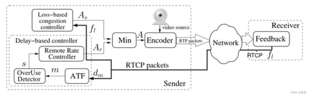
REMB-GCC 是 GCC 的初代版本,采用 "接收端 + 发送端" 分工的架构,核心流程分为接收端延时梯度预估 和发送端丢包率预估两部分,最终发送端取两者最小值作为实际发送码率。
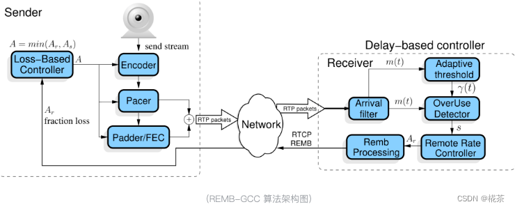
2.1 接收端:基于延时梯度的带宽预估
接收端通过分析数据包的 "发送 - 接收时序差",计算延时梯度,判断网络是否拥塞,并预估最大可用带宽,再通过 RTCP REMB 报文反馈给发送端。核心模块分为 5 个:
(1)Arrival-time Filter(到达时间滤波)
作用 :避免单包时序波动的干扰,基于 "分组" 计算稳定的时间差(而非单包)。
WebRTC 中,发送端会将 RTP 包按5ms 间隔分组发送(由 Pacer 模块控制),接收端同样按 "组" 统计时序信息,核心逻辑如下:
-
分组依据 :通过 RTP 扩展字段
abs-send-time(24bit,精度 3.8us)获取包的发送时间,若某包的发送时间与当前组首包的发送时间差 >5ms,则归为新组。 -
核心数据结构 :
TimestampGroup(存储每组的关键信息):
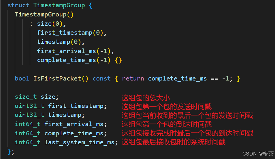
| 字段 | 含义 |
|---|---|
first_timestamp |
组内首包的 RTP 发送时间戳 |
first_arrival_ms |
组内首包的接收时间(毫秒) |
complete_time_ms |
组内最后一包的接收时间(毫秒,代表 "组接收完成时间") |
size |
组内所有包的总大小(字节) |
last_system_time_ms |
组内最后一包的系统接收时间(用于校准时钟偏移) |
-
时间差计算:当新组完成接收后,计算当前组与上一组的:
- 接收时间差:
arrival_delta = current.complete_time_ms - prev.complete_time_ms - 发送时间差:
send_delta = current.first_timestamp - prev.first_timestamp - 包大小差:
size_delta = current.size - prev.size
- 接收时间差:
这些差值将传入下一个模块,用于计算延时梯度。
下面是 WebRTC 计算延时梯度的代码:
cpp
bool InterArrival::ComputeDeltas(uint32_t timestamp,
                                 int64_t arrival_time_ms,
                                 int64_t system_time_ms,
                                 size_t packet_size,
                                 uint32_t* timestamp_delta,
                                 int64_t* arrival_time_delta_ms,
                                 int* packet_size_delta) {
  assert(timestamp_delta != NULL);
  assert(arrival_time_delta_ms != NULL);
  assert(packet_size_delta != NULL);
  bool calculated_deltas = false;
  if (current_timestamp_group_.IsFirstPacket()) {
    // We don't have enough data to update the filter, so we store it until we
    // have two frames of data to process.
    current_timestamp_group_.timestamp = timestamp;
    current_timestamp_group_.first_timestamp = timestamp;
    current_timestamp_group_.first_arrival_ms = arrival_time_ms;
  } else if (!PacketInOrder(timestamp)) {
    return false;
  } else if (NewTimestampGroup(arrival_time_ms, timestamp)) {
    // First packet of a later frame, the previous frame sample is ready.
    if (prev_timestamp_group_.complete_time_ms >= 0) {
      *timestamp_delta =
          current_timestamp_group_.timestamp - prev_timestamp_group_.timestamp;
      *arrival_time_delta_ms = current_timestamp_group_.complete_time_ms -
                               prev_timestamp_group_.complete_time_ms;
      // Check system time differences to see if we have an unproportional jump
      // in arrival time. In that case reset the inter-arrival computations.
      int64_t system_time_delta_ms =
          current_timestamp_group_.last_system_time_ms -
          prev_timestamp_group_.last_system_time_ms;
      if (*arrival_time_delta_ms - system_time_delta_ms >=
          kArrivalTimeOffsetThresholdMs) {
        RTC_LOG(LS_WARNING)
            << "The arrival time clock offset has changed (diff = "
            << *arrival_time_delta_ms - system_time_delta_ms
            << " ms), resetting.";
        Reset();
        return false;
      }
      if (*arrival_time_delta_ms < 0) {
        // The group of packets has been reordered since receiving its local
        // arrival timestamp.
        ++num_consecutive_reordered_packets_;
        if (num_consecutive_reordered_packets_ >= kReorderedResetThreshold) {
          RTC_LOG(LS_WARNING)
              << "Packets are being reordered on the path from the "
                 "socket to the bandwidth estimator. Ignoring this "
                 "packet for bandwidth estimation, resetting.";
          Reset();
        }
        return false;
      } else {
        num_consecutive_reordered_packets_ = 0;
      }
      assert(*arrival_time_delta_ms >= 0);
      *packet_size_delta = static_cast<int>(current_timestamp_group_.size) -
                           static_cast<int>(prev_timestamp_group_.size);
      calculated_deltas = true;
    }
    prev_timestamp_group_ = current_timestamp_group_;
    // The new timestamp is now the current frame.
    current_timestamp_group_.first_timestamp = timestamp;
    current_timestamp_group_.timestamp = timestamp;
    current_timestamp_group_.first_arrival_ms = arrival_time_ms;
    current_timestamp_group_.size = 0;
  } else {
    current_timestamp_group_.timestamp =
        LatestTimestamp(current_timestamp_group_.timestamp, timestamp);
  }
  // Accumulate the frame size.
  current_timestamp_group_.size += packet_size;
  current_timestamp_group_.complete_time_ms = arrival_time_ms;
  current_timestamp_group_.last_system_time_ms = system_time_ms;

  return calculated_deltas;
}
(2)Overuse Estimator(过载估计器)
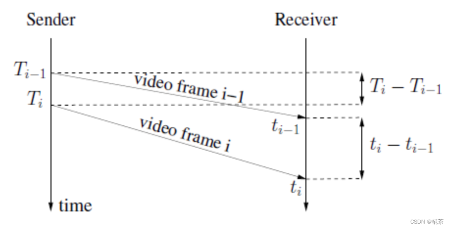
作用 :通过卡尔曼滤波 平滑延时梯度,减少网络噪声(如瞬时抖动)的影响。 核心公式(延时梯度定义):
( d ( t i ) = t i − t i − 1 − T i − T i − 1 ) (d(t_i) = t_i - t_{i-1} - T_i - T_{i-1}) (d(ti)=ti−ti−1−Ti−Ti−1)
- (t_i):第 i 组的接收完成时间;(T_i):第 i 组的首包发送时间;
- 理想网络中 (d(t_i) = 0);网络拥塞时,队列堆积导致 (t_i) 增大,(d(t_i) > 0);网络空闲时 (d(t_i) < 0)。
卡尔曼滤波的作用是对连续多组的 (d(t_i)) 进行平滑处理,输出更稳定的 "拥塞趋势值",避免单组波动导致误判。
OveruseEstimator::Update 函数用于估计延时梯度,它并不是直接使用上一次计算得到的延时梯度值,而是将延时梯度传入该函数,通过卡尔曼滤波算法后得到延时梯度值:
cpp
void OveruseEstimator::Update(int64_t t_delta,
double ts_delta,
int size_delta,
BandwidthUsage current_hypothesis,
int64_t now_ms) {
// 代码省略,详见 src/modules/remote_bitrate_estimator/overuse_estimator.cc
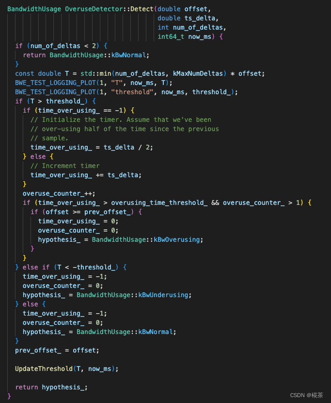
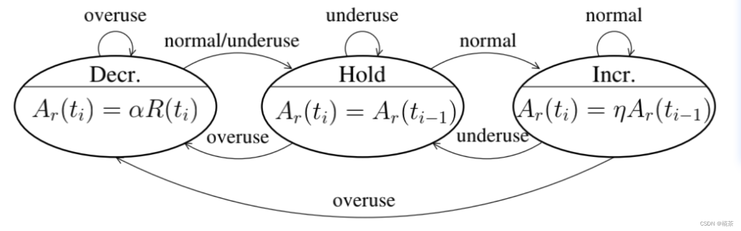
}(3)Overuse Detector(过载检测器)
作用:根据平滑后的延时梯度,判断当前网络状态(3 种状态),判断依据是 "延时梯度与动态阈值的关系"。
| 网络状态 | 判断条件 | 含义 |
|---|---|---|
| Overuse(拥塞) | 1. 平滑后的延时梯度 > 动态阈值; 2. 该状态持续时间 > 阈值(如 100ms); 3. 延时梯度呈增长趋势 | 网络队列持续堆积,需立即降低码率 |
| Underuse(空闲) | 平滑后的延时梯度 < - 动态阈值 | 网络带宽未被充分利用,可维持或小幅提升码率 |
| Normal(正常) | 延时梯度在 - 动态阈值,动态阈值 之间 | 网络处于平衡状态,可缓慢提升码率以探测更大带宽 |
关键 :阈值并非固定值,而是通过 Adaptive Threshold(自适应阈值) 动态调整。
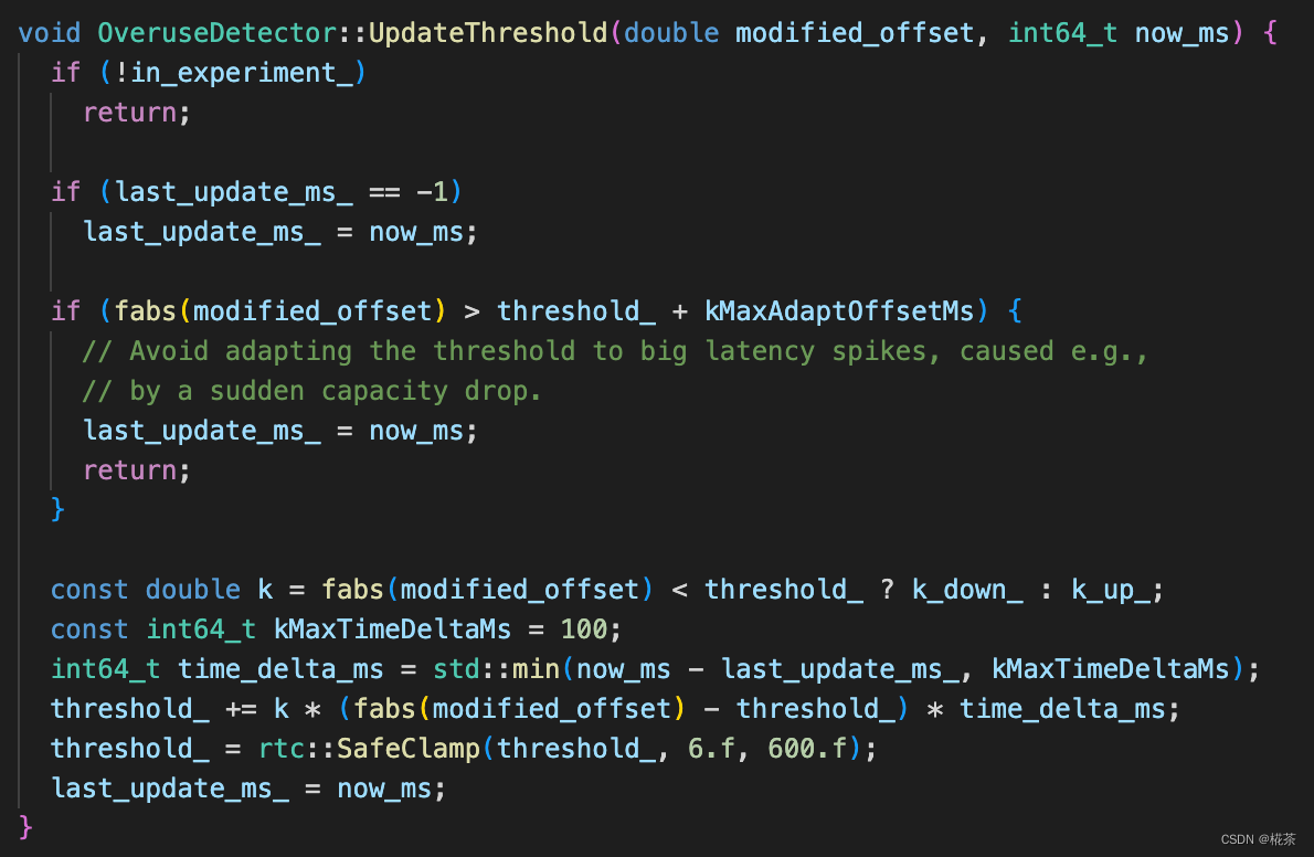
(4)Adaptive Threshold(自适应阈值)
作用:解决 "固定阈值太敏感 / 不敏感" 的问题,根据历史延时梯度动态调整阈值。 核心更新公式:
t h r e s h o l d ( t i ) = t h r e s h o l d ( t i − 1 ) + k ⋅ Δ t ⋅ ( ∣ d ( t i ) ∣ − t h r e s h o l d ( t i − 1 ) threshold(t_i) = threshold(t_{i-1}) + k \cdot \Delta t \cdot (|d(t_i)| - threshold(t_{i-1}) threshold(ti)=threshold(ti−1)+k⋅Δt⋅(∣d(ti)∣−threshold(ti−1)
- Δ t \Delta t Δt:当前组与上一组的时间间隔(毫秒);
- k k k:调整系数(动态变化):
- 若 ∣ d ( t i ) ∣ < t h r e s h o l d ( t i − 1 ) ( N o r m a l 状态): k = 0.00018 |d(t_i)| < threshold(t_{i-1})(Normal 状态):k=0.00018 ∣d(ti)∣<threshold(ti−1)(Normal状态):k=0.00018(阈值缓慢减小,提高灵敏度);
- 若 ∣ d ( t i ) ∣ ≥ t h r e s h o l d ( t i − 1 ) ( O v e r u s e / U n d e r u s e 状态): k = 0.01 |d(t_i)| \geq threshold(t_{i-1})(Overuse/Underuse 状态):k=0.01 ∣d(ti)∣≥threshold(ti−1)(Overuse/Underuse状态):k=0.01(阈值快速增大,避免频繁切换状态)。
通过该逻辑,阈值能自适应网络波动,平衡 "检测灵敏度" 和 "稳定性"。
(5)Remote Rate Controller(远端速率控制器)
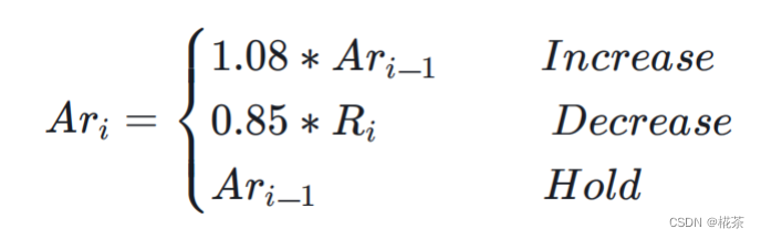
作用 :根据 Overuse Detector 输出的网络状态,计算接收端可承受的最大带宽(REMB 值),调整策略如下:
| 网络状态 | 码率调整策略 |
|---|---|
| Overuse | 降低码率:新码率 = 过去 500ms 内 "已确认接收带宽(acked_bitrate)" × 0.85 |
| Normal | 提升码率:新码率 = 当前码率 × 1.08(缓慢提升,避免突然拥塞) |
| Underuse | 维持码率:不调整(避免盲目提升导致后续拥塞) |
acked_bitrate:接收端通过 RTCP 反馈的 "已成功接收的数据包总大小 / 时间" 计算,反映实际可用带宽
WebRTC 对应的 Rate Controller 调整最大码率的代码如下
cpp
void AimdRateControl::ChangeBitrate(const RateControlInput& input,
                                    Timestamp at_time) {
  absl::optional<DataRate> new_bitrate;
  DataRate estimated_throughput =
      input.estimated_throughput.value_or(latest_estimated_throughput_);
  if (input.estimated_throughput)
    latest_estimated_throughput_ = *input.estimated_throughput;

  // An over-use should always trigger us to reduce the bitrate, even though
  // we have not yet established our first estimate. By acting on the over-use,
  // we will end up with a valid estimate.
  if (!bitrate_is_initialized_ &&
      input.bw_state != BandwidthUsage::kBwOverusing)
    return;

  ChangeState(input, at_time);

  // We limit the new bitrate based on the troughput to avoid unlimited bitrate
  // increases. We allow a bit more lag at very low rates to not too easily get
  // stuck if the encoder produces uneven outputs.
  const DataRate troughput_based_limit =
      1.5 * estimated_throughput + DataRate::KilobitsPerSec(10);

  switch (rate_control_state_) {
    case kRcHold:
      break;

    case kRcIncrease:
      if (estimated_throughput > link_capacity_.UpperBound())
        link_capacity_.Reset();

      // Do not increase the delay based estimate in alr since the estimator
      // will not be able to get transport feedback necessary to detect if
      // the new estimate is correct.
      // If we have previously increased above the limit (for instance due to
      // probing), we don't allow further changes.
      if (current_bitrate_ < troughput_based_limit &&
          !(send_side_ && in_alr_ && no_bitrate_increase_in_alr_)) {
        DataRate increased_bitrate = DataRate::MinusInfinity();
        if (link_capacity_.has_estimate()) {
          // The link_capacity estimate is reset if the measured throughput
          // is too far from the estimate. We can therefore assume that our
          // target rate is reasonably close to link capacity and use additive
          // increase.
          DataRate additive_increase =
              AdditiveRateIncrease(at_time, time_last_bitrate_change_);
          increased_bitrate = current_bitrate_ + additive_increase;
        } else {
          // If we don't have an estimate of the link capacity, use faster ramp
          // up to discover the capacity.
          DataRate multiplicative_increase = MultiplicativeRateIncrease(
              at_time, time_last_bitrate_change_, current_bitrate_);
          increased_bitrate = current_bitrate_ + multiplicative_increase;
        }
        new_bitrate = std::min(increased_bitrate, troughput_based_limit);
      }

      time_last_bitrate_change_ = at_time;
      break;

    case kRcDecrease: {
      DataRate decreased_bitrate = DataRate::PlusInfinity();

      // Set bit rate to something slightly lower than the measured throughput
      // to get rid of any self-induced delay.
      decreased_bitrate = estimated_throughput * beta_;
      if (decreased_bitrate > current_bitrate_ && !link_capacity_fix_) {
        // TODO(terelius): The link_capacity estimate may be based on old
        // throughput measurements. Relying on them may lead to unnecessary
        // BWE drops.
        if (link_capacity_.has_estimate()) {
          decreased_bitrate = beta_ * link_capacity_.estimate();
        }
      }
      if (estimate_bounded_backoff_ && network_estimate_) {
        decreased_bitrate = std::max(
            decreased_bitrate, network_estimate_->link_capacity_lower * beta_);
      }

      // Avoid increasing the rate when over-using.
      if (decreased_bitrate < current_bitrate_) {
        new_bitrate = decreased_bitrate;
      }

      if (bitrate_is_initialized_ && estimated_throughput < current_bitrate_) {
        if (!new_bitrate.has_value()) {
          last_decrease_ = DataRate::Zero();
        } else {
          last_decrease_ = current_bitrate_ - *new_bitrate;
        }
      }
      if (estimated_throughput < link_capacity_.LowerBound()) {
        // The current throughput is far from the estimated link capacity. Clear
        // the estimate to allow an immediate update in OnOveruseDetected.
        link_capacity_.Reset();
      }

      bitrate_is_initialized_ = true;
      link_capacity_.OnOveruseDetected(estimated_throughput);
      // Stay on hold until the pipes are cleared.
      rate_control_state_ = kRcHold;
      time_last_bitrate_change_ = at_time;
      time_last_bitrate_decrease_ = at_time;
      break;
    }
    default:
      assert(false);
  }

  current_bitrate_ = ClampBitrate(new_bitrate.value_or(current_bitrate_));
}
(6)Remb Processing(REMB 报文处理)
接收端计算出最大带宽后,通过 RTCP REMB 报文 反馈给发送端,核心细节:
- 报文类型:RTCP 扩展报文,PT(Payload Type)=206,FMT(Format)=15;
- 关键字段 :
Unique Identifier:固定为 0x52454D42(即 "REMB" 的 ASCII 码);BR Exp+BR Mantissa:共同表示最大带宽(单位:bps),计算公式:带宽 = Mantissa × 2^Exp;SSRC feedback:需要限制码率的发送端 SSRC 列表(支持多流场景);
- 发送频率:默认每 200ms 发送一次;若检测到新带宽 < 上一次的 97%(拥塞加剧),则立即发送。
具体报文格式如下:
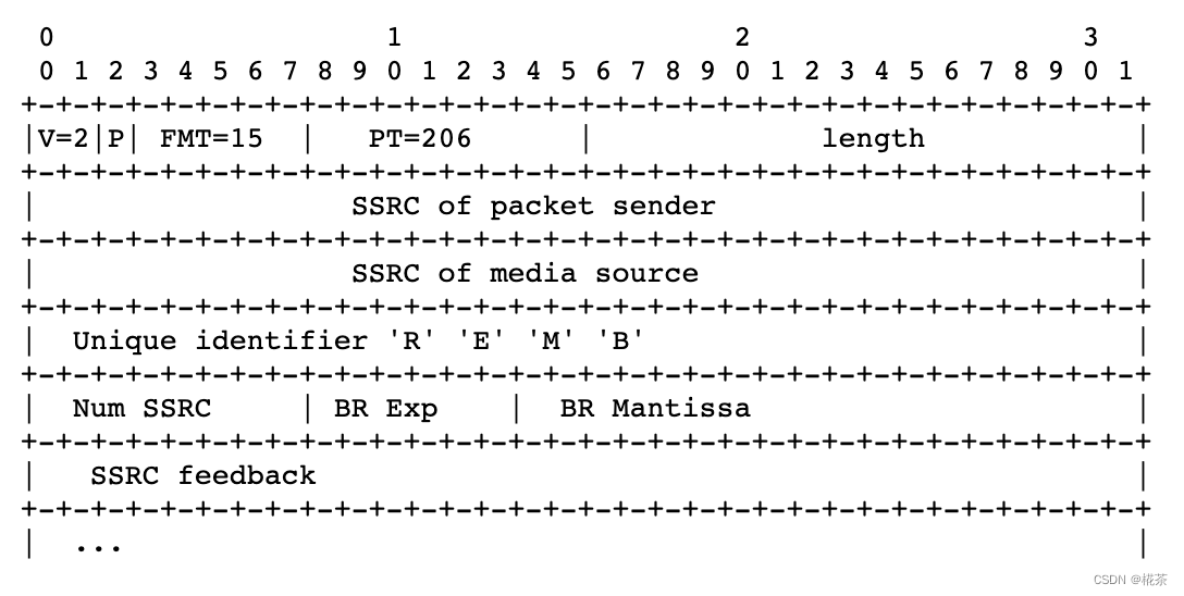
WebRTC 中 RTCP REMB 报文一般是每 200ms 反馈一次,但是当检测到可用带宽小于上次预估的 97% 时则会立刻反馈
2.2 发送端:基于丢包率的带宽预估
发送端除了接收 REMB 反馈的带宽,还会独立基于丢包率 预估带宽,最终取两者的最小值作为实际发送码率(双重保险)。
(1)丢包率获取
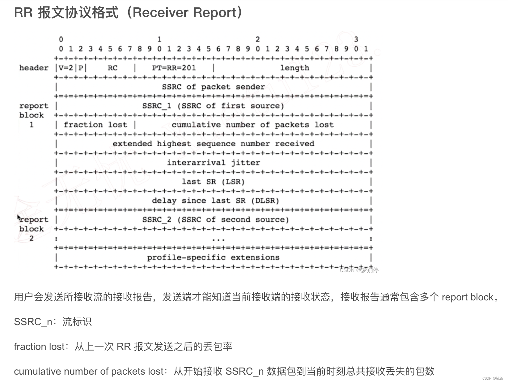
发送端通过 RTCP RR 报文 (Receiver Report)的 fraction lost 字段获取丢包率:
fraction lost:8bit 无符号数,表示 "从上一次 RR 到本次 RR 期间,丢失的数据包占总发送包的比例";- 计算方式:
丢包率 = fraction lost / 256 × 100%(精度约 0.39%)。
RR报文格式如下:
(2)码率调整策略
根据丢包率判断网络状态,调整发送码率:
| 丢包率范围 | 网络状态 | 码率调整策略 |
|---|---|---|
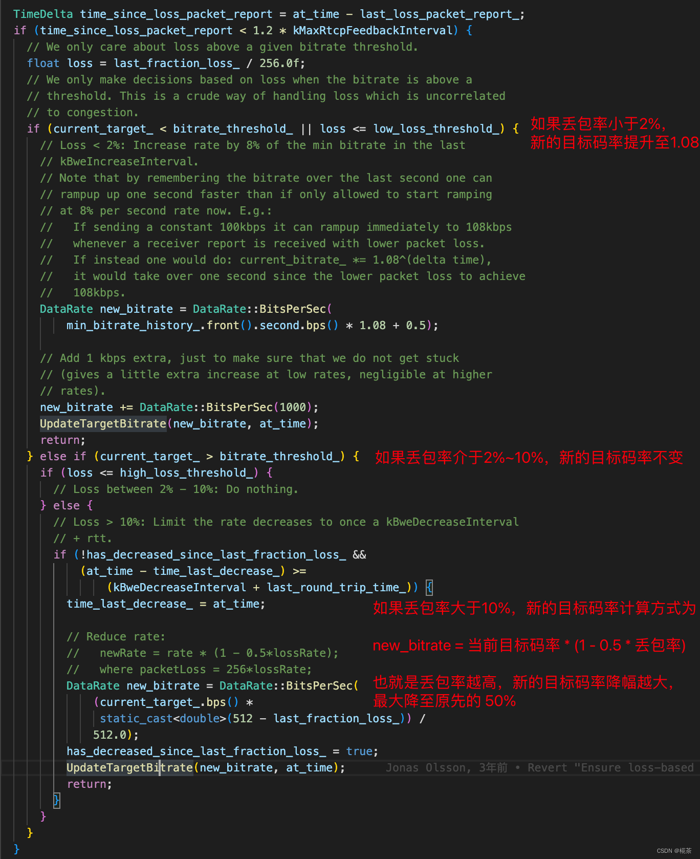
| >10% | 严重拥塞 | 大幅降码率:新码率 = 当前码率 × 0.5(快速减少发送量,缓解拥塞) |
| 2% ~ 10% | 轻度拥塞 | 小幅降码率:新码率 = 当前码率 × 0.85(缓慢调整,平衡带宽与稳定性) |
| <2% | 网络空闲 | 提升码率:新码率 = 当前码率 × 1.1(探测更大带宽,避免浪费) |
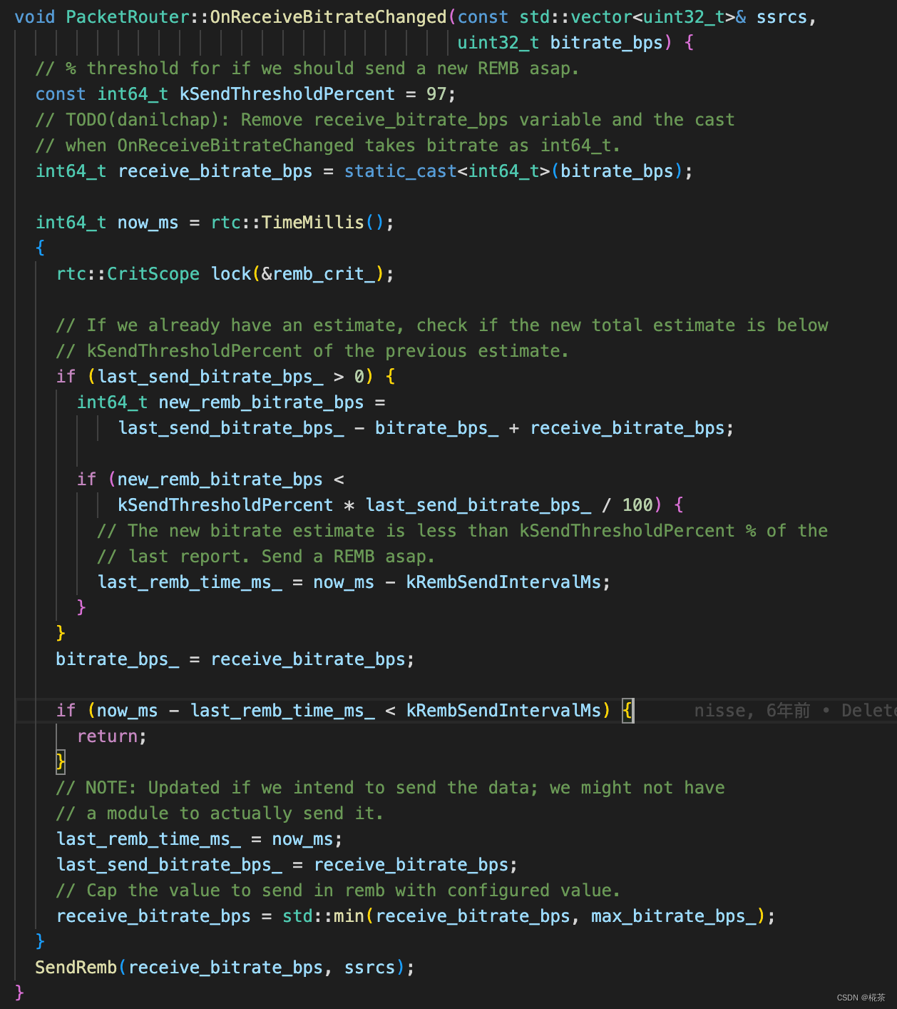
| 对于目标码率的调整方式,WebRTC 处理代码如下所示 |
(3)最终码率确定
发送端将 "接收端 REMB 带宽" 与 "本地丢包率预估带宽" 比较,取较小值作为最终发送码率,并同步给:
- Encoder(编码器):调整视频分辨率、帧率或码率因子(如 H.264 的 CRF);
- Pacer(发送 pacing 模块):控制数据包的发送节奏,避免突发发送导致队列堆积;
- FEC(前向纠错):根据码率调整 FEC 冗余度,提升抗丢包能力。
三、TCC-GCC 算法原理(主流版本)
REMB-GCC 存在明显缺陷:接收端需承担带宽预估计算,且 REMB 报文仅反馈 "最大带宽",缺乏精细化时序信息。因此 Google 推出 TCC-GCC(Transport-wide Congestion Control),作为当前 WebRTC 的默认方案。
3.1 TCC-GCC 与 REMB-GCC 的核心差异
| 对比维度 | REMB-GCC | TCC-GCC |
|---|---|---|
| 带宽预估位置 | 接收端(延时梯度)+ 发送端(丢包率) | 仅发送端(统一处理延时梯度 + 丢包率) |
| 接收端反馈内容 | 仅 "最大带宽(REMB 值)" | 详细收包时序(TCC 报文:包的发送 / 接收时间) |
| 反馈报文 | RTCP REMB | RTCP TCC(Transport-wide CC) |
| 计算复杂度 | 接收端 / 发送端均有复杂度 | 接收端无复杂度,发送端集中计算 |
| 精度 | 较低(依赖接收端预估,信息有限) | 较高(发送端掌握全量时序,可做更精细判断) |
3.2 TCC-GCC 的核心流程
- 发送端打标 :为每个 RTP 包分配一个全局唯一的 Transport Sequence Number(TSN) ,并记录包的发送时间(
send_time); - 接收端反馈 :接收端按 TSN 顺序统计收包情况,生成 RTCP TCC 报文 ,包含:
- 每个 TSN 的接收时间(
recv_time); - 丢包标记(哪些 TSN 未收到);
- 每个 TSN 的接收时间(
- 发送端计算 :发送端根据 TCC 报文的
send_time和recv_time,计算延时梯度(逻辑与 REMB-GCC 一致),同时结合丢包率,统一预估带宽; - 码率调整:发送端直接根据预估带宽调整 Encoder、Pacer 等模块,无需与接收端带宽取最小值。
3.3 TCC-GCC 的优势
- 减少接收端负担:尤其适合弱终端(如手机、IoT 设备),接收端仅需统计时序,无需复杂计算;
- 更高精度:发送端掌握全量包的发送 / 接收时序,可更精准判断拥塞趋势(如区分 "网络抖动" 和 "持续拥塞");
- 支持多流统一控制:同一 Transport 下的多 RTP 流(如视频 + 音频)可共享 TCC 反馈,实现全局拥塞控制。
四、GCC 的应用与优势
4.1 适用场景
GCC 专为实时音视频设计,核心适用场景包括:
- 视频会议(如 Zoom、Teams、WebRTC 会议系统);
- 实时直播(如游戏直播、互动直播);
- 低延迟互动场景(如在线教育、远程控制)。
4.2 核心优势
- 低延迟优先:通过延时梯度提前感知拥塞,避免丢包(丢包会导致重传,增加延迟);
- 带宽利用率高:Normal 状态下缓慢提升码率,最大化利用空闲带宽;
- 自适应网络:动态阈值和双指标融合,适应复杂网络(如 4G/5G、WiFi、公网);
- 与实时场景适配:不依赖 TCP 重传,通过 FEC/RTX(重传)配合,平衡延迟与可靠性。