1 缘由
教程里面用的是OV7675,不过有点贵,是国产的OV7670价格的10倍不止。所以这里打算换成国产的OV7670。两个都是OmniVision 0.3MP VGA 级CMOS图像传感器。
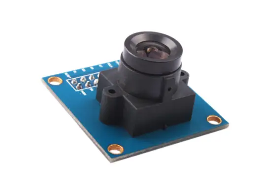
OV7670 用的是老一代6µm像素工艺,光敏面积大,但芯片体积大。OV7675 用的是更新的3µm工艺,在小尺寸模组里更合适,噪声和功耗控制更好。所以两者最大的差异就是制作工艺,7675体积也更小。不过两者并不是Pin2Pin兼容。
2 硬件连接
OV7670引脚说明:
- 控制接口(I2C):SCL(时钟线)、SDA(数据线)、VCC(电源)、GND(接地)。
- 数据接口(并行):D0-D7(8 位数据)、VSYNC(场同步)、HREF(行参考)、PCLK(像素时钟)、RST(复位,可选)、PWDN(省电,接低电平启用)。
有专门的一篇文章说怎么修改:https://blog.arduino.cc/2020/06/24/machine-vision-with-low-cost-camera-modules/
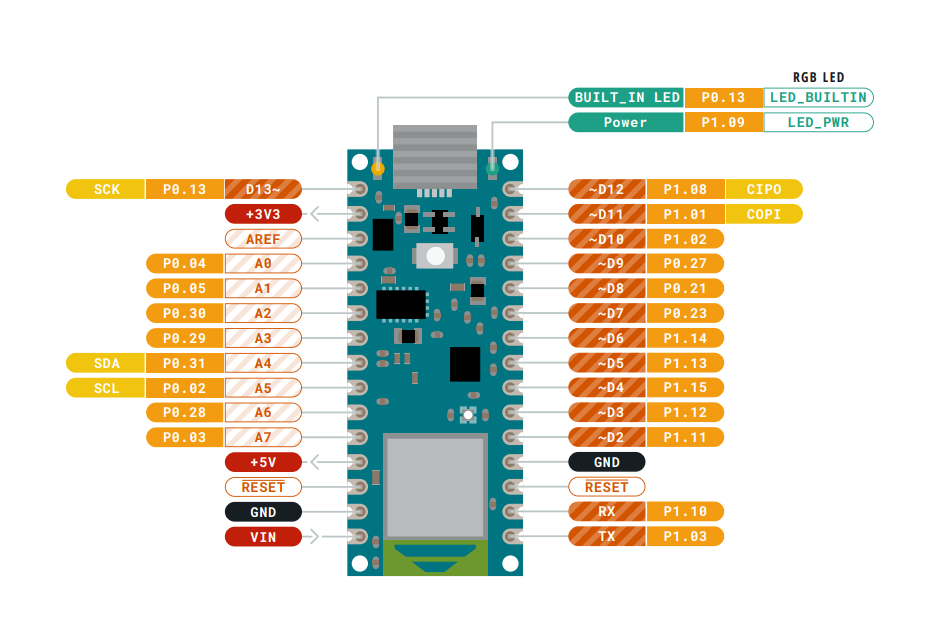
Nano BLE的Pins定义如下:
按照上面那篇文章,接线图如下:
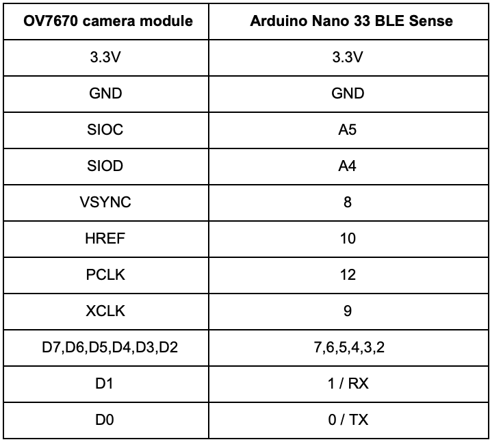
但是这个Pin脚定义好像不对,因为直接初始化就挂了。
if (!Camera.begin(QVGA, RGB565, 1)) {
Serial.println("Failed to initialize camera!");
while (1);
}
看了一下代码,好像说了一下Pin脚的配置,和上面的差很多。
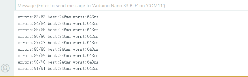
Test that the connection between your Arduino and Camera is able to transfer data correctly at the given speed
Circuit:
Arduino Nano 33 BLE board
OV7670 camera module:
3.3 connected to 3.3
GND connected GND
SIOC connected to A5
SIOD connected to A4
VSYNC connected to 8
HREF connected to A1
PCLK connected to A0
XCLK connected to 9
D7 connected to 4
D6 connected to 6
D5 connected to 5
D4 connected to 3
D3 connected to 2
D2 connected to 0 / RX
D1 connected to 1 / TX
D0 connected to 10
This example code is in the public domain.
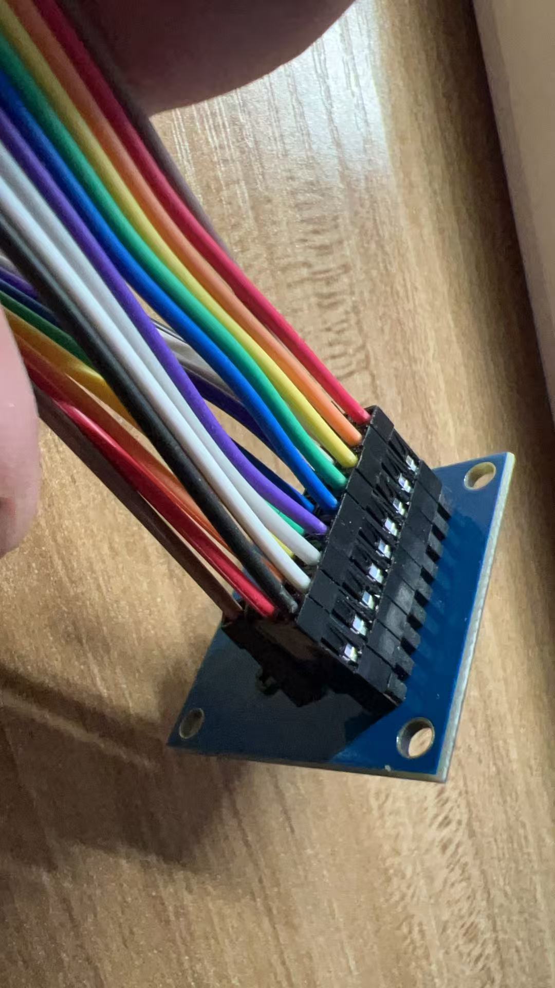
试了一下。我是真想吐槽的,因为引脚真的太多了。。。一共快20个了。连接这堆杜邦线都要搞好久。。。
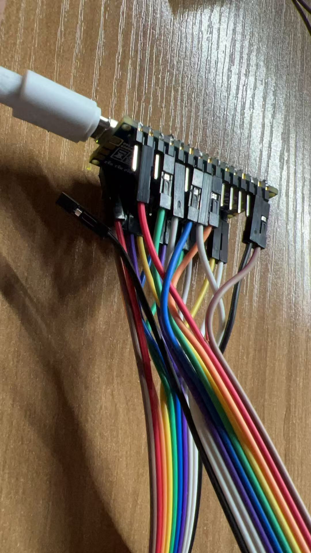
上去起码不报错了。
3 软件配置
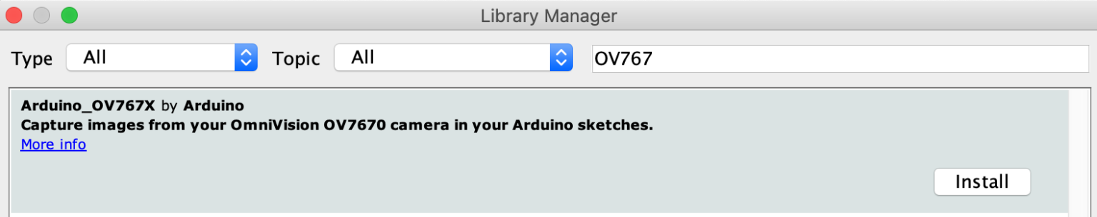
软件上首先要多安装一个OV765X的库。
其实还要装一个Arduino_CRC32的库,里面有例子会用到。
之后就可以看到出的图了。
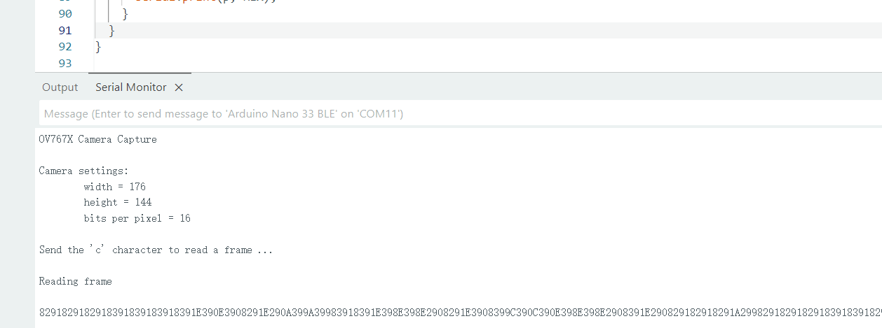
但是这个图是乱码,怎么看呢。看了一下之前那个教程,说是有个Processing软件可以看。
Processing 是由麻省理工学院媒体实验室开发的开源图形设计语言与开发环境,2001 年诞生至今始终免费,支持跨平台运行。它以简化的 Java 语法为基础,无需深厚编程基础也能快速上手,核心通过
setup()(初始化)和draw()(循环渲染)函数实现图形绘制、动画效果与交互功能,还可借助扩展库拓展音频处理、3D 渲染等能力,广泛用于艺术创作(如视觉装置、动态图形)、设计领域(如交互设计原型)及编程教育,是连接代码与视觉表达的实用工具。
下载地址是:https://processing.org/
01年的软件,老掉牙了属于,不过还能用吧。
这个要放置一套Java代码进去。
java
/*
  This sketch reads a raw Stream of RGB565 pixels
  from the Serial port and displays the frame on
  the window.

  Use with the Examples -> CameraCaptureRawBytes Arduino sketch.

  This example code is in the public domain.
*/

import processing.serial.*;
import java.nio.ByteBuffer;
import java.nio.ByteOrder;

Serial myPort;

// must match resolution used in the sketch
final int cameraWidth = 320;
final int cameraHeight = 240;
final int cameraBytesPerPixel = 2;
final int bytesPerFrame = cameraWidth * cameraHeight * cameraBytesPerPixel;

PImage myImage;
byte[] frameBuffer = new byte[bytesPerFrame];

void setup()
{
  size(320, 240);

  // if you have only ONE serial port active
  //myPort = new Serial(this, Serial.list()[0], 9600);          // if you have only ONE serial port active

  // if you know the serial port name
  myPort = new Serial(this, "COM11", 9600);                    // Windows
  //myPort = new Serial(this, "/dev/ttyACM0", 9600);            // Linux
  //myPort = new Serial(this, "/dev/cu.usbmodem14401", 9600);     // Mac

  // wait for full frame of bytes
  myPort.buffer(bytesPerFrame);

  myImage = createImage(cameraWidth, cameraHeight, RGB);
}

void draw()
{
  image(myImage, 0, 0);
}

void serialEvent(Serial myPort) {
  // read the saw bytes in
  myPort.readBytes(frameBuffer);

  // access raw bytes via byte buffer
  ByteBuffer bb = ByteBuffer.wrap(frameBuffer);
  bb.order(ByteOrder.BIG_ENDIAN);

  int i = 0;

  while (bb.hasRemaining()) {
    // read 16-bit pixel
    short p = bb.getShort();

    // convert RGB565 to RGB 24-bit
    int r = ((p >> 11) & 0x1f) << 3;
    int g = ((p >> 5) & 0x3f) << 2;
    int b = ((p >> 0) & 0x1f) << 3;

    // set pixel color
    myImage .pixels[i++] = color(r, g, b);
  }
 myImage .updatePixels();

}
我是Windows,用的COM11,所以改成myPort = new Serial(this, "COM11", 9600);
打开OV767X - Camera Capture Raw Bytes这个例子,编译上传之后关掉Arduino,运行这个程序,就可以看到图了。
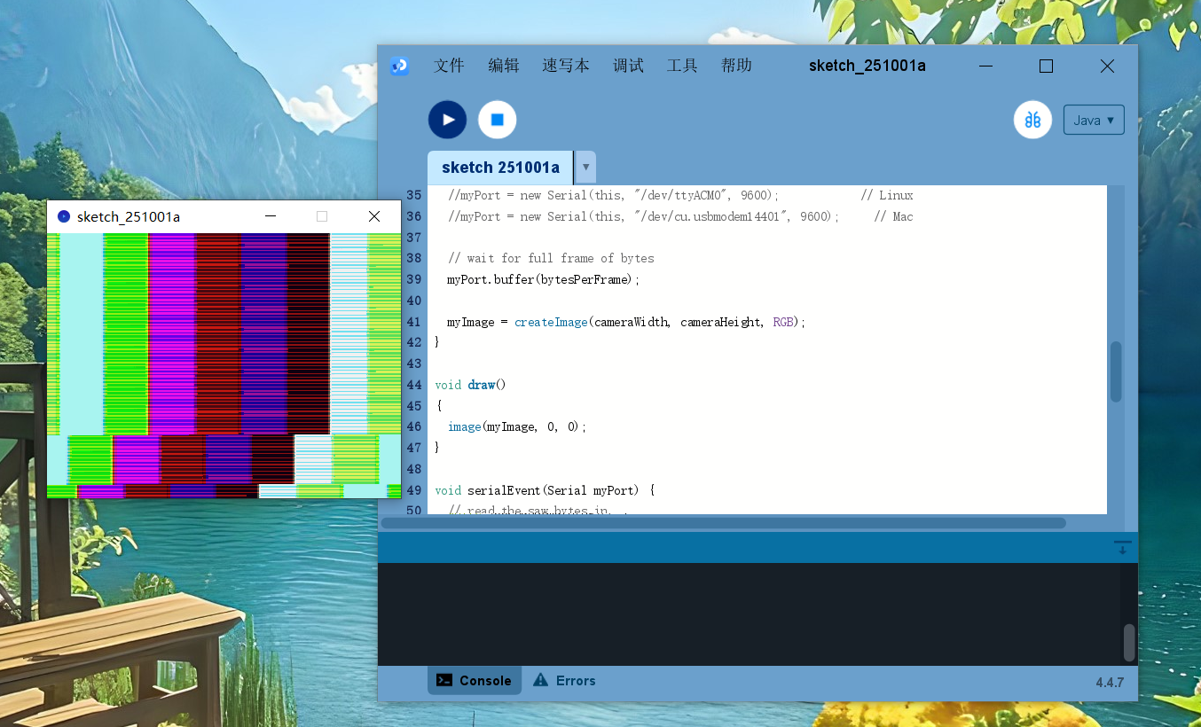
如果屏蔽掉// Camera.testPattern();是下面的。
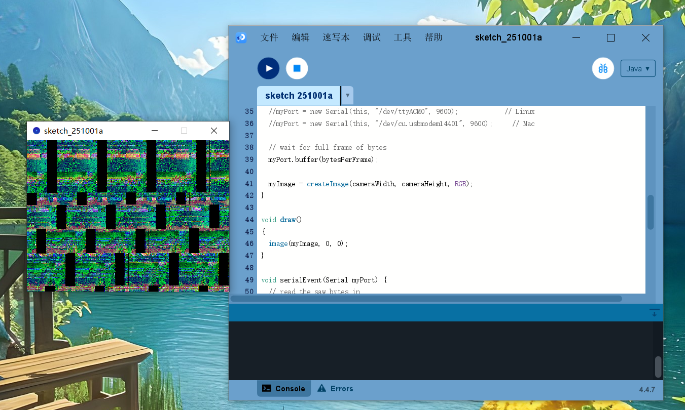
可以看到,数据是能出来了,但是花屏了,明显还不对。。。
未完待续。。。