文章目录
-
- [HDLBit 个人记录](#HDLBit 个人记录)
- [Verilog Languages](#Verilog Languages)
-
- [More verilog features](#More verilog features)
- Vectors
- Circuits
-
- [Combinational logic](#Combinational logic)
- [Sequential logic](#Sequential logic)
-
- [lateches and Flip-Flops](#lateches and Flip-Flops)
- Counter
- [Shift registers](#Shift registers)
- [More circuits](#More circuits)
- [Finite state machine](#Finite state machine)
-
- [`Simple FSM1: synchronous reset.`](#
Simple FSM1: synchronous reset.) - [`Designing a Moore FSM`](#
Designing a Moore FSM) - [`Lemming 2`](#
Lemming 2) - [`Lemming 3`](#
Lemming 3) - [`lemming 4`](#
lemming 4) - [one-hot FSM](#one-hot FSM)
- [PS/2 packet parser](#PS/2 packet parser)
- [ps/2 parser and data path](#ps/2 parser and data path)
- [serial receiver](#serial receiver)
- [serial receiver and data path](#serial receiver and data path)
- [Serial receiver with parity check](#Serial receiver with parity check)
- [Q8: Design a Mealy FSM](#Q8: Design a Mealy FSM)
- [q5a: serial two's complement (moore FSM)](#q5a: serial two's complement (moore FSM))
- [q5a: serial two's complement (Mealy FSM)](#q5a: serial two's complement (Mealy FSM))
- [q3a: FSM](#q3a: FSM)
- [Q6 FSM (Q2a FSM)](#Q6 FSM (Q2a FSM))
- [Q2b Another FSM](#Q2b Another FSM)
- [`Simple FSM1: synchronous reset.`](#
HDLBit 个人记录
HDLBit网站上有时候会用system verilog的语法,和verlog2001的语法标准有区别。可以注册账号,写的代码就可以保存在云端了。
Verilog Languages
More verilog features
Generate for-loops: 100 BCD adders: 将第一个addder特殊处理
verilog
module top_module(
    input [399:0] a, b,
    input cin,
    output cout,
    output [399:0] sum );
    wire[99:0] c;
    bcd_fadd f(a[3:0], b[3:0], cin, c[0], sum[3:0]);
    genvar i;
    generate
        for(i=1; i<100; i=i+1) begin: adder
            bcd_fadd f1(a[(4*i+3):(4*i)], b[(4*i+3):(4*i)], c[i-1], c[i], sum[(4*i+3):(4*i)]);
        end
    endgenerate
    assign cout = c[99];
endmodule
Vectors
- More Replication: 使用复制写法
verilog
module top_module (
    input a, b, c, d, e,
    output [24:0] out );//

    // The output is XNOR of two vectors created by
    // concatenating and replicating the five inputs.
    // assign out = ~{ ... } ^ { ... };
    assign out = ~{5{a, b, c, d ,e}} ^ {{5{a}}, {5{b}}, {5{c}}, {5{d}}, {5{e}}};
endmodule
Circuits
Combinational logic
Multiplexers
256-to-1 multiplexer.:verilog2001中有part select语法
verilog
module top_module(
    input [1023:0] in,
    input [7:0] sel,
    output [3:0] out );
    assign out = in[sel*4 +:4];
endmodule
Sequential logic
lateches and Flip-Flops
Dual edge:这个我没想出来,看了解析,利用了异或的特性x=x^y^y
verilog
module top_module (
    input clk,
    input d,
    output q
);
    reg q1, q2;
    always @(posedge clk) begin
        q1 <= d ^ q2;
    end
    always @(negedge clk) begin
        q2 <= d ^ q1;
    end
    assign q = q1 ^ q2;
endmodule
Counter
12-hour clock:时分秒的判断逻辑,此外reset和ena互斥。
verlog
module top_module(
    input clk,
    input reset,
    input ena,
    output pm,
    output [7:0] hh,
    output [7:0] mm,
    output [7:0] ss);
    always @(posedge clk) begin
        if(reset) begin
            pm <= 0;
            ss <= 0;
            mm <= 0;
            hh <= 'h12;
        end
        else if (ena) begin
            ss <= (ss[3:0]==9)? {ss[7:4]+1,4'b0}: ss+1;
            if(ss=='h59)begin
                ss <= 0;
                mm <= mm[3:0]==9? {mm[7:4]+1,4'b0}: mm+1;
                if(mm=='h59) begin
                    mm <= 0;
                    hh <= hh[3:0]==9? {hh[7:4]+1,4'b0}: hh+1;
                    if(hh=='h11) pm <= ~pm;
                    if(hh=='h12) hh <= 'h01;
                end
            end
        end
    end
endmodule
Shift registers
5bit LFSR:5比特线性反馈移位器,我将组合逻辑直接放在了always时序逻辑块里,网站提供了参考答案将这部分组合逻辑剥离到另一个always组合逻辑块里。
verilog
module top_module(
    input clk,
    input reset,    // Active-high synchronous reset to 5'h1
    output [4:0] q
);
    always @(posedge clk) begin
        if (reset ) q<=5'd1;
        else begin
            q <= {q[0], q[4], q[3] ^ q[0], q[2], q[1]};
        end
    end
endmodule
shift registers:使用generate生成同一种器件。
verilog
module top_module (
    input [3:0] SW,
    input [3:0] KEY,
    output [3:0] LEDR
); //
    wire[3:0] ws;
    assign ws[3] = KEY[3];
    assign ws[2] = LEDR[3];
    assign ws[1] = LEDR[2];
    assign ws[0] = LEDR[1];

	genvar i;
    generate
        for(i=0; i<4; i++) begin: m
            MUXDFF mu(KEY[0],
                      ws[i], SW[i], KEY[1], KEY[2],
                      LEDR[i]
                     );
        end
    endgenerate
endmodule

module MUXDFF (
    input clk,
    input w, R, E, L,
    output Q);
    always @(posedge clk) begin
        Q <= L? R : (E? w:Q);
    end
endmodule
3 input LUT:Z赋值时需要在always块外部,才能构造组合逻辑,否则在块内部会综合出寄存器,导致输出延迟一个周期。
verilog
module top_module (
    input clk,
    input enable,
    input S,
    input A, B, C,
    output Z );
    reg[7:0] Q;
    always @(posedge clk) begin
        if (enable) Q <= {Q[6:0], S};
    end
    assign Z = Q[{A, B, C}];
endmodule
More circuits
Rule90:按照题目提供的规律,构造异或组合逻辑。
verilog
module top_module(
    input clk,
    input load,
    input [511:0] data,
    output [511:0] q );
    always @(posedge clk) begin
        if(load) q <= data;
        else q <= {1'b0, q[511:1]} ^ {q[510:0], 1'b0};
    end
endmoduleRule110:观察规律,发现0值的情况仅有3种,用0值写出组合逻辑。
verilog
module top_module(
    input clk,
    input load,
    input [511:0] data,
    output [511:0] q
);
    wire[511:0] q1, q2;
    assign q1 = {1'b0, q[511:1]};
    assign q2 = {q[510:0], 1'b0};
    always @(posedge clk) begin
        if(load) q<=data;
        else begin
            q <= ~((q1 & q & q2) | ~(q | q2));
        end
    end
endmodule
Conway's Game of Life:利用过程赋值中的阻塞赋值构建组合电路。
verilog
module top_module(
    input clk,
    input load,
    input [255:0] data,
    output [255:0] q );
    always @(posedge clk) begin
        if(load) q <= data;
        else begin
            integer i, j;
            for(i=0; i<16; i=i+1) begin
                for(j=0; j< 16; j=j+1) begin
                    integer i1, i2, j1, j2, n;
                    i1 = (i+15)%16;
                    i2 = (i+1)%16;
                    j1 = (j+15)%16;
                    j2 = (j+1)%16;
                    n = q[i1*16+j1] + q[i1*16+j] + q[i1*16+j2] + q[i2*16+j1] + q[i2*16+j] + q[i2*16+j2] + q[i*16+j1] + q[i*16+j2];
                    case(n)
                        2: q[i*16+j] <= q[i*16+j];
                        3: q[i*16+j] <= 1'b1;
                        default: q[i*16+j] <= 1'b0;
                    endcase
                end
            end
        end
    end
endmodule
Finite state machine
- Moore状态机的输出只与当前状态有关,与当前输入无关
- Mealy状态机的输出不仅与当前状态有关,还取决于当前的输入信号。输入信号变化后,输出会立即发生变化,因此Mealy状态机的输出响应比Moore状态机快一个时钟周期。
Simple FSM1: synchronous reset.
- 给的示例程序将组合逻辑混入了时序逻辑块里,极易出错。
verilog
// Note the Verilog-1995 module declaration syntax here:
module top_module(clk, reset, in, out);
    input clk;
    input reset;    // Synchronous reset to state B
    input in;
    output out;//
    reg out;

    // Fill in state name declarations
	parameter A=0, B=1;
    reg present_state, next_state;

    always @(posedge clk) begin
        if (reset) begin
            // Fill in reset logic
            present_state <= B;
            out <= B;
        end else begin
            case (present_state)
                // Fill in state transition logic
                A: next_state = in? A : B; // 这里不可用<=赋值,会使得赋值出现在present_state = next_state; 之后,
                B: next_state = in? B : A; // gemini说这种写法极易出现错误,建议使用3段式
            endcase

            // State flip-flops
            present_state = next_state;

            case (present_state)
                // Fill in output logic
                A: out <= A;
                B: out <= B;
            endcase
        end
    end

endmodule
Designing a Moore FSM
- 水位状态可以直接从
s由组合逻辑给出,只有dfr需要记录前序状态,但是debugdfr花了很久时间,参考了网上的解答才发现要初始化,其实题目最后一句提到了dfr在reset要被赋值,但是被我忽略了。此外,网站给的解答是将中间两个水位结合dfr组成新的状态,上下两个水位dfr固定。
verilog
module top_module (
    input clk,
    input reset,
    input [3:1] s,
    output fr3,
    output fr2,
    output fr1,
    output dfr
);
	parameter OFF=0, ON=1;
    reg state, next_state;
    reg[3:1] s_pre;
    /* 这种组合赋值没有延迟,不符合测例要求
    assign fr3 = ~s[1];
    assign fr2 = ~s[2];
    assign fr1 = ~s[3];
    */
    always @(*) begin
        next_state = s > s_pre? OFF: (s<s_pre? ON: state);
    end

    always @(posedge clk) begin
        if(reset) begin
            state<=ON;
            s_pre <= 0; //非常重要,这个设定的初值用于判断后续对的dfr初值。
            {fr1, fr2, fr3} <= {3{1'b1}};
        end
        else begin
            s_pre <= s;
            state<=next_state;
            {fr1, fr2, fr3} <= ~s;
        end
    end
    assign dfr = state;
endmodule
Lemming 2
- 精巧设计状态值,为下落划分两个状态,因为题目需要下落后保持原有的方向,所以如果下落简并为1个状态时,那么就会无法记忆原有的方向信息。
verilog
module top_module(
    input clk,
    input areset,    // Freshly brainwashed Lemmings walk left.
    input bump_left,
    input bump_right,
    input ground,
    output walk_left,
    output walk_right,
    output aaah );
    //设置状态的值,使得L_F和L(R_F和R)的末位一致,在组合逻辑里可以应用,而L_F和R_F的高位为1,在后面aaah赋值用到
    // parameter要指定位宽,否则会出现隐藏的问题,比如后续为next_state赋值R_F: next_state = {1'b0, state[0]}就会不正常
	parameter L=2'd0, R=2'd1, L_F=2'd2, R_F=2'd3;
    reg[1:0] state, next_state;
    always @(*) begin
        if (~ground) next_state = {1'b1, state[0]};//L->L_F,R->R_F
        else begin
            case(state)
                L_F: next_state = L;
                R_F: next_state = R;
                L: next_state = bump_left? R: L;
                R: next_state = bump_right? L: R;
            endcase
       end
    end

    always @(posedge clk, posedge areset) begin
        if(areset) state <= L;
        else state <= next_state;
    end

    assign walk_left = (state==L);
    assign walk_right = (state==R);
    assign aaah = (state[1]==1'b1);
endmodule
Lemming 3
- 注意dig的状态转换
verilog
module top_module(
    input clk,
    input areset,    // Freshly brainwashed Lemmings walk left.
    input bump_left,
    input bump_right,
    input ground,
    input dig,
    output walk_left,
    output walk_right,
    output aaah,
    output digging );
    //引入下落状态,保证最后一位存L, R的信息
	parameter L=3'd0, R=3'd1, L_F=3'd2, R_F=3'd3, L_D= 3'b100, R_D=3'b101;
    reg[2:0] state, next_state;
    always @(*) begin
        if (~ground) next_state = {2'b01, state[0]};//L->L_F,R->R_F,L_D->L_F,R_D->R_F
        else if(dig & ~state[1]) next_state = {2'b10, state[0]}; //对比时序图可知,下落过程会在ground出现时存在,但是仍然无法开始dig
        else begin
            case(state)
                L_D: next_state = L_D; // dig的优先级高,保持该状态
                R_D: next_state = R_D;
                L_F: next_state = L;
                R_F: next_state = R;
                L: next_state = bump_left? R: L;
                R: next_state = bump_right? L: R;
            endcase
       end
    end

    always @(posedge clk, posedge areset) begin
        if(areset) state <= L;
        else state <= next_state;
    end

    assign walk_left = (state==L);
    assign walk_right = (state==R);
    assign aaah = (state[1]==1'b1);
    assign digging = (state[2]==1'b1);
endmodule
lemming 4
- 注意赋值时的位宽,极易出错
verilog
module top_module(
    input clk,
    input areset,    // Freshly brainwashed Lemmings walk left.
    input bump_left,
    input bump_right,
    input ground,
    input dig,
    output walk_left,
    output walk_right,
    output aaah,
    output digging );
    //引入下落状态,保证最后一位存L, R的信息,splat不需要保存LR信息,且优先级最高
	parameter L=3'd0, R=3'd1, L_F=3'd2, R_F=3'd3, L_D= 3'b100, R_D=3'b101, SPLAT=3'b110, die_height=5'd20;
    reg[2:0] state, next_state;
    reg[4:0] counter;
    wire wait_splat;
    // 下面是组合逻辑 连线
    assign wait_splat = (counter==die_height)? 1'b1: 1'b0;
    always @(*) begin
        if (state==SPLAT) next_state = SPLAT;
        else if (~ground) next_state = {2'b01, state[0]};//L->L_F,R->R_F,L_D->L_F,R_D->R_F
        else if (wait_splat) next_state = SPLAT; //接触地面时转换
        else if(dig & ~state[1]) next_state = {2'b10, state[0]}; //对比时序图可知,下落过程会在ground出现时存在,但是仍然无法开始dig
        else begin
            case(state)
                SPLAT: next_state= SPLAT;
                L_D: next_state = L_D; // dig的优先级高,保持该状态
                R_D: next_state = R_D;
                L_F: next_state = L;
                R_F: next_state = R;
                L: next_state = bump_left? R: L;
                R: next_state = bump_right? L: R;
                default: next_state = 'x; //这里的case可以避免verilog综合出latch
            endcase
       end
    end
    // 下面是时序逻辑 连线
    always @(posedge clk, posedge areset) begin
        if(areset) begin
            state <= L;
            counter <= 0;
        end
        else begin
            state <= next_state;
            counter <= (state[2:1]==2'b01)? ((counter!=die_height)? counter + 1'b1 :counter): 4'd0;
        end
    end

    assign walk_left = (state==L);
    assign walk_right = (state==R);
    assign aaah = (state[2:1]==2'b01);
    assign digging = (state[2:1]==2'b10);
endmodule
one-hot FSM
- 题目要求观察位之间的运算关系,所以按照之前FSM设计自定义组合逻辑块是无法通过测例的,必须使用位运算逻辑。
verilog
module top_module(
    input in,
    input [9:0] state,
    output [9:0] next_state,
    output out1,
    output out2);
    /*
    parameter S0=10'd1, S1=10'd2, S2=10'd4, S3=10'd8, S4=10'd16, S5=10'd32, S6=10'd64, S7=10'd128, S8=10'd256, S9=10'd512;
    always @(*) begin
        case(state)
            S0: next_state = in? S1: S0;
            S1: next_state = in? S2: S0;
            S2: next_state = in? S3: S0;
            S3: next_state = in? S4: S0;
            S4: next_state = in? S5: S0;
            S5: next_state = in? S6: S8;
            S6: next_state = in? S7: S9;
            S7: next_state = in? S7: S0;
            S8: next_state = in? S1: S0;
            S9: next_state = in? S1: S0;
            default: next_state= '0;
        endcase
    end
    */
    assign next_state[0] = ~in & (state[0] | state[1] | state[2] | state[3] | state[4] | state[7] | state[8] | state[9]);
    assign next_state[1] = in & (state[0] | state[8] | state[9]);
    assign next_state[2] = in & state[1];
    assign next_state[3] = in & state[2];
    assign next_state[4] = in & state[3];
    assign next_state[5] = in & state[4];
    assign next_state[6] = in & state[5];
    assign next_state[7] = in & (state[6] | state[7]);
    assign next_state[8] = ~in & state[5];
    assign next_state[9] = ~in & state[6];
    assign out1 = state[8] | state[9];
    assign out2 = state[7] | state[9];
endmodule
PS/2 packet parser
- 在done信号后可以立即进入下一个字节,这个我没注意到,可以结合网站上的FSM图揣摩。我没有用网站提供的状态符号。
verilog
module top_module(
input clk,
input [7:0] in,
input reset, // Synchronous reset
output done); //
parameter B1=2'd0, B23=2'd1, W=2'd2, D=2'd3;
// State transition logic (combinational)
reg[1:0] state, next_state;
always @(*) begin
case(state)
B1: next_state = B23;
B23: next_state = D;
D: next_state = in[3]? B1: W;
W: next_state = in[3]? B1: W;
endcase
end
// State flip-flops (sequential)
always @(posedge clk) begin
if(reset) state <= W;
else state <= next_state;
end
// Output logic
assign done = (state==D);
endmodule
module top_module(
input clk,
input [7:0] in,
input reset, // Synchronous reset
output done); //
parameter B1=2'd0, B23=2'd1, W=2'd2, D=2'd3;
// State transition logic (combinational)
reg[1:0] state, next_state;
always @(*) begin
case(state)
B1: next_state = B23;
B23: next_state = D;
D: next_state = in[3]? B1: W;
W: next_state = in[3]? B1: W;
endcase
end
// State flip-flops (sequential)
always @(posedge clk) begin
if(reset) state <= W;
else state <= next_state;
end
// Output logic
assign done = (state==D);
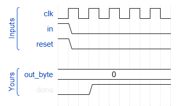
endmoduleps/2 parser and data path
verilog
module top_module(
    input clk,
    input [7:0] in,
    input reset,    // Synchronous reset
    output [23:0] out_bytes,
    output done); //
	parameter B1=2'd0, B2=2'd1, B3=2'd2, D=2'd3;
    // State transition logic (combinational)
    reg[1:0] state, next_state;
    always @(*) begin
        case(state)
            B1: next_state = in[3]? B2:B1;
            B2: next_state = B3;
            B3: next_state = D;
            D: next_state = in[3]? B2:B1;
        endcase
    end
    // State flip-flops (sequential)
    always @(posedge clk) begin
        if(reset) state <= B1;
        else begin
            state <= next_state;
            case(state)
                B1: out_bytes[23:16] <= in;
                B2: out_bytes[15:8] <= in;
                B3: out_bytes[7:0] <= in;
                D: out_bytes[23:16] <= in;
            endcase
        end
    end
    // Output logic
    assign done = (state==D);
    // New: Datapath to store incoming bytes.

endmodule
serial receiver
- 花了比较久时间在如何判断
done
verilog
module top_module(
    input clk,
    input in,
    input reset,    // Synchronous reset
    output done
);
	parameter WAIT=2'd0, BYTE=2'd1, STOP=2'd3, W=4'd8;
    reg[1:0] state, next_state;
    reg[3:0] counter;
    wire b8;
    assign b8 = (counter>=W)? 1'b1: 1'b0;
    always @(*) begin
        case(state)
            WAIT: next_state = ~in? BYTE: WAIT;
            BYTE: next_state = b8? STOP: BYTE;
            STOP: next_state = in? WAIT:STOP;
            default: next_state = 'x;
        endcase
    end
    always @(posedge clk) begin
        if(reset) begin
            counter <= '0;
            state <= WAIT;
        end
        else begin
            state <= next_state;
            counter <= (next_state==BYTE | next_state==STOP)? counter+1'b1: '0; //next_state==BYTE其实代表这个周期就是BYTE状态,因为上一句赋值了
        end
        done <= (next_state==WAIT)&(state==STOP) & (counter==5'd9);
    end
    // done的时序比stop慢一拍,所以直接assign不符合时序要求
    // assign done = (next_state==WAIT)&(state==STOP);
endmodule- 看到了网上引入
ERROR状态,这样可以简化done的判别条件,图片中最后一行显示state[0]的状态,在第二个周期从WAIT状态变为BYTE状态。
verilog
module top_module(
    input clk,
    input in,
    input reset,    // Synchronous reset
    output done
);
	parameter WAIT=2'd0, BYTE=2'd1, ERROR=2'd2, STOP=2'd3, W=4'd8;
    reg[1:0] state, next_state;
    reg[3:0] counter;
    wire b8;
    assign b8 = (counter>=W)? 1'b1: 1'b0;
    always @(*) begin
        case(state)
            WAIT: next_state = ~in? BYTE: WAIT;
            BYTE: next_state = b8? (in? STOP: ERROR): BYTE;
            STOP: next_state = ~in? BYTE: WAIT;
            ERROR: next_state = in? WAIT: ERROR;
        endcase
    end
    always @(posedge clk) begin
        if(reset) begin
            counter <= '0;
            state <= WAIT;
        end
        else begin
            state <= next_state;
            counter <= (state==BYTE)? counter+1'b1: '0; //使用state==BYTE,counter=8时的时间延迟了
        end

        // 如果不引入ERROR状态,直接通过下面式子也可判断done
        // done <= (next_state==WAIT)&(state==STOP) & (counter==5'd9);
    end
    assign done = state==STOP;
    // done的时序比stop慢一拍,所以直接assign不符合时序要求
    // assign done = (next_state==WAIT)&(state==STOP);
endmodule
serial receiver and data path
- 在上一题带有
ERROR状态的always时序逻辑块里赋值,网上有解答用移位赋值,下一道题我用了移位赋值
verilog
if (next_state==BYTE) out_byte[counter] <= in;Serial receiver with parity check
verilog
module top_module(
    input clk,
    input in,
    input reset,    // Synchronous reset
    output [7:0] out_byte,
    output done
); //

    // Modify FSM and datapath from Fsm_serialdata
	parameter WAIT=3'd0, BYTE=3'd1, ERROR=3'd2, STOP=3'd3, PARITY=3'd4, W=4'd8;
    reg[2:0] state, next_state;
    reg[3:0] counter;
    reg p_check; // 检查结果需要留到下一个周期
    wire b8, odd, parity_reset;
    // 组合逻辑连线
    parity p(clk, parity_reset, in, odd);
    assign b8 = (counter>=W)? 1'b1: 1'b0;
    assign parity_reset = (state==WAIT | state==STOP); // 从start开始,因为要触发reset,start是0,不会影响。
    always @(*) begin
        case(state)
            WAIT: next_state = ~in? BYTE: WAIT;
            BYTE: next_state = b8? PARITY: BYTE;
            PARITY: next_state = in? STOP: ERROR; // 不能用  (p_check &in) 这样在in正常是stop位,但是parity错,会误入ERROR状态。
            STOP: next_state = ~in? BYTE: WAIT;
            ERROR: next_state = in? WAIT: ERROR;
        endcase
    end
    always @(posedge clk) begin
        if(reset) begin
            counter <= '0;
            state <= WAIT;
            p_check <= '0;
        end
        else begin
            state <= next_state;
            counter <= (state==BYTE)? counter+1'b1: '0; //使用state==BYTE,counter=8时的时间延迟了
        end
    // New: Datapath to latch input bits.
        case(next_state)
        	BYTE: begin
                out_byte <= {in, out_byte[7:1]};
            end
        endcase
        if(state==PARITY) p_check <= odd;

    end
    assign done = p_check &(state==STOP);
    // New: Add parity checking.

endmodule
Q8: Design a Mealy FSM
- 注意时序逻辑块的敏感列表上升沿和下降沿使用
verilog
module top_module (
    input clk,
    input aresetn,    // Asynchronous active-low reset
    input x,
    output z );
	parameter S0=2'd0, S1=2'd1, S10=2'd2;
    reg[1:0] state, next_state;
    always @(*) begin
        case(state)
            S0: next_state = x? S1: S0;
            S1: next_state = x? S1: S10;
            S10: next_state = x? S1: S0;
            default: next_state = 'x;
        endcase
    end
    always @(posedge clk, negedge aresetn) begin
        if(~aresetn) state <= S0;
        else state <= next_state;
    end
    assign z = x & (state==S10);
endmodule
q5a: serial two's complement (moore FSM)
- 状态里存储{进位,当前位}
verilog
module top_module (
    input clk,
    input areset,
    input x,
    output z
);
    // 状态里存储{进位,当前位}
    // S2代表有进位,当前位0,S0,S1代表无进位当前为0和1,S3没用,不可能到达的状态
    parameter S0= 2'd0, S1=2'd1, S2=2'd2, S3=2'd3;
    reg[1:0] state, next_state;
    always @(*) begin
        case(state)
            S0: next_state = ~x? S1:S0;
            S1: next_state = ~x? S1:S0;
            S2: next_state = ~x? S2: S1;
            default: next_state = 'x;
        endcase
    end
    always @(posedge clk, posedge areset) begin
        if(areset) state<=S2;
        else state<=next_state;
    end
    assign z = state[0];
endmodule
q5a: serial two's complement (Mealy FSM)
- 只使用进位作为状态
verilog
module top_module (
    input clk,
    input areset,
    input x,
    output z
);
    // 相当于是加法器的cout,即进位
	parameter A=1'b1, B=1'b0;
    reg state, next_state;
    always @(*) begin
        case(state)
        	A: next_state = x? B: A;
            B: next_state = B;
        endcase
    end
    always @(posedge clk, posedge areset) begin
        if(areset) state <= A;
        else state <= next_state;
    end
    assign z = x? state: (~state);
endmodule
q3a: FSM
- 被折磨了2h
verilog
module top_module (
    input clk,
    input reset,   // Synchronous reset
    input s,
    input w,
    output z
);
    // 计数不再合并到状态里,单独计数
	parameter A=2'd0, B=2'd1, B2=2'd2, B3=2'd3;
    reg[1:0] state, next_state, count;
    reg w_s;
    always @(*) begin
        case(state)
            A: next_state = s? B: A;
            B: next_state = B2;
            B2: next_state = B3;
            B3: next_state = B;
        endcase
    end
    always @(posedge clk) begin
        if(reset) begin
            state<=A;
            count <= '0;
        end
        else begin
            state <= next_state;
            w_s <= w;
            if(next_state>A)
                count <= (state==B)? (w? 2'd1:2'd0): (w? count + 2'd1: count);// 尝试用next_state==B判断,会提前一个相位。
            // z <= (state==B) & (count==2'd2);
        end
    end
    // assign z = (state==B)& w;
    assign z = (state==B) & (count==2'd2);
endmodule
Q6 FSM (Q2a FSM)
- Q6 FSM 和1Q2a FSM只有w取反的区别,下面列出Q6的代码
verilog
module top_module (
    input clk,
    input reset,     // synchronous reset
    input w,
    output z);
	parameter A=3'd0, B=3'd1, C=3'd2, D=3'd3, E=3'd4, F=3'd5;
    reg[2:0] state, next_state;
    always @(*) begin
        case(state)
            A: next_state = w? A: B;
            B: next_state = w? D: C;
            C: next_state = w? D: E;
            D: next_state = w? A: F;
            E: next_state = w? D: E;
            F: next_state = w? D: C;
        endcase
    end
    always @(posedge clk) begin
        if(reset) state <= A;
        else state <= next_state;
    end
    assign z = (state==E) | (state==F);
endmodule
Q2b Another FSM
- 测例给的周期表明101序列上升沿后立即要输出f=1,而不是等一个周期后输入。
verilog
module top_module (
    input clk,
    input resetn,    // active-low synchronous reset
    input x,
    input y,
    output f,
    output g
);
	parameter A=3'd0, F_S=3'd1, X_MON=3'd2, Y_MON=3'd3, Y_MON_1=3'd4, SUC=3'd5, FAIL=3'd6;
    reg[2:0] state, next_state, rec;
    wire enter_g;
    // 组合逻辑连线
    assign enter_g = (rec[0] & ~rec[1] & rec[2]);
    always @(*) begin
        case(state)
            A: next_state = F_S;
            F_S: next_state = X_MON;
            X_MON: next_state = enter_g? Y_MON: X_MON;
            Y_MON: next_state = y? SUC:FAIL;
            // Y_MON: next_state = y? SUC:Y_MON_1;
            // Y_MON_1: next_state = y? SUC:FAIL;
            SUC: next_state = SUC;
            FAIL: next_state = FAIL;
            default: next_state = 'x;
        endcase
    end
    always @(posedge clk) begin
        if(~resetn) begin
            state <= A;
            rec <= 0;
        end
        else begin
            state <= next_state;
            if(state==X_MON) rec <= {rec[1:0], x};
        end
    end
    assign f = state==F_S;
    // (next_state==Y_MON)为了提前f的输出周期,实际上使用的测例是在101序列中1出现的上升沿后立即产生f=1
    assign g = (next_state==Y_MON) | (state==Y_MON) | (state==SUC);
endmodule